CN2359730Y - Speaker mounts for computer monitors - Google Patents
Speaker mounts for computer monitors Download PDFInfo
- Publication number
- CN2359730Y CN2359730Y CN 98240225 CN98240225U CN2359730Y CN 2359730 Y CN2359730 Y CN 2359730Y CN 98240225 CN98240225 CN 98240225 CN 98240225 U CN98240225 U CN 98240225U CN 2359730 Y CN2359730 Y CN 2359730Y
- Authority
- CN
- China
- Prior art keywords
- several
- audio amplifier
- display housing
- breach
- computer monitor
- Prior art date
- Legal status (The legal status is an assumption and is not a legal conclusion. Google has not performed a legal analysis and makes no representation as to the accuracy of the status listed.)
- Expired - Fee Related
Links
- 238000009434 installation Methods 0.000 claims 4
- 238000007373 indentation Methods 0.000 claims 1
- 238000000034 method Methods 0.000 description 2
- 239000012141 concentrate Substances 0.000 description 1
- 238000010586 diagram Methods 0.000 description 1
- 239000012636 effector Substances 0.000 description 1
Images
Landscapes
- Details Of Audible-Bandwidth Transducers (AREA)
Abstract
Description
本实用新型涉及一种电脑显示器的音箱固定装置。The utility model relates to a sound box fixing device of a computer monitor.
一般常见的电脑显示器的音箱固定装置具有一显示器壳体,并在该显示器壳体内藉一框架上所设的固定座将音箱框设在框架上,其后,再藉锁固元件(如螺丝),令该框架可与该显示器壳体接设在一起,或者直接将该音箱置放在显示器壳体的周边位置处,但此种音箱固定方式非常不方便,同时,当使用中的音效器发出较大音效时,此种利用锁固元件令音箱锁固在显示壳体内的锁固方式,将会令整部电脑显示器所产生的震动效果集中在锁固元件上,形成日后锁固元件的松动,进而造成对该显示器壳体内机件的伤害。Generally, the speaker fixing device of a common computer monitor has a display casing, and the speaker frame is arranged on the frame by a fixed seat provided on the frame in the display casing, and then the locking element (such as a screw) is used to fix the speaker frame. , so that the frame can be connected with the display casing, or the speaker can be placed directly on the periphery of the display casing, but this kind of speaker fixing method is very inconvenient. When the sound effect is large, this kind of locking method using the locking element to lock the speaker in the display case will concentrate the vibration effect generated by the entire computer monitor on the locking element, resulting in loosening of the locking element in the future , And then cause damage to the internal parts of the display housing.
本实用新型的目的在于提供一种电脑显示器的音箱固定装置,可使音箱内音效器所发出的重低音、全音域效果更为加强,且更加轻易及稳固地将音箱嵌设在显示器壳体中。The purpose of this utility model is to provide a speaker fixing device for a computer monitor, which can strengthen the subwoofer and full-range effects emitted by the sound effect device in the speaker, and embed the speaker in the display casing more easily and firmly. .
本实用新型的目的是这样实现的,即提供一种电脑显示器的音箱固定装置,它包括:一显示器壳体,其在远离显示幕后方的任一侧设有至少一缺口,所述缺口的内缘设有一与其相对配合的板体,所述板体于适当位置处分别设有一贯穿孔及数个嵌接元件;一音箱,其在对应于所述显示器壳体的板体的贯穿孔及数个嵌接元件位置处适当地设有一中空管体及数个另一嵌接元件,所述数个另一嵌接元件嵌扣在所述板体的数个嵌接元件内,同时所述中空管体穿套于所述贯穿孔内,所述音箱与显示器壳体的缺口结合为一体。The purpose of this utility model is achieved by providing a speaker fixing device for a computer monitor, which includes: a display housing, which is provided with at least one notch on any side away from the rear of the display screen, and the inner part of the notch is The edge is provided with a board corresponding to it, and the board is respectively provided with a through hole and several embedding elements at appropriate positions; A hollow pipe body and several other embedding elements are appropriately provided at the positions of the embedding elements, and the several other embedding elements are embedded and buckled in the several embedding elements of the plate body, while the The hollow tube is sheathed in the through hole, and the sound box is integrated with the notch of the display housing.
本实用新型装置的优点在于,音箱能藉由板体不占空间的设置,更加轻易及稳固地将音箱嵌设在显示器壳体中,同时音箱所发出的声音效果将更为加强。The advantage of the device of the utility model is that the sound box can be embedded in the display casing more easily and stably by the arrangement of the board body without occupying space, and the sound effect emitted by the sound box will be more enhanced.
以下结合附图,描述本实用新型的实施例,其中:Below in conjunction with accompanying drawing, describe embodiment of the present utility model, wherein:
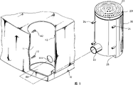
图1为本实用新型的立体分解图;Fig. 1 is the three-dimensional exploded view of the utility model;
图2为本实用新型的嵌扣示意图。Fig. 2 is a schematic diagram of the embedded buckle of the present invention.
请参阅图1、2所示,本实用新型电脑显示器的音箱固定装置具有一电脑显示器壳体10,其任一侧配合外形设有一缺口101,于本实施例中,该缺口101呈弧状,且位于显示器壳体10远离显示幕后方的任一侧,该弧状缺口101亦可设在远离显示幕后方的左、右两侧,该弧状缺口101的内缘设有一相对配合其内缘的弧状板体11,并于该弧状板体11的适当位置处分别设有一贯穿孔111及数个嵌接元件112。Please refer to Fig. 1, shown in 2, the speaker fixing device of the computer monitor of the present invention has a
本实用新型中,该显示器壳体10的弧状缺口101位置处恰可嵌设一音箱20,于本实施例中,该音箱20呈圆筒状,以作为重低音、全音域喇叭音箱之用,并于该音箱20的一端内嵌设有一音效器(图中未示),该音效器上并设有一可与音箱20结合为一体的盖体22,该盖体22上设有数个孔洞221,可藉由这些孔洞221令声音顺利地发出。In the present utility model, a
本实用新型中,该音箱20于对应弧状板体11的贯穿孔111及数个嵌接元件112位置处适当地凸设有一中空管体23及数个另一嵌接元件24(如图所示),这些另一嵌接元件24可对应嵌扣在弧状板体11的数个嵌接元件112内,同时该中空管体23恰可穿套于贯穿孔111内(如图2所示),且可藉由该中空管体23加强该音箱20的重低音、全音域效能,该音箱20于音效器的另一端且对应该显示器壳体10的弧状缺口101底缘处形成有一缺槽25(如图1所示),使该音箱20容置于该弧状缺口101处时,该缺槽25恰可与显示器壳体10的弧状缺口101密合,同时该音箱20与显示器壳体10的弧状缺口101将结合为一体。In the present utility model, the
请参阅图1、2所示,本实用新型在实施时,将音箱20上的中空管体23及数个另一嵌接元件24嵌插在弧状板体11的贯穿孔111及数个嵌接元件112内,并可分别藉螺丝30将其锁固于已嵌接后的数个嵌接元件112及数个另一嵌接元件24上(如图2所示),以达更加稳固之效,同时,该音箱20另一端的缺槽25则恰好抵靠在弧状缺口101的底缘处,进而令该音箱20与显示器壳体10的弧状缺口101结合为一体,其不仅充分地利用该显示器壳体10的空间,同时通过该弧状板体11不占空间的设置,将令该音箱20内音效器所发出的重低音、全音域效果更为加强,且更加轻易及稳固地将音箱20嵌设在显示器壳体10中。Please refer to Figs. 1 and 2, when the utility model is implemented, the
Claims (4)
Priority Applications (1)
| Application Number | Priority Date | Filing Date | Title |
|---|---|---|---|
| CN 98240225 CN2359730Y (en) | 1998-09-22 | 1998-09-22 | Speaker mounts for computer monitors |
Applications Claiming Priority (1)
| Application Number | Priority Date | Filing Date | Title |
|---|---|---|---|
| CN 98240225 CN2359730Y (en) | 1998-09-22 | 1998-09-22 | Speaker mounts for computer monitors |
Publications (1)
| Publication Number | Publication Date |
|---|---|
| CN2359730Y true CN2359730Y (en) | 2000-01-19 |
Family
ID=33987311
Family Applications (1)
| Application Number | Title | Priority Date | Filing Date |
|---|---|---|---|
| CN 98240225 Expired - Fee Related CN2359730Y (en) | 1998-09-22 | 1998-09-22 | Speaker mounts for computer monitors |
Country Status (1)
| Country | Link |
|---|---|
| CN (1) | CN2359730Y (en) |
-
1998
- 1998-09-22 CN CN 98240225 patent/CN2359730Y/en not_active Expired - Fee Related
Similar Documents
| Publication | Publication Date | Title |
|---|---|---|
| US20140139998A1 (en) | Server rack | |
| JP2009194541A (en) | Thin type television of thin structure | |
| JP4937707B2 (en) | Electronic device including a metal housing and a decorative envelope | |
| CN2359730Y (en) | Speaker mounts for computer monitors | |
| TWM507142U (en) | Computer accessory fastening rack structure and computer case thereof | |
| JP2005197421A (en) | Electronic apparatus | |
| US20060238725A1 (en) | Projection apparatus provided with a modular device | |
| CN101202124A (en) | Installation fixing device of parallel heat dissipation component | |
| CN2321182Y (en) | Computer monitor speaker mount with notch embedding | |
| JPH1061974A (en) | Air conditioner | |
| JP3503975B2 (en) | Power unit mounting structure | |
| CN219437342U (en) | Heat dissipation shell for installing LED film screen | |
| CN2330124Y (en) | Computer monitor speaker fixing seat embedded in the inner side | |
| JPH075655Y2 (en) | Body structure of communication equipment | |
| JPS6318229Y2 (en) | ||
| JP2009010790A (en) | Doorphone slave device | |
| JP4059096B2 (en) | Plasma display device | |
| TWI293358B (en) | Lamp with a player device | |
| JP3204069B2 (en) | Panel instrument mounting device | |
| US20020146331A1 (en) | UPS in combination with a fan | |
| JP2004088224A (en) | Bass reflex type speaker | |
| CN202243246U (en) | Combined structure of driving recorder | |
| JP3661025B2 (en) | Enclosure sealing structure | |
| TWM347009U (en) | Casing of screwless for fixing circuit board | |
| JPH0951176A (en) | Box for storing electric equipment |
Legal Events
| Date | Code | Title | Description |
|---|---|---|---|
| C14 | Grant of patent or utility model | ||
| GR01 | Patent grant | ||
| C19 | Lapse of patent right due to non-payment of the annual fee | ||
| CF01 | Termination of patent right due to non-payment of annual fee |