CN2239438Y - D.C magnetic control sputter power source - Google Patents
D.C magnetic control sputter power source Download PDFInfo
- Publication number
- CN2239438Y CN2239438Y CN 96206867 CN96206867U CN2239438Y CN 2239438 Y CN2239438 Y CN 2239438Y CN 96206867 CN96206867 CN 96206867 CN 96206867 U CN96206867 U CN 96206867U CN 2239438 Y CN2239438 Y CN 2239438Y
- Authority
- CN
- China
- Prior art keywords
- circuit
- power supply
- phase
- sputtering power
- controlled
- Prior art date
- Legal status (The legal status is an assumption and is not a legal conclusion. Google has not performed a legal analysis and makes no representation as to the accuracy of the status listed.)
- Expired - Fee Related
Links
Images


Landscapes
- Rectifiers (AREA)
Abstract
The utility model provides a D. C magnetic control sputter power source. The utility model is provided with a three-phase AC power supply input circuit, a three-phase controllable bridge rectifier circuit whose AC input end is connected with the three-phase AC power supply input circuit, an adjustment control circuit whose input end is connected with the three-phase controllable bridge rectifier circuit, and a thyristor trigger control circuit which is connected with the adjustment control circuit. When the arcing is carried out, the arc interruption can be realized quickly, and the utility model can automatically recover to the normal operating condition, which can reliably protect the sputtering target and the circuit. When the sputtering of various film systems is carried out, the optimal sputtering operating mode can be selected according to different technological requirements. The utility model has the advantages of stable operation, high sputtering rate, superior quality, and good repeatability.
Description
The utility model relates to a kind of DC power supply device, particularly be a kind of magnetically controlled DC sputtering power supply that is used for the large glass coating film production line.
The modern architecture coated glass nearly all adopts the method preparation of magnetically controlled DC sputtering (companion's reaction magnetocontrol sputtering).Because transparency area is big, must load onto large-scale magnetic controlling target and carry out continuous sputter plating with large continuous glass coating machine.The power of the used direct supply of large-scale magnetron sputtering target increases along with the increase of area.Present domestic 2000 * 1600m
2(even 2000 * 3300mm
2) the power of the used magnetron sputtering target of glass all below 50KW.Because power is less than normal, production efficiency is low, and makes difficulty of various films system, simultaneously since during sputter the sparking arcing inevitable, along with the increase of power, also important all the more to the resist technology of sparking arcing, difficulty is also increasing.The sparking arcing causes burning out insurance, rectifying component and magnetron sputtering target often; The mode of operation that requires power supply to adopt during sputter also only limits to a kind of current mode, a retaining voltage, the processing requirement of the various films of the sputter system that the load variations in the time of can not satisfying actual sputter requires.
In view of above reason, the purpose of this utility model is can increase output power of power supply in order to provide a kind of, and the sputtering technology that satisfies large high-speed sputter magnetic controlling target requires the magnetically controlled DC sputtering power supply of needs.
The three-phase alternating-current supply input circuit is arranged in the utility model, the controlled bridge rectifier circuit of three-phase that ac input end is connected with the three-phase alternating-current supply input circuit, the adjusting pilot circuit that input terminus is connected with the controlled bridge rectifier circuit of three-phase, with the silicon controlled rectifier trigger control circuit (referring to Fig. 1, Fig. 5) that the adjusting pilot circuit is connected, optional with electric current, voltage, three kinds of mode of operation of power and three kinds of different operating voltage.
Be serially connected with telefault L in the above-mentioned magnetically controlled DC sputtering power output circuit, regulating in the pilot circuit has current threshold N
16B, voltage threshold N
16A, voltage threshold N
16A, current threshold N
16Receive triode V after the B parallel connection
2Base stage and signal can be delivered to triode V
1, in regulating pilot circuit, also be provided with and triode V
1The transport and placing device N that collector electrode connects
9, soft starting circuit V
1, R
26, C
8Be connected to transport and placing device N
9Input terminus, realize the soft start (referring to Fig. 1, Fig. 3) behind the arcing, N
16A, N
16It is the comparer of LM339 that B can adopt model, V
2Can adopt the 2N3703 type, N
9Can adopt OP07 type transport and placing device, change resistance R
26Or capacitor C
8Can change the speed of soft start, telefault L and N
16A, N
16B, V
2, V
1Form sparking arcing holding circuit, made sputtering target working properly, safe, reliable, and had auto restore facility behind the arcing.
Input terminus in the above-mentioned adjusting pilot circuit has the operational amplifier of isolation N
1, N
2(referring to Fig. 3), N
1, N
2Can adopt AD289 type operational amplifier, can make and regulate the control unit works better.
In the above-mentioned adjusting pilot circuit analog multiplier N is arranged
3(referring to Fig. 3) participates in circuit conditioning operation, N with the realtime power value after voltage and current multiplied each other
3Can adopt model is AD35 pattern quasi-multiplication device.
Differential (D) circuit N is arranged in the above-mentioned adjusting pilot circuit
9, integration (I) circuit N
12, ratio regulates (P) circuit N
11(referring to Fig. 3), N
9, N
12, N
11Adopt OP07 type transport and placing device, make circuit have the P.I.D regulatory function, make work more steadily, reliably.
Six silicon controlled rectifier V are arranged in the controlled bridge rectifier circuit of above-mentioned three-phase
1~V
0And attached electronic element R
1~R
12, C
1~C
12(referring to Fig. 6) forms an air-cooled one-piece construction, little, the compact construction of volume.
The alternating current contactor K that is loaded on the three-phase transformer is arranged in the above-mentioned three-phase alternating-current supply input circuit
2, K
3, K
4, regulating in the pilot circuit has and alternating current contactor K
2, K
3, K
4The photoelectrical coupler N that is communicated with
18~N
24When (referring to Fig. 2, Fig. 3, Fig. 6), voltage gear select signal to provide, make alternating current contactor K on the one hand
2, K
3, K
4In some work, the related circuit of regulating in the pilot circuit is connected, by photoelectrical coupler N
18~N
24Finish circuit conversion; In like manner, when the signal of mode of operation provided, the related circuit of regulating in the pilot circuit was connected, and finishes circuit conversion by photoelectrical coupler, photoelectrical coupler N
18-N
24Can adopt the H11F1 type.
In the above-mentioned silicon controlled rectifier trigger control circuit triode of containing V is arranged
3, V
7, V
11, double-base diode V
5, V
9, V
13, capacitor C
16, C
17, C
18Sawtooth-wave generator (referring to Fig. 4).
The utility model power supply can independently be powered to magnetron sputtering target; exportable three kinds of different voltages; by changing the mode of the secondary tap of three-phase transformer; realize each retaining conversion; the maximum current of each retaining output can be 160A; 123A; 100A; output rating all can be 80KW; and the fine tuning of voltage can be realized by circuit for regulating and controlling; its operation scheme can be an electric current; voltage or power mode; power is big; circuit has the unique arcing of sparking reliably holding circuit; current interruption rapidly promptly automatically restores to normal operating condition subsequently very soon during arcing, and sputtering target and circuit are had the reliable protection effect.Also have the P.I.D regulatory function in the circuit, make when the various films of sputter are, can select best sputter running status, sputter, coating process working stability, sputtering raste height, institute's plated film superior in quality, good reproducibility according to the different process requirement.This power supply can be widely used in magnetron sputtering glass coating production line, and its control methods, the protection of sparking arcing also can be widely used in the circuit for regulating and controlling of similar sputtering equipment and other power supplys.
Describe embodiment of the present utility model in detail below in conjunction with accompanying drawing:
Fig. 1 is the utility model block diagram.
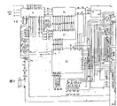
Fig. 2 is the utility model power sourced electric schematic diagram.
Fig. 3 is for regulating the pilot circuit electrical schematic diagram.
Fig. 4 is a silicon controlled rectifier trigger control circuit electrical schematic diagram.
Fig. 5 divides electrical schematic diagram for power input part.
Fig. 6 is the controlled bridge rectifier circuit electrical schematic diagram of three-phase.
Referring to Fig. 1~Fig. 6, AC power input circuit 1 is arranged, in the utility model by six silicon controlled rectifier V
1~V
6And attached electronic element R
1~R
12, C
1~C
12Deng the controlled bridge rectifier circuit of forming 2 of three-phase, adjusting pilot circuit 3, silicon controlled rectifier trigger control circuit 4, control panel 5.
It is elementary that three-phase supply is connected to three-phase transformer through the master control contactor, transformer secondary output is connected to the ac input end of three-phase controlled (full control) bridge rectifier through contactor, fuse cutout, after the rectification, negative terminal is received on the magnetron sputtering target behind telefault L, and its anode is received anode behind sampling resistor.From sampling resistor R
0On the current feedback signal obtained and the voltage signal of drawing from the output negative terminal be added to (X Fig. 3 on respective input of regulating pilot circuit
21,7,8,10 terminals), because these two signals from the forceful electric power high-pressure side, are the low pressure weak current parts and regulate pilot circuit, if do not take effective high-low pressure quarantine measures, might make regulate pilot circuit can't works better, and may damage its components and parts.So adopt high voltage bearing isolation transport and placing device (N
1, N
2When model AD289) regulating control with voltage and power mode work after the amplification again, circuit also has the P.I.D regulatory function, makes work more steady, authentic simulation multiplier N
3Voltage and current is multiplied each other the back with realtime power value product and circuit conditioning operation.
Deliver to the input amplifier N of triggering circuit from the main inspection signal of regulating pilot circuit output
1(referring to Fig. 4), also have one the tunnel to be added to the same end of input amplifier simultaneously through isolating amplified current feedback signal (taking from RP18 among Fig. 3), so that operation with closed ring is more stable, these two signals are after addition is amplified, and output is gone to regulate and contained triode V in the thyristor gating circuit
3, V
4, V
7Double-base diode V
5, V
9, V
13, capacitor C
16, C
17, C
18The frequency of sawtooth-wave generator changing the silicon controlled conduction angle, is regulated and the purpose of regulated output voltage thereby reach.
Sputter is in service; the sparking arcing can't be avoided fully; and the consequence of sparking arcing is very serious, may cause burning out target, burn out the circuit elements device, causes the general supply tripping operation; thereby make full workshop or power cut of whole factory; the serious normal operation of disturbing other electrical appliances or equipment, therefore, the utility model adopts unique sparking arcing holding circuit defencive function perfect; reliably, and have a function of the normal operation of automatic recovery.This circuit is provided with current threshold control, i.e. comparer (LM339) N among Fig. 3 to sparking or the arcing that has caused
16B, and the too high voltages that faces the danger of sparking arcing to not striking sparks arcing as yet is provided with the voltage valve, i.e. N among Fig. 3
16A, the generation of the arcing that so both can prevent to strike sparks, not only can to but also the sparking arcing that takes place limited, it is led to grave consequences.As can be seen from Figure 3, N
16A, N
16There is one tunnel output can make V among the B
2Conducting, V
2One conducting will have two signals to send, because receive triode V after two comparator output terminal parallel connections
2Base stage (2N3703) is so one the tunnel make triode V
1Conducting reduces to zero rapidly with input signal, and it is bright to hinder arc lamp simultaneously, and the V of trigger control circuit is delivered on another road
1Transistor base; make its conducting; input conditioning signal short circuit with sawtooth-wave generator; because silicon controlled rectifier loses and touches threshold signal; so stop output voltage immediately; arcing is disappeared immediately; thereby protected target and circuit elements device not reason sharp increase after-current damage; owing to be in series with inductance L in the power output circuit; the speed of current increases is restricted when making arcing, and the arcing holding circuit is really worked, so inductance L also is an indispensable element in the sparking arcing holding circuit; this is one of effect of sparking arcing holding circuit; sparking arcing one disappears, the circuit state of should resuming work immediately, and this is second effect that holding circuit should be finished; because the big electric current during arcing (or not causing the too high voltages that arcing is preceding) has not existed through above-mentioned " resistance arc " process, so N
16A or N
16B, V
2, V
1All recover standard state, N
9Transport and placing device (OP07) input signal through soft starting circuit R
26, C
8Return to original value very soon, entire circuit also just returns to original working order, this automatic restoring circuit is very concise and to the point, reliably, as can be seen, the selection of three voltage 500V, 650V, 800V and three kinds of work is by the control signal control of other control sections such as the button of control panel or PLC, as long as signal one arrives from Fig. 3 circuit, circuit just automatically the input selected voltage of the control signal of giving and mode of operation work, be independent of each other.
Six silicon controlled rectifiers of the controlled bridge rectifier circuit of three-phase and protective element thereof, form an air-cooled one-piece construction, volume is little, compact construction, silicon controlled rectifier clamping are between the copper billet of 100mm at flange-cooled, thickness, copper billet is of a size of 100mm * 100mm * 10mm, be welded with the radiating copper sheet of 10 100mm * 40mm * 2mm on every, the side of copper billet is fastened on the hard rubber sheet, the outside covers clamping with cylindrical cover again silicon controlled copper billet one side is arranged, the aerofoil fan of the φ 200mm cooling silicon controlled rectifier of drying from bottom to top.
Dry-type three-phase transformer among Fig. 5 T1 time level is every 233V, 300V, three taps of 367V mutually, and physical dimension is 740mm * 420mm * 650mm.
There are 500V, 650V, three kinds of different operating voltage of 800V and electric current, voltage, three kinds of mode of operation of power independently to power in the present embodiment for selecting for use to magnetron sputtering target.
All components and parts all are contained in the electric cabinet of control in the present embodiment, and the cabinet top is provided with the cooling of two φ, 200 aerofoil fan exhausting, and controlling has action button and pilot lamp etc. on the electric cabinet panel, and its physical dimension is: 1250 * 900 * 1850mm
3
Claims (8)
1, magnetically controlled DC sputtering power supply, it is characterized in that in the described magnetically controlled DC sputtering power supply three-phase alternating-current supply input circuit being arranged, the controlled bridge rectifier circuit of three-phase that ac input end is connected with the three-phase alternating-current supply input circuit, the adjusting pilot circuit that input terminus is connected with the controlled bridge rectifier circuit of three-phase, the silicon controlled rectifier trigger control circuit that is connected with the adjusting pilot circuit.
2, magnetically controlled DC sputtering power supply as claimed in claim 1 is characterized in that being in series with telefault L in the described magnetically controlled DC sputtering power output circuit, and regulating in the pilot circuit has current threshold N
16B, voltage threshold N
16A, voltage threshold N
16A, current threshold N
16Receive triode V after the B parallel connection
2Base stage, and signal can be delivered to triode V
1, in regulating pilot circuit, also be provided with and triode V
1The transport and placing device N that collector electrode connects
9, soft starting circuit V
1, R
26, C
8Be connected to transport and placing device N
9Input terminus.
3, magnetically controlled DC sputtering power supply as claimed in claim 1 is characterized in that the input terminus in the described adjusting pilot circuit has the operational amplifier of isolation N
1, N
2
4, magnetically controlled DC sputtering power supply as claimed in claim 1 is characterized in that in the described adjusting pilot circuit analog multiplier N being arranged
3
5, magnetically controlled DC sputtering power supply as claimed in claim 1 is characterized in that having in the described adjusting pilot circuit differential (D) circuit N
9, integration (I) circuit N
12, ratio regulates (P) circuit N
11
6, magnetically controlled DC sputtering power supply as claimed in claim 1 is characterized in that the alternating current contactor K that is loaded on the three-phase transformer is arranged in the described three-phase alternating-current supply input circuit
2, K
3, K
4, regulating in the pilot circuit has and alternating current contactor K
2, K
3, K
4The photoelectrical coupler N that is communicated with
18~N
24
7, magnetically controlled DC sputtering power supply as claimed in claim 1 is characterized in that six silicon controlled rectifier V are arranged in the controlled bridge rectifier circuit of described three-phase
1~V
6And attached electronic element R
1~R
12, C
1~C
12
8, direct supply shielding power supply as claimed in claim 1 is characterized in that in the described silicon controlled rectifier trigger control circuit triode of containing V being arranged
3, V
7, V
11, double-base diode V
5, V
9, V
13, capacitor C
16, C
17, C
18Sawtooth-wave generator.
Priority Applications (1)
| Application Number | Priority Date | Filing Date | Title |
|---|---|---|---|
| CN 96206867 CN2239438Y (en) | 1996-03-08 | 1996-03-08 | D.C magnetic control sputter power source |
Applications Claiming Priority (1)
| Application Number | Priority Date | Filing Date | Title |
|---|---|---|---|
| CN 96206867 CN2239438Y (en) | 1996-03-08 | 1996-03-08 | D.C magnetic control sputter power source |
Publications (1)
| Publication Number | Publication Date |
|---|---|
| CN2239438Y true CN2239438Y (en) | 1996-11-06 |
Family
ID=33891341
Family Applications (1)
| Application Number | Title | Priority Date | Filing Date |
|---|---|---|---|
| CN 96206867 Expired - Fee Related CN2239438Y (en) | 1996-03-08 | 1996-03-08 | D.C magnetic control sputter power source |
Country Status (1)
| Country | Link |
|---|---|
| CN (1) | CN2239438Y (en) |
Cited By (2)
| Publication number | Priority date | Publication date | Assignee | Title |
|---|---|---|---|---|
| CN104674178A (en) * | 2015-03-24 | 2015-06-03 | 南华大学 | Power circuit for realizing multi-mode outputting of magnetron sputtering coating and control method |
| CN112080728A (en) * | 2020-08-12 | 2020-12-15 | 北京航空航天大学 | HiPIMS system and method for reducing HiPIMS discharge current delay |
-
1996
- 1996-03-08 CN CN 96206867 patent/CN2239438Y/en not_active Expired - Fee Related
Cited By (3)
| Publication number | Priority date | Publication date | Assignee | Title |
|---|---|---|---|---|
| CN104674178A (en) * | 2015-03-24 | 2015-06-03 | 南华大学 | Power circuit for realizing multi-mode outputting of magnetron sputtering coating and control method |
| CN104674178B (en) * | 2015-03-24 | 2017-03-22 | 南华大学 | Power circuit for realizing multi-mode outputting of magnetron sputtering coating and control method |
| CN112080728A (en) * | 2020-08-12 | 2020-12-15 | 北京航空航天大学 | HiPIMS system and method for reducing HiPIMS discharge current delay |
Similar Documents
| Publication | Publication Date | Title |
|---|---|---|
| US8467211B2 (en) | Bipolar pulsed power supply and power supply apparatus having plurality of bipolar pulsed power supplies | |
| US5882492A (en) | A.C. plasma processing system | |
| US6011704A (en) | Auto-ranging power supply | |
| US5889391A (en) | Power supply having combined regulator and pulsing circuits | |
| SU1198132A1 (en) | Installation for chemical and thermal treatment of metal or under glow discharge conditions | |
| CN200956303Y (en) | Non-contact stepless on-load voltage regulating transformer | |
| US20030184926A1 (en) | Hybrid switch module for an AC power capacitor | |
| WO2012023276A1 (en) | Direct current power supply device | |
| WO2006051744A1 (en) | Impedance matching network, and plasma processing apparatus using such impedance matching network | |
| US8734627B2 (en) | Power supply apparatus | |
| US10823157B2 (en) | Frequency control for a frequency generator of an ion engine | |
| CN2239438Y (en) | D.C magnetic control sputter power source | |
| US5990668A (en) | A.C. power supply having combined regulator and pulsing circuits | |
| US5645741A (en) | ARC processing apparatus comprising driving means for controlling output transistor so that output voltage becomes predetermined no-load voltage | |
| US6794618B2 (en) | Method for electrical heating of furnaces for heat treatment of metallic workpieces | |
| US3129357A (en) | Voltage generator for electrolytic erosion processes | |
| CN104538273B (en) | The supply unit of high voltage cold-cathode gas discharge electron gun and control method thereof | |
| CN2189999Y (en) | Plasma-arc and argon arc welding controller with FET d.c.-a.c. converter | |
| US3826889A (en) | System for automatic control of electron beam heating device | |
| CN114043020B (en) | Circuit for removing electric spark machining gap electric erosion product and control method thereof | |
| Bevan | The application of high-voltage steel-tank mercury-arc rectifiers to broadcast transmitters | |
| CN217388219U (en) | DC coating power supply | |
| CN221415322U (en) | Auxiliary superposition arc striking circuit for plasma cutting torch | |
| JP2001275255A (en) | Voltage compensating device | |
| CN210744753U (en) | Switching system of reactive power compensation device |
Legal Events
| Date | Code | Title | Description |
|---|---|---|---|
| C14 | Grant of patent or utility model | ||
| GR01 | Patent grant | ||
| C19 | Lapse of patent right due to non-payment of the annual fee | ||
| CF01 | Termination of patent right due to non-payment of annual fee |