CN2216391Y - Digital remote-controlling micro-cardioelectric monitoring instrument - Google Patents
Digital remote-controlling micro-cardioelectric monitoring instrument Download PDFInfo
- Publication number
- CN2216391Y CN2216391Y CN 95208884 CN95208884U CN2216391Y CN 2216391 Y CN2216391 Y CN 2216391Y CN 95208884 CN95208884 CN 95208884 CN 95208884 U CN95208884 U CN 95208884U CN 2216391 Y CN2216391 Y CN 2216391Y
- Authority
- CN
- China
- Prior art keywords
- circuit
- signal
- amplifier
- electrode
- transmitter
- Prior art date
- Legal status (The legal status is an assumption and is not a legal conclusion. Google has not performed a legal analysis and makes no representation as to the accuracy of the status listed.)
- Expired - Fee Related
Links
- 238000012544 monitoring process Methods 0.000 title abstract description 5
- 238000001914 filtration Methods 0.000 claims abstract description 11
- 238000006243 chemical reaction Methods 0.000 claims abstract description 4
- 238000012360 testing method Methods 0.000 claims abstract description 3
- 238000003199 nucleic acid amplification method Methods 0.000 claims description 12
- 230000003321 amplification Effects 0.000 claims description 11
- 238000007493 shaping process Methods 0.000 claims description 8
- 230000000747 cardiac effect Effects 0.000 claims description 7
- 238000004891 communication Methods 0.000 claims description 6
- 230000002093 peripheral effect Effects 0.000 claims description 2
- 238000010223 real-time analysis Methods 0.000 abstract description 2
- 230000001105 regulatory effect Effects 0.000 abstract description 2
- 238000010586 diagram Methods 0.000 description 10
- 238000012545 processing Methods 0.000 description 5
- 238000005516 engineering process Methods 0.000 description 3
- 238000000034 method Methods 0.000 description 3
- 230000005540 biological transmission Effects 0.000 description 2
- 230000001276 controlling effect Effects 0.000 description 2
- 238000004519 manufacturing process Methods 0.000 description 2
- 230000010355 oscillation Effects 0.000 description 2
- 238000005070 sampling Methods 0.000 description 2
- 230000002159 abnormal effect Effects 0.000 description 1
- 230000005856 abnormality Effects 0.000 description 1
- 238000004458 analytical method Methods 0.000 description 1
- 230000015572 biosynthetic process Effects 0.000 description 1
- 238000007405 data analysis Methods 0.000 description 1
- 238000013461 design Methods 0.000 description 1
- 238000001514 detection method Methods 0.000 description 1
- 238000002405 diagnostic procedure Methods 0.000 description 1
- 238000007599 discharging Methods 0.000 description 1
- 230000000694 effects Effects 0.000 description 1
- 238000005265 energy consumption Methods 0.000 description 1
- 230000036039 immunity Effects 0.000 description 1
- 230000008676 import Effects 0.000 description 1
- 239000004615 ingredient Substances 0.000 description 1
- 238000007689 inspection Methods 0.000 description 1
- 230000007774 longterm Effects 0.000 description 1
- 238000007726 management method Methods 0.000 description 1
- 238000005259 measurement Methods 0.000 description 1
- 238000004321 preservation Methods 0.000 description 1
- 238000011897 real-time detection Methods 0.000 description 1
- 238000011084 recovery Methods 0.000 description 1
Images


Landscapes
- Measurement And Recording Of Electrical Phenomena And Electrical Characteristics Of The Living Body (AREA)
Abstract
The utility model belongs to the technical field of a digital remote-controlling cardioelectric monitoring instrument controlled by a microcomputer. The utility model comprises a portable transmitter composed of an exploring electrode, a pre-amplifier, a filtering wave, a regulating circuit, an A/D converting circuit, a monolithic computer, a frequency modulating transmitting circuit, an electrode calling and testing circuit and a power conversion circuit, and a receiving card circuit composed of a receiving amplifying circuit, a demodulating and demoding circuit, an interface and a control circuit. The utility model has the advantages of strong noninterference, reliable work, low power consumption, compact structure, small size, etc. and can be connected with a PC conveniently to carry out the real-time analysis of cardioelectric data, storage, playback, alarm and display, having an application to monitor patients in hospitals and self care in families.
Description
This utility model belongs to micro-processor controlled digital cardiac telemetry instrument design and manufacturing technology field.
Domestic existing cardiac telemetry monitor device is direct remote measurement with analog quantity basically at present, and its anti-interference is poor, and function is few, and volume is big; The digital ecg telemetry system that some adopt special-purpose monster chip to constitute abroad appears, but because its cost height, the production difficulty can't be widely used in average family greatly and use.
The purpose of this utility model is to overcoming the weak point of prior art, utilize modernized microprocessor control technology, a kind of cardiac telemetry monitor of minitype digital is provided, realization to the electrocardiosignal of user for a long time, regularly, accurate remote control detection and diagnostic process, and have multiple functional, the reliability height, characteristics such as cost is low, and volume is little.
Minitype digital cardiac telemetry monitor described in the utility model is made up of backpack transmitter and remote control receiving card two parts, and it is characterized in that: said transmitter comprises the exploring electrode of surveying electrocardiosignal; The electrocardiosignal preamplifier that detectable signal is amplified; Filtering and level adjusting circuit that the electrocardiosignal of amplifying is carried out filtering and adjustment; Adjusted analog signal conversion is become the A/D change-over circuit of digital signal; Single-chip microcomputer and peripheral circuit thereof that digital signal is handled and each circuit is controlled; Signal after handling through the single-chip microcomputer coding is carried out frequency give synthetic frequency shift keying (FSK) primary modulation circuit, the modulating emission circuit that again its signal is carried out frequency modulation for the second time and launch with high frequency carrier, and provide the power converting circuit of different voltages and to the electrode that said electrode signal the detects testing circuit that comes off for each circuit; Said receiving card comprises the reception amplifying circuit that the signal to transmitter emission receives and amplifies, this signal is demodulated to the FSK demodulator circuit of digital signal, its signal is amplified the amplification and rectification circuit of shaping, again to the signal after the shaping decode the decoding circuit that obtains electrocardiogram (ECG) data and with interface and the control circuit of these data being sent into the PC bus.
Pre-amplification circuit in the said transmitter of this utility model can constitute three amplifier differential amplifiers by the low-power consumption amplifier; Said filtering and shaping circuit can comprise the filter circuit that is made of double T trap active circuit, the block isolating circuit that is made of resistance, electric capacity, level adjusting circuit that is made of amplifier and potentiometer and the second order active low-pass filter circuit that is made of amplifier; Said FSK single order modulation circuit is made of phaselocked loop.Said receiving card can adopt the expanded slot of computer plug connector, and FSK demodulator circuit wherein can be made of phaselocked loop, and said decoding circuit can be made up of the asynchronous communication special chip.
This utility model operation principle is summarized as follows: electrocardiosignal is sent into preamplifier by leading and is amplified, and amplifier constitutes typical three transporting discharging type differential amplifiers, scalable common mode rejection ratio, interference free performance height, input impedance height by the low-power consumption amplifier.Amplifying signal is sent into the 50HZ trap circuit, ac signal disturbs in the environment to remove, and through high-pass filtering circuit removal DC component, for adapting to A/D sampled voltage scope, signal enters main putting and level adjusting circuit, obtain the electrocardiosignal of amplitude between 0-5V thus, in order to prevent that high-frequency circuit from disturbing, electrocardiosignal is sent into low-pass filter circuit again, obtain all suitable electrocardiosignal of amplitude and frequency domain thus, enter in the single-chip microcomputer through the A/D sampling, single-chip microcomputer is handled data and is encoded, and by serial port digital quantity is sent into FM circuit, for improving the transmission accuracy, earlier digital signal is carried out pre-frequency modulation, then enter modulating emission circuit, it is launched with medical high frequency carrier by phaselocked loop.
The receiving card circuit at first amplifies reception with FM signal, demodulate secondary FM signal, with phase-locked loop circuit digital demodulation signal is come out then, handle through amplifying with shaping, send into the decoding circuit of forming by the asynchronous communication special chip, obtain electrocardiogram (ECG) data thus, send CPU, carry out the demonstration and the data analysis of waveform and handle through the PC bus.
Signal processing in this utility model and control are given and are compiled into computer software earlier, and wherein sampling routine, signal processing and router solidify in the EPROM of single-chip microcomputer, and the reception of electrocardiosignal, demonstration and analysis and processing program are stored among the floppy disk.
The utlity model has following characteristics:
A, relevant circuit such as pre-amplification circuit, the filtering trap circuit, level adjusting circuit, come off check circuit and power converting circuit of electrode formed by the integrated chip of low-voltage power supply, low-power consumption, and circuit has characteristics such as high cmrr and strong interference immunity, low in energy consumption, compact conformation, volume are little;
B, this instrument adopt the frequency modulation frequency modulation technology, greatly reduce the bit error rate, improve the reliability that detects data;
C, receiving card adopt the expanded slot of computer plug connector, can insert on the PC of any model, can utilize microcomputer that telemetered signal is carried out real-time analysis and detection easily, show in real time, automatically identification abnormal electrocardiogram and warning, and can carry out real-time storage, playback to electrocardiogram (ECG) data, can also be with the electrocardio ripple in real time or be interrupted and send into the central monitoring station by computer network.
D, this instrument both be applicable to the long-term real-time monitoring of patient in the hospital, were applicable to the general person in middle and old age weakling's of family self-health care again.
Brief Description Of Drawings:
Fig. 1 transmitter profile and the electrode line chart that leads.
Fig. 2 is the power converting circuit schematic diagram.
Fig. 3 is the preposition amplification of electrocardiosignal, filtering, level adjustment and the electrode check circuit schematic diagram that comes off.
Fig. 4 is A/D and single chip machine controlling circuit schematic diagram.
Fig. 5 is frequency modulation frequency modulation emission principle figure.
Fig. 6 is FM reception, demodulation and amplification and rectification circuit schematic diagram.
Fig. 7 is interface and decoding circuit schematic diagram.
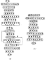
Fig. 8 is transmitter program flow diagram (a) mastery routine; (b) interrupt service routine.
Fig. 9 is receiver program flow diagram (a) mastery routine; (b) interrupt service routine.
This utility model is designed a kind of minitype digital cardiac telemetry monitor embodiment, and each ingredient is described in detail as follows respectively in conjunction with each accompanying drawing shown in Fig. 2-9:
Transmitter built-up circuit part:
Fig. 1 for the digital transmitter for ECG profile of adapted and with the electrode line chart that leads; three electrode slices 10 are affixed on the patient front; through the line 9 that leads; 8 receive joint 1; socket 2 enters transmitter main body 5, and patient's energized switch 7 can be launched electrocardiosignal; as unusually or not in good time, patient can be through button 6 nurse call.
Fig. 2 is the power converting circuit schematic diagram, wherein, and with amplifier IC
2: A7642 is connected into the voltage follower form, producing artificial mid point VG, uses for front end circuit, uses for follow-up digital circuit with the regulated power supply of 7805 regulator block generation+5V.
Fig. 3 is the preposition amplification of electrocardiosignal, filtering, level adjustment and the electrode inspection schematic diagram that comes off, wherein by IC
1Three amplifiers of A, B, C constitute the differential amplifier circuit of prestage high-gain, A, B are symmetric amplifiers, to obtain than high cmrr.Amplifier C carries out differential amplification, potentiometer P
1Be to establish for adjusting common mode rejection ratio, the characteristics that whole preposition difference is put level are input impedance height, the common mode rejection ratio height.When 20HZ tested, CMRR was about 81dB.The 50HZ trap circuit is made of the double T active circuit, by rationally selecting R for use
13, R
18, R
19, C
1, C
2, C
4, R
20, R
21Can obtain the very high trap characteristic of Q-value, get R
18=R
19, R
13=R
18, C
1=68000PF=C
2, C
4=2C
1, R
20=180K, R
21=200K records Q=5.In block isolating circuit, choose R
10, C
3Time constant is 2S.Amplifier IC
2: C serves as main putting with level and adjusts double effects, wherein, and potentiometer P
3Be used for amplification and regulate P
2Be used for the level adjustment, to obtain the analogue signal amount of 0-5V scope, amplifier IC
2: D constitutes the second order active low-pass filter, sets its cut-off frequency about 100HZ, desirable R
23=27K, C
7=4700PF, electrode come off check circuit by IC
1: D and audion, luminous tube L
1Etc. formation, IC
1: D is a comparator, and when electrode came off, it exported high level, the audion conducting, and luminous tube is luminous, and off signal triggering single-chip microcomputer is outer simultaneously interrupts 0, imports this information into the monitoring station.
Fig. 4 is Single-chip Controlling and A/D change-over circuit, by the single-chip microcomputer internal timing, obtains the sample rate of 200HZ.Simultaneously, single-chip microcomputer is the data processing of encoding, and send among the serial ports buffer SBUF, with the baud rate of setting, and serial output digital quantity.This part circuit is chip used to be all CMOS low-power consumption slice, thin piece, and the programme-control single-chip microcomputer enters the wait method of operation at any time, to reduce power consumption.The sheet choosing end CE of 27C32 is connected to the effective ALE of address strobe of 80C31.
Fig. 5 is a frequency modulation frequency modulation radiating circuit schematic diagram, constitute single order FSK modulation by cmos digital phase-locked loop circuit CD4046, decide the input voltage of voltage controlled oscillator by the break-make of Digital Signals analog switch, and then produce two kinds of different frequencies of oscillation, this circuit is adjusted at 10K and 20KHZ with frequency of oscillation, LM358:B sends into frequency modulation transmitter module IC after oscillator signal is amplified, and behind the frequency modulation frequency modulation signal is launched, and the distance of its emission coverage is by modulation voltage and supply voltage decision.Carrier frequency is 250MHZ.
The receiving card built-up circuit:
Fig. 6 is the anti-process of corresponding radiating circuit with Fig. 7, Fig. 6 is FM reception, demodulation and amplification and rectification circuit, wherein receiver module IC amplifies high-frequency signal, demodulate subcarrier signal, after amplifier is amplified, send into phaselocked loop 4046 and demodulate digital signal, and after the binary digital signal of standard is sent in amplification and Schmidt trigger shaping.
Fig. 7 is interface and decoding circuit, constitutes address decoding circuitry by phase inverter LS04, eight NAND gate LS07, determines the I/O port address of this receiving card, and bus driving circuits is made up of LS245, and the direction of control data stream.The 8250th, the asynchronous communication special chip, by to its programming, make it to receive serial data through oscillating circuit (OSC) by certain baud rate, and come the correctness of error detecting code position transmission, its inside to have the interrupt management function to trigger a certain outside of PC with certain rule to interrupt (as IRQ5) firmly and can realize communication with computer by its INT port.Host CPU just can be analyzed and handle its digital quantity that obtains this moment.
Fig. 8 is the software flow pattern of this monitor transmitter, it is made up of two parts, be mastery routine (a) and interrupt service routine (b), behind electric power starting, program among the EPROM brings into operation, through initialization intervalometer is set, middle fracture triggering mode, after the original state and parameter of serial ports etc., the opening timing device allows to interrupt, circular wait enters interrupt service routine (b), under the timing and interruption control of intervalometer 0, open A/D and carry out data acquisition by the sample rate of 200HZ, conversion is carried out the result that the baud rate with 2400b/s sends behind the date processing by single-chip microcomputer.
Fig. 9 is the software flow pattern of this monitor receiver, it also is made up of mastery routine (a) and interrupt service routine (b) two parts, because this plate is inserted in the notch of main frame, program main frame is thus carried out, in (a) mastery routine, at first carry out initialization, comprise pictorial display, open Chinese word library, menu, screen is provided with, interruption is opened in serial line interface working method and interrupt vector setting etc. then, receives keyboard operation and enter hardware interrupts service routine (b) in menu, the preservation environment is provided with, read interrupt status, the communication checking data is handled electrocardiogram (ECG) data in main frame, deposit relief area in, calculate heart rate, abnormality processing, mastery routine (a) is returned at the recovery scene then, recovers interrupt vector and other system close file is set.
Claims (3)
1, a kind of minitype digital cardiac telemetry monitor is made up of backpack transmitter and remote control receiving card two parts, and it is characterized in that: said transmitter comprises the exploring electrode of surveying electrocardiosignal; The electrocardiosignal preamplifier that detectable signal is amplified; Filtering and level adjusting circuit that the electrocardiosignal of amplifying is carried out filtering and adjustment; Adjusted analog signal conversion is become the A/D change-over circuit of digital signal; Single-chip microcomputer and peripheral circuit thereof that digital signal is handled and each circuit is controlled; Signal after handling through the single-chip microcomputer coding is carried out frequency give synthetic frequency shift keying (FSK) primary modulation circuit, the modulating emission circuit that again its signal is carried out frequency modulation for the second time and launch with high frequency carrier, and provide the power converting circuit of different voltages and to the electrode that said electrode signal the detects testing circuit that comes off for each circuit; Said receiving card comprises the reception amplifying circuit that the signal to transmitter emission receives and amplifies, this signal is demodulated to the FSK demodulator circuit of digital signal, its signal is amplified the amplification and rectification circuit of shaping, again to the signal after the shaping decode the decoding circuit that obtains electrocardiogram (ECG) data and with interface and the control circuit of these data being sent into the PC bus.
2, monitor as claimed in claim 1 is characterized in that the pre-amplification circuit in the said transmitter constitutes three amplifier differential amplifiers by the low-power consumption amplifier; Said filtering and shaping circuit comprise the filter circuit that is made of double T trap active circuit, the block isolating circuit that is made of resistance, electric capacity, level adjusting circuit that is made of amplifier and potentiometer and the second order active low-pass filter circuit that is made of amplifier; Said FSK single order modulation circuit is made of phaselocked loop.
3, monitor as claimed in claim 1 is characterized in that said receiving card adopts the expanded slot of computer plug connector, and FSK demodulator circuit wherein is made of phaselocked loop, and said decoding circuit is made up of the asynchronous communication special chip.
Priority Applications (1)
| Application Number | Priority Date | Filing Date | Title |
|---|---|---|---|
| CN 95208884 CN2216391Y (en) | 1995-04-28 | 1995-04-28 | Digital remote-controlling micro-cardioelectric monitoring instrument |
Applications Claiming Priority (1)
| Application Number | Priority Date | Filing Date | Title |
|---|---|---|---|
| CN 95208884 CN2216391Y (en) | 1995-04-28 | 1995-04-28 | Digital remote-controlling micro-cardioelectric monitoring instrument |
Publications (1)
| Publication Number | Publication Date |
|---|---|
| CN2216391Y true CN2216391Y (en) | 1996-01-03 |
Family
ID=33860065
Family Applications (1)
| Application Number | Title | Priority Date | Filing Date |
|---|---|---|---|
| CN 95208884 Expired - Fee Related CN2216391Y (en) | 1995-04-28 | 1995-04-28 | Digital remote-controlling micro-cardioelectric monitoring instrument |
Country Status (1)
| Country | Link |
|---|---|
| CN (1) | CN2216391Y (en) |
Cited By (9)
| Publication number | Priority date | Publication date | Assignee | Title |
|---|---|---|---|---|
| CN102637261A (en) * | 2012-04-11 | 2012-08-15 | 东莞市巨细信息科技有限公司 | An RFID electronic tag integrated with an electrocardiographic signal acquisition circuit |
| CN102961131A (en) * | 2012-11-26 | 2013-03-13 | 西安交大辰方科技有限公司 | Automatic detection and transformation method for loose of electrocardiograph limb electrodes |
| CN103006200A (en) * | 2012-12-24 | 2013-04-03 | 中国人民解放军第四军医大学 | Wireless detection device of small animals action potential |
| CN103784135A (en) * | 2012-11-02 | 2014-05-14 | 邱金和 | Portable ECG Measurement System |
| CN104000582A (en) * | 2014-05-04 | 2014-08-27 | 山东中医药大学 | Lead falling detection device for electrocardiogram monitoring device |
| CN104117148A (en) * | 2014-08-13 | 2014-10-29 | 深圳市是源医学科技有限公司 | Electrical stimulation system for hastening parturition through acupoint between shoulder and ta chuei |
| CN108568064A (en) * | 2018-04-17 | 2018-09-25 | 六盘水市人民医院 | A kind of intelligent breathing internal medicine lung function Training Control system |
| CN109975878A (en) * | 2017-12-27 | 2019-07-05 | 四川锦江电子科技有限公司 | It falls off the device and method of detection for three-dimensional mapping system body surface excitation electrode slice |
| CN112930145A (en) * | 2018-10-25 | 2021-06-08 | 皇家飞利浦有限公司 | Ultrasonic control unit |
-
1995
- 1995-04-28 CN CN 95208884 patent/CN2216391Y/en not_active Expired - Fee Related
Cited By (12)
| Publication number | Priority date | Publication date | Assignee | Title |
|---|---|---|---|---|
| CN102637261A (en) * | 2012-04-11 | 2012-08-15 | 东莞市巨细信息科技有限公司 | An RFID electronic tag integrated with an electrocardiographic signal acquisition circuit |
| CN102637261B (en) * | 2012-04-11 | 2015-02-18 | 东莞市巨细信息科技有限公司 | RFID electronic tag integrated with electrocardiosignal acquisition circuit |
| CN103784135A (en) * | 2012-11-02 | 2014-05-14 | 邱金和 | Portable ECG Measurement System |
| CN102961131A (en) * | 2012-11-26 | 2013-03-13 | 西安交大辰方科技有限公司 | Automatic detection and transformation method for loose of electrocardiograph limb electrodes |
| CN102961131B (en) * | 2012-11-26 | 2014-06-25 | 西安交大辰方科技有限公司 | Automatic detection and transformation method for loose of electrocardiograph limb electrodes |
| CN103006200A (en) * | 2012-12-24 | 2013-04-03 | 中国人民解放军第四军医大学 | Wireless detection device of small animals action potential |
| CN104000582A (en) * | 2014-05-04 | 2014-08-27 | 山东中医药大学 | Lead falling detection device for electrocardiogram monitoring device |
| CN104117148A (en) * | 2014-08-13 | 2014-10-29 | 深圳市是源医学科技有限公司 | Electrical stimulation system for hastening parturition through acupoint between shoulder and ta chuei |
| CN104117148B (en) * | 2014-08-13 | 2016-08-24 | 深圳市是源医学科技有限公司 | A kind of Jianjing point is hastened parturition electric stimulation |
| CN109975878A (en) * | 2017-12-27 | 2019-07-05 | 四川锦江电子科技有限公司 | It falls off the device and method of detection for three-dimensional mapping system body surface excitation electrode slice |
| CN108568064A (en) * | 2018-04-17 | 2018-09-25 | 六盘水市人民医院 | A kind of intelligent breathing internal medicine lung function Training Control system |
| CN112930145A (en) * | 2018-10-25 | 2021-06-08 | 皇家飞利浦有限公司 | Ultrasonic control unit |
Similar Documents
| Publication | Publication Date | Title |
|---|---|---|
| US6450953B1 (en) | Portable signal transfer unit | |
| CN2216391Y (en) | Digital remote-controlling micro-cardioelectric monitoring instrument | |
| CN201227272Y (en) | Dress type electro-cardio and respiration rate monitoring device based on Zigbee | |
| CN105796124B (en) | Mobile cardiophony system and method based on Internet of Things | |
| CN111887818A (en) | Intelligent vital sign monitoring and controlling system and method based on microwave radar | |
| CN202568244U (en) | Portable wireless electrocardio monitoring management system | |
| CN201022706Y (en) | Minitype portable remote multi-parameter monitor | |
| CN107490557A (en) | A kind of carbon dioxide detecting system based on Infrared spectra adsorption principle | |
| CN206557982U (en) | A kind of power marketing data acquisition device | |
| CN1493886A (en) | Radio battery voltage detection system | |
| CN209280821U (en) | A kind of outer electric energy quality monitoring, recording instrument of household portable | |
| CN201227282Y (en) | Dress type wireless heart-sound signal monitoring module based on Zigbee | |
| CN212788480U (en) | Remote medical detector | |
| CN2284072Y (en) | Portable microcomputer transfusion instrument | |
| CN201185922Y (en) | Electrocardiogram monitor system based on bluetooth communication | |
| CN203369902U (en) | Electrocardiogram monitoring system based on intelligent terminal communications | |
| CN203493620U (en) | Portable type multi-parameter collection terminal applied to mobile medical system | |
| CN217907812U (en) | Portable intelligent stethoscope | |
| CN210144670U (en) | A wireless heart murmur detection system | |
| CN203341737U (en) | Electroglottography instrument | |
| CN213750689U (en) | Intelligent instrument data information acquisition management and control system based on Internet of things and cloud platform | |
| CN2566802Y (en) | All-digital radio multi-channel cardiac telemetry system | |
| CN218512948U (en) | Broadband acquisition and analysis equipment | |
| CN214122752U (en) | BIM + GIS wisdom collection system with long-range sample function | |
| CN2783939Y (en) | Real time monitor for moving |
Legal Events
| Date | Code | Title | Description |
|---|---|---|---|
| C14 | Grant of patent or utility model | ||
| GR01 | Patent grant | ||
| C19 | Lapse of patent right due to non-payment of the annual fee | ||
| CF01 | Termination of patent right due to non-payment of annual fee |