CN219167451U - Quick-insertable center catheter insertion assembly and coupler assembly therefor - Google Patents
Quick-insertable center catheter insertion assembly and coupler assembly therefor Download PDFInfo
- Publication number
- CN219167451U CN219167451U CN202222569224.7U CN202222569224U CN219167451U CN 219167451 U CN219167451 U CN 219167451U CN 202222569224 U CN202222569224 U CN 202222569224U CN 219167451 U CN219167451 U CN 219167451U
- Authority
- CN
- China
- Prior art keywords
- needle
- coupler
- coupler housing
- extension arm
- assembly
- Prior art date
- Legal status (The legal status is an assumption and is not a legal conclusion. Google has not performed a legal analysis and makes no representation as to the accuracy of the status listed.)
- Active
Links
- 238000003780 insertion Methods 0.000 title claims description 64
- 230000037431 insertion Effects 0.000 title claims description 59
- 210000003813 thumb Anatomy 0.000 claims description 57
- 210000003811 finger Anatomy 0.000 claims description 23
- 238000003825 pressing Methods 0.000 claims description 15
- 238000007789 sealing Methods 0.000 claims description 8
- 231100000435 percutaneous penetration Toxicity 0.000 claims description 6
- 230000008878 coupling Effects 0.000 claims description 5
- 238000010168 coupling process Methods 0.000 claims description 5
- 238000005859 coupling reaction Methods 0.000 claims description 5
- 238000000034 method Methods 0.000 description 31
- 239000008280 blood Substances 0.000 description 22
- 210000004369 blood Anatomy 0.000 description 22
- 239000000463 material Substances 0.000 description 17
- 229920002635 polyurethane Polymers 0.000 description 8
- 239000004814 polyurethane Substances 0.000 description 8
- 210000004204 blood vessel Anatomy 0.000 description 6
- 230000000694 effects Effects 0.000 description 6
- -1 polytetrafluoroethylene Polymers 0.000 description 6
- 210000005166 vasculature Anatomy 0.000 description 6
- 239000004599 antimicrobial Substances 0.000 description 5
- 238000012800 visualization Methods 0.000 description 5
- 208000027418 Wounds and injury Diseases 0.000 description 4
- 230000007704 transition Effects 0.000 description 4
- 230000002792 vascular Effects 0.000 description 4
- 238000003466 welding Methods 0.000 description 4
- 238000004804 winding Methods 0.000 description 4
- XSTXAVWGXDQKEL-UHFFFAOYSA-N Trichloroethylene Chemical compound ClC=C(Cl)Cl XSTXAVWGXDQKEL-UHFFFAOYSA-N 0.000 description 3
- 230000000712 assembly Effects 0.000 description 3
- 238000000429 assembly Methods 0.000 description 3
- 238000011109 contamination Methods 0.000 description 3
- 150000002009 diols Chemical class 0.000 description 3
- 239000012530 fluid Substances 0.000 description 3
- 239000002861 polymer material Substances 0.000 description 3
- 230000000284 resting effect Effects 0.000 description 3
- 239000002904 solvent Substances 0.000 description 3
- 239000004698 Polyethylene Substances 0.000 description 2
- 239000004743 Polypropylene Substances 0.000 description 2
- 238000004026 adhesive bonding Methods 0.000 description 2
- 208000014674 injury Diseases 0.000 description 2
- 229920000573 polyethylene Polymers 0.000 description 2
- 229920001155 polypropylene Polymers 0.000 description 2
- 229920001343 polytetrafluoroethylene Polymers 0.000 description 2
- 239000004810 polytetrafluoroethylene Substances 0.000 description 2
- 230000008733 trauma Effects 0.000 description 2
- 206010000060 Abdominal distension Diseases 0.000 description 1
- 230000006978 adaptation Effects 0.000 description 1
- 239000000654 additive Substances 0.000 description 1
- 239000000853 adhesive Substances 0.000 description 1
- 230000001070 adhesive effect Effects 0.000 description 1
- 230000000845 anti-microbial effect Effects 0.000 description 1
- 230000017531 blood circulation Effects 0.000 description 1
- 230000036760 body temperature Effects 0.000 description 1
- 239000011248 coating agent Substances 0.000 description 1
- 238000000576 coating method Methods 0.000 description 1
- 230000006835 compression Effects 0.000 description 1
- 238000007906 compression Methods 0.000 description 1
- 238000005520 cutting process Methods 0.000 description 1
- 238000000502 dialysis Methods 0.000 description 1
- 230000009977 dual effect Effects 0.000 description 1
- 239000012943 hotmelt Substances 0.000 description 1
- 238000001727 in vivo Methods 0.000 description 1
- 230000007794 irritation Effects 0.000 description 1
- 230000000813 microbial effect Effects 0.000 description 1
- 238000012986 modification Methods 0.000 description 1
- 230000004048 modification Effects 0.000 description 1
- 208000001297 phlebitis Diseases 0.000 description 1
- 229920000642 polymer Polymers 0.000 description 1
- 229920001296 polysiloxane Polymers 0.000 description 1
- 229920000915 polyvinyl chloride Polymers 0.000 description 1
- 239000004800 polyvinyl chloride Substances 0.000 description 1
- 230000002885 thrombogenetic effect Effects 0.000 description 1
Images


Classifications
-
- A—HUMAN NECESSITIES
- A61—MEDICAL OR VETERINARY SCIENCE; HYGIENE
- A61M—DEVICES FOR INTRODUCING MEDIA INTO, OR ONTO, THE BODY; DEVICES FOR TRANSDUCING BODY MEDIA OR FOR TAKING MEDIA FROM THE BODY; DEVICES FOR PRODUCING OR ENDING SLEEP OR STUPOR
- A61M39/00—Tubes, tube connectors, tube couplings, valves, access sites or the like, specially adapted for medical use
- A61M39/10—Tube connectors; Tube couplings
-
- A—HUMAN NECESSITIES
- A61—MEDICAL OR VETERINARY SCIENCE; HYGIENE
- A61M—DEVICES FOR INTRODUCING MEDIA INTO, OR ONTO, THE BODY; DEVICES FOR TRANSDUCING BODY MEDIA OR FOR TAKING MEDIA FROM THE BODY; DEVICES FOR PRODUCING OR ENDING SLEEP OR STUPOR
- A61M25/00—Catheters; Hollow probes
- A61M25/01—Introducing, guiding, advancing, emplacing or holding catheters
- A61M25/06—Body-piercing guide needles or the like
- A61M25/0606—"Over-the-needle" catheter assemblies, e.g. I.V. catheters
-
- A—HUMAN NECESSITIES
- A61—MEDICAL OR VETERINARY SCIENCE; HYGIENE
- A61M—DEVICES FOR INTRODUCING MEDIA INTO, OR ONTO, THE BODY; DEVICES FOR TRANSDUCING BODY MEDIA OR FOR TAKING MEDIA FROM THE BODY; DEVICES FOR PRODUCING OR ENDING SLEEP OR STUPOR
- A61M25/00—Catheters; Hollow probes
- A61M25/01—Introducing, guiding, advancing, emplacing or holding catheters
- A61M25/09—Guide wires
-
- A—HUMAN NECESSITIES
- A61—MEDICAL OR VETERINARY SCIENCE; HYGIENE
- A61M—DEVICES FOR INTRODUCING MEDIA INTO, OR ONTO, THE BODY; DEVICES FOR TRANSDUCING BODY MEDIA OR FOR TAKING MEDIA FROM THE BODY; DEVICES FOR PRODUCING OR ENDING SLEEP OR STUPOR
- A61M25/00—Catheters; Hollow probes
- A61M25/01—Introducing, guiding, advancing, emplacing or holding catheters
- A61M25/06—Body-piercing guide needles or the like
- A61M25/065—Guide needles
Landscapes
- Health & Medical Sciences (AREA)
- Life Sciences & Earth Sciences (AREA)
- Heart & Thoracic Surgery (AREA)
- Hematology (AREA)
- Anesthesiology (AREA)
- Biomedical Technology (AREA)
- Engineering & Computer Science (AREA)
- Pulmonology (AREA)
- Animal Behavior & Ethology (AREA)
- General Health & Medical Sciences (AREA)
- Public Health (AREA)
- Veterinary Medicine (AREA)
- Biophysics (AREA)
- Media Introduction/Drainage Providing Device (AREA)
Abstract
The present application relates to a quick-insertable central catheterization assembly and a coupler assembly therefor. For example, the coupler assembly may include an introducer needle and a coupler coupled together. The introducer needle may include a needle hub over the needle shaft and a sheath over the needle shaft. The needle shaft may include a longitudinal needle slot extending through the distal needle tip. The sheath may seal the needle slot therebelow, except for the needle slot below the sheath opening in the proximal portion of the sheath. The needle hub may include a needle hub clamp. The coupler may include a coupler housing and an extension arm connected to the coupler housing. The needle hub clamp may clamp onto the coupler housing at least in an immediate deployment state of the coupler assembly. The extension arm may be configured for attaching a proximal end of an access guidewire thereto.
Description
Priority
U.S. provisional application No. 63/249,009, filed on day 27 of 9 at 2021; U.S. provisional application No. 63/271,043 filed on 10/22 of 2021; and U.S. provisional application No. 63/318,945, filed on day 3 and 11 of 2022, each of which is incorporated herein by reference in its entirety.
Technical Field
The present application relates to the field of medical devices, and more particularly to a quick-insertable central catheterization assembly and a coupler assembly therefor.
Background
Central venous catheters ("CVCs") are typically introduced into a patient and advanced through their vasculature by the zetidine technique. The zetidine technique utilizes a number of steps and medical devices (e.g., needles, scalpels, guidewires, introducer sheaths, dilators, CVCs, etc.). Although the zetidine technique is effective, the number of steps is time consuming, handling a large number of medical devices is difficult, and both can cause trauma to the patient. In addition, there is a relatively high likelihood of contact contamination due to the number of medical devices that need to be replaced during the zetidine technique. Accordingly, there is a need to reduce the number of steps and medical devices involved in introducing a catheter (e.g., a CVC) into a patient and advancing the catheter through its vasculature.
Disclosed herein are couplers for quick-insertable center catheters ("RICCs") and assemblies thereof that address the above-described problems.
Disclosure of Invention
Disclosed herein is a RICC insertion assembly, in some embodiments, comprising a RICC, an introducer needle, an access guidewire, and a coupler coupling the RICC, introducer needle, and access guidewire together. The introducer needle includes a needle shaft, a sheath over the needle shaft, and a needle hub over both the needle shaft and the sheath. The needle shaft includes a longitudinal needle slot extending from a proximal portion of the needle shaft through the distal needle tip. The sheath is located over the needle shaft, sealing the needle slot thereunder, except for the needle slot below the sheath opening in the proximal portion of the sheath. The needle hub is over the proximal portion of the sheath and the needle shaft. The access guidewire includes a proximal portion having a proximal end and a distal portion having a distal end. At least in the immediate deployment state of the RICC insertion assembly, the distal end of the access guidewire is disposed in the introducer needle just proximal of the needle tip. The coupler includes a coupler housing and an extension arm connected to the coupler housing. At least in an immediate deployment state of the RICC insert assembly, the securing means for securing the needle hub to the coupler housing secures the needle hub to the coupler housing. In addition, at least in the immediate deployment state of the RICC insertion assembly, the proximal end of the access guidewire is attached to the extension arm. The proximal and distal ends of the access guidewire implement a loop in the access guidewire over which the RICC is disposed at least in an immediate deployment state of the RICC insertion assembly.
In some embodiments, the securing means for securing the needle hub to the coupler housing is a needle hub clamp. The needle hub clamp is clamped to the coupler housing at least in an immediate deployment state of the RICC insert assembly.
In some embodiments, the needle hub clamp is integral with the needle hub.
In some embodiments, the needle hub clamp includes a single lever clamp arm that extends distally beyond the needle hub from a fulcrum that connects the clamp arm to the remainder of the needle hub. The clip arms include a protrusion extending from a distal portion thereof that is configured to engage with a recess in a corresponding side of the coupler housing when the clip arms are clamped to the coupler housing. The protrusion is further configured to disengage from a recess in a corresponding side of the coupler housing when the proximal portion of the clip arm is pressed in toward the centerline of the needle hub.
In some embodiments, the needle hub clamp includes a pair of lever clamp arms extending distally on opposite sides of the needle hub from corresponding pairs of fulcrums connecting the clamp arms to the remainder of the needle hub. Each clip arm of the pair of clip arms includes a protrusion extending from a distal portion thereof that is configured to engage with a recess in a corresponding side of the coupler housing to clamp the needle hub on the coupler housing. The protrusion is further configured to disengage from a recess in a corresponding side of the coupler housing when the proximal portion of the clip arm is pressed toward the centerline of the needle hub.
In some embodiments, the coupler housing includes a longitudinal coupler housing slot in a side of the coupler housing opposite the extension arm. The coupler housing slot opens in the same direction as the needle slot of the needle shaft. The coupler housing slot is configured to allow the access guidewire to disengage from the coupler housing (escape) during withdrawal of the introducer needle from the coupler through the needle hub.
In some embodiments, the coupler housing includes a thumb depression in a side of the coupler housing that includes a coupler housing slot. The thumb depression is configured for thumb pressing against an access guidewire therein to hold the access guidewire in place at least during percutaneous penetration with the introducer needle or withdrawal of the introducer needle from the coupler through the needle hub.
In some embodiments, the coupler housing slot extends partially into the thumb depression such that the distal portion of the access guidewire extends into the thumb depression, at least in the state of the immediate deployment state of the RICC insert assembly.
In some embodiments, the surface of the thumb depression is textured.
In some embodiments, the coupler housing includes a finger recess in a side of the coupler housing opposite the thumb recess. The finger recess is configured for holding the RICC insert assembly with the finger while pressing the access guidewire with the thumb into the thumb recess at least during percutaneous penetration with the introducer needle or withdrawal of the introducer needle from the coupler through the needle hub.
In some embodiments, the extension arm is integral with the coupler housing.
In some embodiments, the extension arm terminates in an extension arm clip that clips onto the luer connector of the RICC, at least in the immediate deployment state of the RICC insert assembly. The proximal portion of the access guidewire extends from the luer connector, through the center of the extension arm clamp, and to the guidewire attachment point of the extension arm, to which the proximal end of the access guidewire is attached.
In some embodiments, the extension arm clamp includes a socket into which the proximal end of the luer connector of the RICC is inserted when the extension arm clamp is clamped over the luer connector.
In some embodiments, the extension arm includes an extension arm opening through opposite sides of the extension arm between the extension arm clamp and a connection portion of the extension arm that connects the extension arm to the remainder of the coupler housing. The extension arm opening is configured to provide a window through which the access guidewire is visualized to confirm that the access guidewire is attached to the guidewire attachment point of the extension arm.
In some embodiments, the connector housing includes a needle hub receiver in a proximal portion of the connector housing into which a distal portion of the needle hub is inserted, at least in an immediate deployment state of the RICC insertion assembly.
In some embodiments, the coupler further comprises a valve module disposed in the valve module compartment of the coupler housing. At least in the immediate deployment state of the RICC insertion assembly, the valve module seals around the proximal portion of the sheath and the distal portion of the access guidewire extending through the sheath opening, thereby enabling leak-free aspiration through the introducer needle.
In some embodiments, the valve module includes an integrated blade disposed in the needle slot below the distal end of the sheath opening. The blade includes a distally facing blade edge configured to cut the sheath from the needle shaft during withdrawal of the introducer needle from the coupler through the needle hub, thereby allowing the access guidewire to disengage from the needle shaft through the needle slot of the needle shaft.
In some embodiments, the ric insertion assembly further comprises a syringe fluidly coupled to the introducer needle at least in an immediate deployment state of the ric insertion assembly.
Also disclosed herein is a coupler assembly for a RICC insertion assembly, which in some embodiments includes an introducer needle and a coupler coupled together. The introducer needle includes a needle shaft, a sheath over the needle shaft, and a needle hub over both the needle shaft and the sheath. The needle shaft includes a longitudinal needle slot extending from a proximal portion of the needle shaft through the distal needle tip. The sheath is located over the needle shaft, sealing the needle slot thereunder, except for the needle slot below the sheath opening in the proximal portion of the sheath. The needle hub is over the proximal portion of the sheath and the needle shaft. The needle hub includes a needle hub clamp. The coupler includes a coupler housing and an extension arm connected to the coupler housing. The needle hub clamp is clamped to the coupler housing at least in an immediate deployment state of the coupler assembly. The extension arm is configured for attaching a proximal end of an access guidewire thereto.
In some embodiments, the needle hub clamp includes a pair of lever clamp arms extending distally on opposite sides of the needle hub from corresponding pairs of fulcrums connecting the clamp arms to the remainder of the needle hub. Each clip arm of the pair of clip arms includes a protrusion extending from a distal portion thereof that is configured to engage with a recess in a corresponding side of the coupler housing to clamp the needle hub on the coupler housing. The protrusion is further configured to disengage from a recess in a corresponding side of the coupler housing when the proximal portion of the clip arm is pressed toward the centerline of the needle hub.
In some embodiments, the coupler housing includes a longitudinal coupler housing slot in a side of the coupler housing opposite the extension arm. The coupler housing slot opens in the same direction as the needle slot of the needle shaft. The coupler housing slot is configured to allow the access guidewire to disengage from the coupler housing when the access guidewire is disposed therein.
In some embodiments, the coupler housing includes a thumb depression in a side of the coupler housing that includes the coupler housing slot such that the coupler housing slot extends partially into the thumb depression. The thumb depression is configured for thumb pressing against the access guidewire therein to hold the access guidewire in place when the access guidewire is disposed in the coupler housing.
In some embodiments, the coupler housing includes a finger recess in a side of the coupler housing opposite the thumb recess. The finger recess is configured to hold the coupler assembly with a finger while pressing the access guidewire with a thumb into the thumb recess when the access guidewire is disposed in the coupler housing.
In some embodiments, the extension arm terminates in an extension arm clip configured as a socket into which the proximal end of the luer connector of the RICC is inserted to clip the extension arm clip onto the luer connector.
In some embodiments, the extension arm includes an extension arm opening through opposite sides of the extension arm between the extension arm clamp and a connection portion of the extension arm that connects the extension arm to the remainder of the coupler housing. The extension arm opening is configured to provide a window through which the access guidewire is visualized to confirm that the access guidewire is attached to the guidewire attachment point of the extension arm when the access guidewire should be attached to the guidewire attachment point.
In some embodiments, the connector housing includes a needle hub receiver in a proximal portion of the connector housing into which a distal portion of the needle hub is inserted, at least in an immediate deployment state of the RICC insertion assembly.
In some embodiments, the coupler further comprises a valve module disposed in the valve module compartment of the coupler housing. When the access guidewire extends through the sheath opening, the valve module seals around the proximal portion of the sheath and the access guidewire, thereby enabling leak-free aspiration through the introducer needle.
In some embodiments, the valve module includes an integrated blade disposed in the needle slot below the distal end of the sheath opening. The blade includes a distally facing blade edge configured to cut the sheath from the needle shaft during withdrawal of the introducer needle from the coupler through the needle hub.
Also disclosed herein is a method for inserting a RICC into a vascular lumen of a patient. In some embodiments, the method comprises a RICC insertion assembly obtaining step, a needle tract establishing step, an access guidewire advancing step, a clip opening step, an introducer needle withdrawing step, and a RICC advancing step. The rich insert obtaining step includes obtaining a rich insert. The RICC insertion assembly includes a RICC coupled together by a coupler, an introducer needle including a sheath over a needle shaft, and an access guidewire. The proximal end of the access guidewire is coupled to the extension arm of the coupler. The distal end of the access guidewire is disposed in the introducer needle through a valve module of the coupler. The proximal and distal ends of the access guidewire implement a loop in the access guidewire over which the RICC is disposed at least in an immediate deployment state of the RICC insertion assembly. The needle track establishing step includes establishing a needle track from the skin area to the lumen of the blood vessel with an introducer needle. The entry guidewire advancing step includes advancing the distal end of the entry guidewire into the lumen of the vessel from its initial position in the needle shaft just proximal to the tip of the needle shaft. The clip opening step includes pressing the pair of lever clip arms toward the center line of the needle hub of the introducer needle. Pressing the pair of clip arms inwardly toward the needle hub disengages each clip arm of the pair of clip arms from the coupler housing of the coupler, the clip arms extending distally over the coupler housing. The introducer needle withdrawing step includes withdrawing the introducer needle from the coupler through the needle hub, leaving the access guidewire in place in the lumen of the vessel. The introducer needle includes a longitudinal needle slot extending from a proximal portion of the needle shaft through the needle tip. The needle slot allows the access guidewire to be disengaged therefrom as the introducer needle is withdrawn from the coupler. The rich advancing step includes advancing a catheter tube of the rich over the access guidewire to insert the rich into the vessel lumen.
In some embodiments, the method further comprises a blood aspiration step. The blood aspiration step includes aspirating blood with a syringe coupled to the needle hub to confirm that the needle tract extends into the vessel lumen. The sheath is positioned over the needle shaft and seals the needle slot therebelow to aspirate blood with the syringe. The blood aspiration step is performed prior to the introducer needle withdrawal step.
In some embodiments, the introducer needle withdrawing step includes simultaneously resecting the sheath from the needle shaft with an integrated blade of a valve module disposed in a valve module compartment of the coupler housing. The removal of the sheath from the needle shaft allows the access guidewire to be detached from the needle shaft through its needle slot.
In some embodiments, the coupler housing includes a longitudinal coupler housing slot in a side of the coupler housing opposite the extension arm. The coupler housing slot opens in the same direction as the needle slot of the needle shaft. The coupler housing slot is configured to allow the access guidewire to disengage from the coupler housing during the introducer needle withdrawal step.
In some embodiments, the method further comprises entering a guidewire fixation step. The access guidewire securing step includes pressing the access guidewire with a thumb into a thumb depression in a side of the coupler housing including the coupler housing slot. Pressing the access guidewire into the thumb depression holds the access guidewire in place during the track establishment step or the introducer needle withdrawal step.
In some embodiments, the method further comprises an access guidewire visualization step. The access guidewire visualization step includes visualizing an access guidewire in the opening of the extension arm. The extension arm opening passes through opposite sides of the extension arm between a proximal end of the extension arm and a connection portion of the extension arm that connects the extension arm to the remainder of the coupler housing. The access guidewire is visualized to confirm that the access guidewire is attached to the guidewire attachment point of the extension arm.
In some embodiments, the method further comprises a RICC decoupling step. The rich decoupling step includes removing the luer connector of the rich from the extension arm clamp of the extension arm during the rich advancing step, thereby decoupling the rich from the coupler during the remainder of the rich advancing step. The coupler or its extension arm becomes the handle for the access guidewire.
These and other features of the concepts provided herein will become more readily apparent to those skilled in the art in view of the drawings and the following description, which describe in more detail certain embodiments of such concepts.
Drawings
FIG. 1 illustrates a side view of a RICC insert assembly according to some embodiments.
Fig. 2 illustrates a side view of a coupler assembly according to some embodiments.
Fig. 3 illustrates a top view of a coupler assembly according to some embodiments.
Fig. 4 illustrates a bottom view of a coupler assembly, according to some embodiments.
Fig. 5 illustrates a side view of a coupler assembly with an introducer needle withdrawn from a coupler, according to some embodiments.
Fig. 6 illustrates a longitudinal cross-section of a coupler assembly according to some embodiments.
Fig. 7 illustrates a longitudinal cross section of a coupler assembly according to some embodiments.
Fig. 8 illustrates a longitudinal cross-section of an introducer needle of a coupling assembly in accordance with some embodiments.
Fig. 9 illustrates a side view of an introducer needle in accordance with some embodiments.
Fig. 10 illustrates a top view of an introducer needle in accordance with some embodiments.
Fig. 11 illustrates a top view of a sheath over a needle shaft as in an introducer needle, according to some embodiments.
Fig. 12 illustrates a top view of a sheath according to some embodiments.
Fig. 13 illustrates a top view of a needle shaft according to some embodiments.
FIG. 14 illustrates a RICC of a RICC insert assembly according to some embodiments.
Fig. 15 illustrates a detailed view of a distal portion of a catheter tube of a RICC according to some embodiments.
Fig. 16 illustrates a transverse cross-section of a distal portion of a catheter tube according to some embodiments.
Fig. 17 illustrates another transverse cross-section of a distal portion of a catheter tube according to some embodiments.
Fig. 18 illustrates a longitudinal cross-section of a distal portion of a catheter tube according to some embodiments.
Detailed Description
Before some specific embodiments are disclosed in greater detail, it is to be understood that the specific embodiments disclosed herein are not limiting the scope of the concepts provided herein. It should also be understood that a particular embodiment disclosed herein may have features that are readily separable from the particular embodiment and that are optionally combined with or substituted for features of any of the many other embodiments disclosed herein.
With respect to the terms used herein, it is also to be understood that these terms are for the purpose of describing some particular embodiments and that these terms do not limit the scope of the concepts provided herein. Ordinal numbers (e.g., first, second, third, etc.) are generally used to distinguish or identify different features or steps in a set of features or steps, and do not provide a sequential or numerical limitation. For example, the "first," "second," and "third" features or steps need not necessarily occur in that order, and particular embodiments including such features or steps need not necessarily be limited to three features or steps. For convenience, labels such as "left", "right", "top", "bottom", "front", "rear", etc. are used and are not intended to imply any particular fixed position, orientation or direction, for example. Rather, such indicia are used to reflect, for example, relative position, orientation, or direction. The singular forms "a," "an," and "the" include plural referents unless the context clearly dictates otherwise.
Reference to, for example, "proximal", "proximal portion" or "proximal portion" of the catheter includes portions of the catheter that are intended to be proximal to a clinician when the catheter is used with a patient. Likewise, for example, the "proximal length" of the catheter includes the length of the catheter that is intended to be proximal to the clinician when the catheter is used on a patient. For example, the "proximal end" of a catheter includes the end of the catheter that is intended to be close to the clinician when the catheter is used on a patient. The proximal portion, or proximal length of the catheter may include the proximal end of the catheter; however, the proximal portion, or proximal length of the catheter need not include the proximal end of the catheter. That is, unless the context suggests otherwise, the proximal portion, or proximal length of the catheter is not the tip portion or tip length of the catheter.
Reference to, for example, "distal", "distal portion" or "distal portion" of the catheter includes portions of the catheter that are intended to be near or within the patient when the catheter is used with the patient. Likewise, for example, the "distal length" of a catheter includes the length of the catheter that is intended to be near or within the patient when the catheter is used with the patient. For example, the "distal end" of a catheter includes the end of the catheter that is intended to be near or within the patient when the catheter is used with the patient. The distal portion, or distal length of the catheter may comprise the distal end of the catheter; however, the distal portion, or distal length of the catheter need not include the distal end of the catheter. That is, unless the context suggests otherwise, the distal portion, or distal length of the catheter is not the tip portion or tip length of the catheter.
Unless defined otherwise, all technical and scientific terms used herein have the same meaning as commonly understood by one of ordinary skill in the art.
As described above, with regard to the zetidine technique, the number of steps is time consuming, handling a large number of medical devices is inconvenient, and both of these may result in patient trauma. In addition, there is a relatively high likelihood of contact contamination due to the number of medical devices that need to be replaced during the zetidine technique. Accordingly, there is a need to reduce the number of steps and medical devices involved in introducing a catheter (e.g., a CVC) into a patient and advancing the catheter through its vasculature.
Disclosed herein are couplers for quick insertable center catheters ("RICCs") and assemblies thereof. For example, the coupler assembly may include an introducer needle and a coupler coupled together. The introducer needle may include a needle hub over the needle shaft and a sheath over the needle shaft. The needle shaft may include a longitudinal needle slot extending through the distal needle tip. The sheath may seal the needle slot therebelow except for the needle slot below the sheath opening in the proximal portion of the sheath. The needle hub may include a needle hub clamp. The coupler may include a coupler housing and an extension arm connected to the coupler housing. The needle hub clamp may clamp onto the coupler housing at least in an immediate deployment state of the coupler assembly. The extension arm may be configured for attaching a proximal end of an access guidewire thereto.
The above-described features, as well as other features of the coupling for a RICC and its components, will become more apparent to those skilled in the art in view of the drawings and the following description, which describe the foregoing particular embodiments in the context of a RICC insert assembly. Notably, the RICC insert assembly is but one type of catheter that may be incorporated into a catheter insert assembly similar to the RICC insert assemblies provided herein. In practice, peripherally inserted central catheters ("PICCs"), dialysis catheters, etc. may also be incorporated into the catheterization assembly.
RICC insert assembly
FIG. 1 illustrates a RICC insert assembly 100 according to some embodiments.
As shown, RICC insert assembly 100 includes RICC 102, introducer needle 104, access guidewire 106, and coupler 108 coupling RICC 102, introducer needle 104, and access guidewire 106 together at least in the immediate deployment state of RICC insert assembly 100. Notably, as described below, the proximal end of the access guidewire 106 is attached to the extension arm 178 of the coupler 108, and the distal end of the access guidewire 106 is disposed within the needle lumen 156 of the introducer needle 104. This achieves a loop in the access guidewire 106. RiCC 102 is disposed over the ring in the immediate deployment state of RICC insert assembly 100 to maintain RICC insert assembly 100 in a relatively compact form.
Finally, any component of the ric insertion assembly 100 selected from at least the ric 102, the introducer needle 104, the access guidewire 106, the coupler 108, and the syringe 110, or any portion of a component selected from the foregoing components, may include an antimicrobial agent thereon or therein. In one embodiment, catheter tube 112 of rich 102 may include an antimicrobial coating on a abluminal surface (abluminal surface) of catheter tube 112, a luminal surface (lumen surface) of catheter tube 112, or both. In another embodiment, the pre-extruded material of the catheter tubing 112 may include an antimicrobial agent mixed therein such that the antimicrobial agent is incorporated into the catheter tubing 112 when extruded, the antimicrobial agent protecting both the abluminal surface of the catheter tubing 112 and the luminal surface of the catheter tubing 112 from microbial contamination.
FIG. 14 illustrates RICC 102 of RICC insert assembly 100 according to some embodiments.
As shown, RICC 102 includes a catheter tube 112, a catheter hub 114, one or more extension legs 116, and one or more extension leg connectors 118.
Figures 15-18 illustrate various views of catheter tube 112 of rich 102 according to some embodiments.
The catheter tube 112 includes a first section 120 in the distal portion of the catheter tube 112, a second section 122 proximal to the first section 120 in the distal portion of the catheter tube 112, and a tapered junction 124 between the first section 120 and the second section 122 of the catheter tube 112.
The first section 120 of the catheter tube 112 includes a catheter tip 126 having a relatively short taper from an outer diameter of a distal portion of the first section 120 distal of the junction 124 to an outer diameter of a distal end of the first section 120. The tapered configuration of catheter tip 126 serves to immediately dilate tissue surrounding the needle tract created with introducer needle 104 until the outer diameter of the distal portion of first section 120 of catheter tube 112. As best shown in fig. 18, the first section 120 of the catheter tube 112 further includes a proximal portion that is disposed in a bore of a distal portion of the joint 124 and fixedly coupled thereto, such as by solvent bonding, adhesive bonding, or thermal welding.
The second section 122 of the catheter tube 112 includes an outer diameter that is uniform over its length from the distal end of the second section 122 to the proximal end of the second section 122. The uniform diameter of the second section 122 of the catheter tubing 112 is configured for smooth insertion into the needle tract and target vasculature following any expansion of the first section 120 and the junction 124 of the catheter tubing 112. The distal end of the second section 122 of the catheter tube 112 has a flat surface flush with the flat proximal end of the joint 124 and is fixedly coupled thereto, such as by solvent bonding, adhesive bonding, or thermal welding.
The engagement portion 124 includes a taper over its length from the proximal end of the engagement portion 124 to the distal end of the engagement portion 124. The tapered configuration of the junction 124 serves to immediately expand tissue surrounding the needle tract from the outer diameter of the proximal portion of the first section 120 of the catheter tube 112 to the outer diameter of the second section 122 of the catheter tube 112. The abluminal surface of the junction 124 smoothly transitions from the abluminal surface of the first section 120 of the catheter tube 112 to the abluminal surface of the second section 122 of the catheter tube 112 without catching the edge of the skin when the catheter tube 112 is inserted into the needle tract. In addition to the edges being minimal to negligible, the edges may include solvent interdiffusion polymeric material that forms the polymeric material of the conduit tube 112, which smoothes the transition from the first section 120 of the conduit tube 112 to the junction 124 and from the junction 124 to the second section 122 of the conduit tube 112. Notably, the junction 124 has a length approximately comparable to the length of the exposed portion of the first section 120 of the conduit fitting 112, or between the lengths of the exposed portions of the first and second sections 120, 122 of the conduit fitting 112. Thus, the length of the exposed portion of the first section 120 of the catheter tube 112 is less than the length of the junction 124 until approximately the same length as the junction 124.
The first section 120 of the catheter tube 112 is formed of a first polymeric material (e.g., polytetrafluoroethylene, polypropylene, or polyurethane) having a first hardness. The second section 122 of the catheter tube 112 is formed of a second polymeric material (e.g., polyvinyl chloride, polyethylene, another polyurethane, or silicone) having a second hardness that is less than the first hardness. For example, the first section 120 of the conduit tube 112 may be formed from a first polyurethane having a first hardness, while the second section 122 of the conduit tube 112 may be formed from a second, different polyurethane having a second hardness that is less than the first hardness (e.g., the same or different di-or triisocyanate that reacts with a different diol or triol, a different di-or triisocyanate that reacts with the same or different diol or triol, the same di-or triisocyanate that reacts with the same diol or triol under different conditions, or with different additives, etc.). In fact, polyurethane is advantageous for catheter tubing 112 because polyurethane can be relatively rigid at room temperature, but becomes more flexible in vivo at body temperature, which reduces irritation of the vessel wall and phlebitis. Polyurethane also has the advantage that it can be less thrombogenic than some other polymers. The joint 124 is formed from a second polymeric material or a third polymeric material (e.g., yet another polyurethane) having a third hardness that is less than the first hardness and greater than, substantially equal to, or less than the second hardness.
It should be appreciated that the first hardness of the first polymeric material, the second hardness of the second polymeric material, and the third hardness of the third polymeric material may have different grades (e.g., type a or type D). With this understanding, when the second hardness or the third hardness is less than the first hardness, the second hardness of the second polymer material or the third hardness of the third polymer material may be not less in value than the first hardness of the first polymer material. In practice, the hardness of the second or third polymeric material may still be less than the hardness of the first polymeric material, as different grades, each ranging from 0 to 100, are designed for characterizing different materials in a group of materials having similar hardness.
According to the first section 120 of the catheter tube 112, the second section 122 of the catheter tube 112, and the junction 124 between the first section 120 and the second section 122 of the catheter tube 112 described above, the catheter tube 112 has sufficient breaking strength to prevent buckling of the catheter tube 112 when inserted into the needle tract created by the introducer needle 104. The fracture strength of the catheter tubing 112 is also sufficient to prevent buckling of the catheter tubing 112 as it is advanced through the vasculature of the patient without prior distention of the tissue surrounding the needle tract or any blood vessels of the vasculature with a separate dilator.
The catheter tubing 112 includes one or more catheter tubing lumens extending through the catheter tubing 112; however, in a multi-lumen ric (e.g., dual lumen ric, triple lumen ric, quad lumen ric, five lumen ric, six lumen ric, etc.), typically only one catheter tube lumen extends from the proximal end of catheter tube 112 to the distal end of catheter tube 112. In practice, the first section 120 of the catheter tube 112 generally includes a single lumen therethrough, as shown in fig. 15-18.
The catheter hub 114 is coupled to a proximal portion of the catheter tube 112. Catheter hub 114 includes one or more catheter hub lumens corresponding in number to the one or more catheter tube lumens. The one or more catheter hub lumens extend through the entire catheter hub 114 from the proximal end of the catheter hub 114 to the distal end of the catheter hub 114.
Each of the one or more extension legs 116 is coupled by its distal portion to the catheter hub 114. The one or more extension legs 116 each include one or more extension leg lumens that in turn correspond in number to the one or more catheter hub lumens. Each of the one or more extension leg lumens extends through the entire extension leg from a proximal end of the extension leg to a distal end of the extension leg.
Each of the one or more extension leg connectors 118 is located over a proximal portion of one of the one or more extension legs 116. For example, each of the one or more extension leg connectors 118 may be a luer connector over a proximal portion of one of the one or more extension legs 116. By means of such an extension leg connector, the corresponding extension leg and its extension leg lumen may be connected to another medical device and its lumen. However, at least in the immediate deployment state of the ric insertion assembly 100, at least one extension leg connector (e.g., an extension leg connector comprising a portion of the main lumen 128 of the ric 102) is connected to an extension arm clamp 194 of an extension arm 178 of the coupler 108 to form a loop into the guidewire 106 and the ric 102 thereabove.
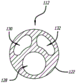
As shown, RICC 102 is a three-lumen RICC comprising a set of three lumens; however, RICC 102 is not limited to the set of three lumens described above. The three lumen set includes a primary lumen 128, a secondary lumen 130, and a third lumen 132 formed by the fluid connection portions of three catheter tube lumens, three catheter hub lumens, and three extension leg lumens. Main lumen 128 has a main lumen orifice 134 in the distal end of first section 120 of catheter tube 112 that corresponds to the distal end of catheter tube 112 and the distal end of RICC 102. The secondary lumen 130 has a secondary lumen orifice 136 on one side of the distal portion of the catheter tube 112. The third lumen 132 has a third lumen orifice 138 on a side of the distal portion of the catheter tube 112 proximal to the second lumen orifice 136.
Fig. 2-6 illustrate various views of a coupler assembly 140 according to some embodiments.
As shown, coupler assembly 140 is a sub-assembly of rich insert assembly 100. In effect, the coupler assembly 140 includes the introducer needle 104 and the coupler 108 coupled together.
Fig. 8-13 illustrate various views of the introducer needle 104 or a component thereof in accordance with some embodiments. Fig. 2-6 illustrate the introducer needle 104 as part of the coupler assembly 140 according to some embodiments.
As shown, the introducer needle 104 includes a needle shaft 142, a sheath 144 over the needle shaft 142, and a needle hub 146 over a proximal portion of the needle shaft 142 and a proximal portion of the sheath 144. At least in the immediate deployment state of the RICC insert assembly 100, the needle shaft 142 and sheath 144 extend from the needle hub 146, through the valve module 176, and out the distal end of the coupler housing 174.
The needle tip 148 includes a bevel 152 having a tip bevel and a primary bevel proximal to the tip bevel. Although not shown, the tip bevel angle of the tip bevel is greater than the main bevel angle of the main bevel such that bevel 152 provides a smooth transition over needle tip 148. Thus, such a needle tip is configured for establishing a needle tract from a skin area of a patient into a lumen of a blood vessel according to a needle tract establishing step of the method described below.
Needle slot 150 extends from a proximal portion of needle shaft 142 through needle tip 148 to form a needle passage 154 along a majority of the length of needle shaft 142 opposite the needle lumen therethrough. The needle slot 150 has a width sized according to the outer diameter of the access guidewire 106 that allows the access guidewire 106 to pass from the proximal portion of the needle shaft 142 through the needle tip 148 when performing the introducer needle withdrawal step of the method described below.
While the needle shaft 142 includes a needle slot 150, it should be understood that the introducer needle 104 includes a needle lumen 156; however, the needle lumen 156 is created by the combination of the needle shaft 142 and the sheath 144 over the needle shaft 142. In effect, the sheath 144 over the needle shaft 142 seals the needle slot 150 therebelow, forming the needle lumen 156 of the introducer needle 104, and enables the syringe 110 to aspirate blood according to the blood aspiration step of the method described below.
The sheath 144 includes a sheath tip 158 in a distal portion of the sheath 144 and a sheath opening 160 in one side of a proximal portion of the sheath 144.
The sheath 144, or the sheath body thereof, is formed of a polymeric material configured to facilitate smooth, consistent insertion of the introducer needle 104 from a patient's skin area into a vascular lumen in accordance with the track establishment procedure of the method described below. In addition, the polymeric material has mechanical properties at the thickness of the sheath 144 that are sufficient to prevent the sheath 144 from collapsing into the needle groove 150 of the needle shaft 142 when performing the blood aspiration step of the method described below, while also facilitating removal of the sheath 144 from the needle shaft 142 according to the introducer needle withdrawal step of the method described below. Such polymeric materials may include, but are not limited to, polyethylene, polypropylene, or polytetrafluoroethylene.
The needle hub 146 includes a needle hub clamp 162 and a needle hub connector 164 in a proximal portion of the needle hub 146. However, it should be understood that other securing means for securing the needle hub 146 to the coupler housing 174 are possible. For example, one or more removable pins passing through the needle hub 146 and the coupler housing 174, one or more removable bands surrounding the needle hub 146 and the coupler housing 174, one or more buttons, one or more lever arms, locking threads, a rotating collar, or a needle housing clamp engaging the needle hub 146 may be used as a securing means for securing the needle hub 146 to the coupler housing 174.
The needle hub connector 164 includes a needle hub bore 171 and an optional needle hub flange 172 surrounding the needle hub bore 171.
The needle hub bore 171 of the needle hub connector 164 is configured to receive a syringe tip (not shown) of the syringe 110 therein for fluidly connecting the introducer needle 104 to the syringe 110. (see fluidly connected introducer needle 104 and syringe 110 in fig. 1.) in practice, needle hub bore 171 may have a luer taper (e.g., 6% taper) configured to receive a syringe tip therein, which may be complementarily configured to have a luer taper.
When present, the needle hub flange 172 surrounding the needle hub bore 171 is configured to screw together with the internal threads of the threaded collar surrounding the syringe tip of the syringe 110. While the threaded collar of the syringe 110 is also optional, when both are present, the needle hub flange 172 advantageously provides a so-called luer lock type connection with the internal threads of the threaded collar. This provides greater safety than that provided by the additional luer slip connection, preventing accidental disconnection of the introducer needle 104 and the syringe 110.
Fig. 6 illustrates a longitudinal cross-section of the coupler 108 according to some embodiments. Fig. 2-6 illustrate a coupler 108 as part of a coupler assembly 140 according to some embodiments.
As shown, the coupler 108 includes a coupler housing 174, a valve module 176 disposed in the coupler housing 174, and an extension arm 178 connected to the coupler housing 174.
The coupler housing 174 includes two molded pieces coupled together (e.g., coupled together with compression pins or hot melt pins, fastened or screwed together with screws or bolts, welded together with ultrasonic welding or hot plate welding, etc.) to form a bullet-shaped body configured to be held comfortably under the hand (e.g., a bracket) by the RICC insert assembly 100 when left-handed venipuncture is performed with the left hand or right-handed venipuncture is performed with the right hand. The interior of each of the two molded pieces includes a recess that forms a valve module compartment 180 and a needle hub receiver 182 when the two molded pieces are coupled together as shown. (see fig. 6 and 7, which include a valve module 176 disposed in a valve module compartment 180 in the distal portion of the coupler housing 174. Fig. 6 also includes a distal portion of the needle hub 146 of the introducer needle 104 inserted or disposed in a needle hub receiver 182 in the proximal portion of the coupler housing 174, as at least in the immediate deployment state of the RICC insert assembly 100.) the exterior of each of the two molded pieces may also include a recess, such as a thumb recess 184 and a finger recess 186, configured to rest at least the RICC insert assembly 100 or its coupler assembly 140. The coupler housing 174 may also include a coupler housing slot 188 that extends partially into the thumb depression 184.
Beginning with the coupler housing slot 188, the coupler housing slot 188 is formed in one of the two molded pieces that does not include the extension arm 178 connected thereto. Thus, the coupler housing slot 188 is located in a side of the coupler housing 174 that does not include the extension arm 178, such as a side of the coupler housing 174 opposite the extension arm 178. The coupler housing groove 188 opens in the same direction as the needle groove 150 of the needle shaft 142, thereby configuring the coupler housing groove 188 to allow the access guidewire 106 to disengage from the coupler housing 174 when the introducer needle 104 is withdrawn from the coupler 108 in an introducer needle withdrawal step of the method described below.
Although described above, it should be appreciated that the coupler housing slot 188 may alternatively be positioned in another location than shown in, for example, fig. 3 and described above. For example, the coupler housing slots 188 may alternatively be positioned opposite or orthogonal to those shown in fig. 3 and described above.
Note that thumb depression 184, thumb depression 184 is located on one side of coupler housing 174 that includes coupler housing groove 188. In effect, coupler housing groove 188 extends partially into thumb recess 184 such that, at least in the immediately deployed state of ric insertion assembly 100, the distal portion of access guidewire 106 extends into thumb recess 184. The thumb depression 184 is configured for thumb pressing the access guidewire 106 into the thumb depression 184 to hold the access guidewire 106 in place at least during percutaneous penetration with the introducer needle 104 or withdrawal of the introducer needle 104 from the coupler 108 through the needle hub 146. Advantageously, the surface of the thumb depression 184 may be textured, e.g., with ridges, bumps, or conversely with dimples as shown in fig. 3, which facilitates holding the access guidewire 106 in place, even in environments where stray fluids may make it difficult to hold the access guidewire 106 in place.
As for the finger recess 186, the finger recess 186 is located on the opposite side of the coupler housing 174 from the thumb recess 184. The finger recess 186 is configured for holding the rich insert assembly 100 or its coupler assembly 140 in the finger while the thumb is resting in the thumb recess 184 or the entry guide wire 106 is pressed into the thumb recess 184 with the thumb at least during percutaneous penetration with the introducer needle 104 or withdrawal of the introducer needle 104 from the coupler 108 through the needle hub 146. Although not shown, the surface of the finger recess 186 may be textured, e.g., with ridges, bumps, or dimples, which may facilitate the resting of the RICC insert assembly 100 or the coupler assembly 140 thereof, even in environments where stray fluids may make such resting difficult.
Although described above, it should be understood that thumb depression 184 and finger depression 186 may alternatively be located in other locations than, for example, those shown in FIG. 2 and described above. For example, thumb recess 184 and finger recess 186 may alternatively be positioned orthogonal to those shown in fig. 2 and described above, thereby providing handedness to RICC insert assembly 100 or coupler assembly 140 thereof, depending on how thumb recess 184 and finger recess 186 are distributed between the sides of coupler housing 174. Notably, the handedness of the rich insert assembly 100 or its coupler assembly 140 also depends on how the clinician chooses to hold such a rich insert assembly or coupler assembly. In one embodiment, a left-handed clinician may find that the rich insert assembly 100 having the thumb recess 184 on the left-hand side of the coupler housing 174 and the finger recess 186 on the right-hand side of the coupler housing 174 is suitable for left-hand venipuncture while holding the rich insert assembly 100 palm-up (underhand). However, right-handed clinicians may find that the aforementioned RICC insert assembly 100 is suitable for right-handed venipuncture while maintaining the RICC insert assembly 100 in a palm-down (coverage) orientation. In another embodiment, a right-handed clinician may find that the rich insert assembly 100 having a thumb recess 184 on the right hand side of the coupler housing 174 and a finger recess 186 on the left hand side of the coupler housing 174 is suitable for right hand venipuncture while holding the rich insert assembly 100 palm up. However, a left-handed clinician may find that the aforementioned rich insert assembly 100 is suitable for left-handed venipuncture while holding the rich insert assembly 100 palm-down.
Note the needle hub receiver 182, the needle hub receiver 182 being configured to retain the needle hub 146 of the introducer needle 104 therein. In effect, needle hub receiver 182 includes needle hub 146 inserted therein at least in the immediately deployed state of ric insertion assembly 100 or coupler assembly 140 thereof. Notably, the needle hub clamp 162 is configured to lock the needle hub 146 in the needle hub receiver 182. The needle hub clamp 162 is also configured to unlock the needle hub 146 when, for example, the pair of clamp arms 166 are pressed toward the needle hub 146 to withdraw the introducer needle 104 from the coupler 108 in an introducer needle withdrawal step of the method described below.
Finally, the valve module compartment 180 is configured to retain the valve module 176 therein. (referring again to fig. 6 and 7, which include a valve module 176 disposed in a valve module compartment 180 in the distal portion of the coupler housing 174.) notably, the valve module compartment 180 is also configured with sufficient space to allow the valve module 176 to separate so as to disengage the access guidewire 106 therefrom when the introducer needle 104 is withdrawn from the coupler 108 in an introducer needle withdrawal step of the method described below.
The valve module 176 includes an access guidewire tube 190 and an integrated blade 192.
The access guidewire channel 190 is configured to guide the access guidewire 106 from the coupler housing groove 188 of the coupler housing 174 into the sheath opening 160 of the sheath 144 and the needle passage 154 of the needle shaft 142 or the needle lumen 156 of the introducer needle 104. In effect, the access guidewire tube 190 includes an access guidewire 106 disposed therein at least in an immediate deployment state of the RICC insertion assembly 100. Notably, at least in the immediate deployment state of the RICC insertion assembly 100, the valve module 176 seals around the proximal portion of the sheath 144 and the distal portion of the access guidewire 106 extending through the sheath opening 160, thereby enabling leak-free aspiration through the introducer needle 104 in accordance with the blood aspiration step of the method described below.
The blade 192 extends from the attachment point in the valve module 176 into the needle slot 150 of the needle shaft 142 such that the blade 192 is disposed in the needle slot 150 below the distal end of the sheath opening 160 of the sheath 144. The blade 192 includes a distally facing blade edge configured to cut the sheath 144 from the needle shaft 142 when the introducer needle 104 is withdrawn from the coupler 108 in a proximal direction through the needle hub 146 in an introducer needle withdrawal step of the method described below. Cutting sheath 144 away from needle shaft 142 allows access guidewire 106 to be disengaged from needle shaft 142 through its needle slot 150 and from coupler 108 through coupler housing slot 188 of coupler housing 174.
The extension arm 178 may be molded in one of two molded pieces of the coupler housing 174 that does not include the coupler housing slot 188, such that the extension arm 178 is integral therewith. Alternatively, the extension arm 178 is molded separately and connected to the molded piece of the coupler housing 174 that does not include the coupler housing slot 188. Regardless, the extension arm 178 is fixedly and preferably immovably connected to a side of the coupler housing 174 that does not include the coupler housing slot 188, such as a side of the coupler housing 174 opposite the coupler housing slot 188. Whereas extension arm 178 is part of the opposite side of coupler housing 174 from coupler housing slot 188, ric insert assembly 100 or coupler assembly 140 thereof advantageously has an immediately identifiable orientation.
FIG. 1 illustrates an access guidewire 106 as part of a RICC insert assembly 100 according to some embodiments.
The access guidewire 106 includes a proximal portion including a proximal end and a distal portion including a distal end. At least in the immediate deployment state of the RICC insert assembly 100, the proximal end of the access guidewire 106 is attached to the extension arm 178, particularly the guidewire attachment point 198 of the extension arm 178. In effect, a proximal portion of access guidewire 106 extends from guidewire attachment point 198 of extension arm 178, through the center of extension arm clamp 194, into the luer connector, and along main lumen 128 of RICC 102. In the immediate deployment state of the rich insertion assembly 100, the distal portion of the access guidewire 106 also extends along the main lumen 128 of the rich 102, but the distal portion of the access guidewire 106 further extends from the distal end of the rich 102, into the valve module 176 through the coupler housing slot 188, into the needle shaft 142 through the sheath opening 160 of the sheath 144 and the needle slot 150 of the needle shaft 142, and along the needle channel 154 of the needle shaft 142 or the needle lumen 156 of the introducer needle 104. As suggested in fig. 1, at least in the immediate deployment state of the RICC insertion assembly 100, the distal end of the access guidewire 106 is disposed in the needle lumen 156 of the introducer needle 104, just proximal of the needle tip 148. Again, at least in the immediate deployment state of the rich insertion assembly 100, the proximal and distal ends of the access guidewire 106 implement a loop in the access guidewire 106 over which the rich 102 is disposed, thereby maintaining the rich insertion assembly 100 in a relatively compact form.
The access guidewire 106 may include a guidewire tip 200 in a distal portion of the access guidewire 106 that takes on a "J" shape configured to prevent puncture of the vessel's back wall. Such a guidewire tip assumes a straightened state, at least in an immediate deployed state of the rich insertion assembly 100, and a curved state when the guidewire tip 200 is advanced beyond the needle tip 148 (e.g., into a vessel lumen) in the deployed state of the rich insertion assembly 100.
The access guidewire 106 may also include a bare wire portion and a coiled portion proximal to the bare wire portion. Although not shown, the bare wire portion, when present, extends distally through the access guidewire tubing 190 of the valve module 176 at least in the immediate deployment state of the ric insert assembly 100 such that the valve module 176 forms a fluid-tight seal around the bare wire portion of the access guidewire 106. Notably, the aforementioned bare wire portion may alternatively be a flat wound or ground wound portion into the guidewire 106, wherein the flat wound portion comprises windings of a ribbon rather than windings of a round wire, and wherein the ground wound portion comprises windings of a round wire ground to flatten the windings.
Method
Methods include methods for inserting ric 102 into a vascular lumen of a patient. The method includes one or more steps selected from a rich insertion assembly obtaining step, a needle track establishing step, a blood aspiration step, an entering guidewire advancing step, a clamp opening step, an entering guidewire securing step, an entering guidewire visualization step, an introducer needle withdrawing step, a rich advancing step, a rich decoupling step, an entering guidewire withdrawing step, an operating guidewire advancing step, another rich advancing step, and an operating guidewire withdrawing step.
The insert component obtaining step includes obtaining a RICC insert component 100. As described above, RICC insert assembly 100 includes RICC 102, introducer needle 104 including sheath 144 over needle shaft 142, and access guidewire 106 coupled together by coupler 108. The proximal end of the access guidewire 106 is coupled to an extension arm 178 of the coupler 108. The distal end of the access guidewire 106 is disposed in the introducer needle 104 through the valve module 176 of the coupler 108. Proximal and distal ends of access guidewire 106 implement a loop in access guidewire 106 over which ric 102 is disposed at least in an immediate deployment state of ric insertion assembly 100. In the immediate deployment state of the ric insert assembly 100, the ric 102 disposed over the ring maintains the ric insert assembly 100 in a relatively compact form.
The needle track establishing step includes establishing a needle track from the skin area to the lumen of the blood vessel with the introducer needle 104. The needle track establishing step may further comprise ensuring blood flashback while establishing the needle track. Ensuring blood flashback while establishing a needle path includes ensuring blood flashback into the needle hub 146 of the introducer needle 104, particularly when the needle hub 146 is transparent and colorless, the syringe tip of the syringe 110 is fluidly connected to the introducer needle 104, the barrel of the syringe 110, or a combination thereof. While the needle tract is being established, a slight vacuum may be drawn with the syringe 110 such that blood flows back at least into the needle hub 146 of the introducer needle 104 while the needle tract is being established. Ensuring blood flashback confirms that the needle tract extends into the lumen of the blood vessel as previously described.
The blood aspiration step includes aspirating blood with the syringe 110 coupled to the needle hub 146 to confirm that the needle tract extends into the vessel lumen, particularly prior to withdrawing the introducer needle 104 from the coupler 108 in the introducer needle withdrawal step. Likewise, the sheath 144 above the needle shaft 142 seals the needle slot 150 of the needle shaft 142 below it. In particular, the sheath 144 seals the needle slot 150 outside of the valve module 176. Valve module 176 in turn seals over sheath opening 160 of sheath 144, which sheath opening 160 allows access to guidewire 106 through needle slot 150 into needle shaft 142 in the immediate deployment state of rich insertion assembly 100. The valve module 176 also seals around the distal portion of the access guidewire 106. This seal enables the syringe 110 to aspirate blood during the blood aspiration step.
The entry guidewire advancing step includes advancing the distal end of entry guidewire 106 into the vessel lumen from its initial position in needle shaft 142 (just proximal of needle tip 148 of needle shaft 142) to thereby secure vascular access for rich 102 during the rich advancing step.
The clip opening step includes, for example, pressing the pair of clip arms 166 toward the centerline of the needle hub 146 of the introducer needle 104. Pressing the pair of clip arms 166 toward the needle hub 146 disengages the coupler housing 174 of the coupler 108 from which each clip arm 166 of the pair of clip arms 166 extends to subsequently perform the introducer needle withdrawal step.
The access guidewire securing step includes pressing the access guidewire 106 with a thumb into the thumb depression 184 on the side of the coupler housing 174 that includes the coupler housing groove 188. Pressing the access guidewire 106 into the thumb depression 184 may hold the access guidewire 106 in place during the needle track establishment step or the introducer needle withdrawal step.
The access guidewire visualization step includes visualizing the access guidewire 106 in the extension arm opening 196. As described above, the extension arm opening 196 passes through opposite sides of the extension arm 178 between the proximal end of the extension arm 178 and the connection portion of the extension arm 178 that connects the extension arm 178 to the remainder of the coupler housing 174. Visualization of the access guidewire 106 is to confirm that the access guidewire 106 is attached to the guidewire attachment point 198 of the extension arm 178.
The introducer needle withdrawal step includes withdrawing the introducer needle 104 from the coupler 108 through the needle hub 146, leaving the access guidewire 106 in place in the lumen of the blood vessel. The introducer needle withdrawal step includes simultaneously resecting the sheath 144 from the needle shaft 142 as the introducer needle 104 is withdrawn from the coupler 108, with the blades 192 of the valve module 176 disposed in the valve module compartment 180 of the coupler housing 174. The removal of the sheath 144 from the needle shaft 142 allows the access guidewire 106 to be disengaged from the needle shaft 142 through its needle slot 150. Again, the introducer needle 104 includes a needle slot 150 extending from the proximal portion of the needle shaft 142 through the needle tip 148, which allows the access guidewire 106 to be disengaged from the introducer needle 104 while the sheath 144 is resected from the needle shaft 142. Notably, as the introducer needle 104 is withdrawn from the coupler 108 during the introducer needle withdrawal step, the valve module 176 and sheath 144 around the needle shaft 142 separate to allow the entry guide wire 106 to be further disengaged from the valve module 176. In addition, the coupler housing 174 includes a coupler housing slot 188 located on the opposite side of the coupler housing 174 from the extension arm 178, the coupler housing slot 188 opening in the same direction as the needle slot 150 of the needle shaft 142. The coupler housing groove 188 is configured to allow the access guidewire 106 to be further disengaged from the coupler housing 174 when the introducer needle 104 is withdrawn from the coupler 108 during the introducer needle withdrawal step.
The rich advancement step includes advancing catheter tube 112 of rich 102 over access guidewire 106 and into the vessel lumen, thereby inserting rich 102 into the vessel lumen.
The rich decoupling step includes removing the luer connector of rich 102 from extension arm clamp 194 of extension arm 178 during the rich advancing step, thereby decoupling rich 102 from coupler 108 during the remainder of the rich advancing step. Notably, the coupler 108 or its extension arm 178 becomes the handle for accessing the guidewire 106.
The access guidewire withdrawal step includes withdrawing the access guidewire 106, leaving the catheter tubing 112 in place in the lumen of the vessel.
The steering guidewire advancing step includes advancing the steering guidewire through main lumen 128 of rich 102 into the vessel lumen and into the lower 1/3 of the SVC of the patient's heart.
Another rich advancement step includes advancing the distal portion of catheter tube 112 further into the vessel lumen to the lower 1/3 of the SVC of the patient's heart by manipulating the guidewire.
The steering guidewire withdrawal step includes withdrawing the steering guidewire, leaving the catheter tubing 112 in place in the lower 1/3 of the SVC.
Although certain embodiments have been disclosed herein, and although specific embodiments have been disclosed in considerable detail, these specific embodiments are not intended to limit the scope of the concepts provided herein. Additional adaptations and/or modifications will occur to those skilled in the art and are, in a broader aspect, contemplated. Accordingly, changes may be made to the specific embodiments disclosed herein without departing from the scope of the concepts provided herein.
Claims (28)
1. A quick-insertion type center catheter insertion assembly, comprising:
a center catheter that can be inserted quickly;
an introducer needle, the introducer needle comprising:
a needle shaft including a longitudinal needle slot extending from a proximal portion of the needle shaft through a distal needle tip;
a sheath located over the needle shaft, sealing the needle slot therebelow except below a sheath opening in a proximal portion of the sheath; and
a needle hub located over a proximal portion of the needle shaft and a proximal portion of the sheath;
an access guidewire, the access guidewire comprising:
a proximal portion including a proximal end; and
a distal portion comprising a distal end disposed in the introducer needle just proximal of the needle tip at least in an immediate deployment state of the quick-insertable central catheter insertion assembly; and
a coupler coupling the quick-insertable central catheter, the introducer needle, and the access guidewire together, the coupler comprising:
a coupler housing, at least in an immediate deployment state of the quick-insertable central catheter insertion assembly, a securing means for securing the needle hub to the coupler housing secures the needle hub to the coupler housing; and
An extension arm connected to the coupler housing, a proximal end of the access guidewire being attached to the extension arm, the proximal and distal ends of the access guidewire implementing a loop in the access guidewire, the quick-insertable central catheter being disposed over the loop at least in an immediate deployment state of the quick-insertable central catheter insertion assembly.
2. The quick-insertable center catheter insertion assembly according to claim 1, wherein the securing means for securing the needle hub to the coupler housing is a needle hub clip that clips onto the coupler housing at least in an immediate deployment state of the quick-insertable center catheter insertion assembly.
3. The quick connect type center catheter hub assembly of claim 2 wherein said needle hub clamp is integral with said needle hub.
4. The quick-insertion center catheter insertion assembly of claim 2, wherein the needle hub clamp comprises a single lever clamp arm extending distally above the needle hub from a fulcrum connecting the clamp arm to a remainder of the needle hub, the clamp arm including a protrusion extending from a distal portion thereof, the protrusion configured to engage a recess in a corresponding side of a coupler housing when the clamp arm is clamped on the coupler housing and disengage from the recess when a proximal portion of the clamp arm is pressed toward a centerline of the needle hub.
5. The quick-insertion center catheter insertion assembly of claim 2, wherein the needle hub clamp includes a pair of lever clamp arms extending distally over opposite sides of the needle hub from corresponding pairs of fulcrums connecting the clamp arms to the remainder of the needle hub, each clamp arm of the pair of clamp arms including a protrusion extending from a distal portion thereof, the protrusion configured to engage with a recess in a corresponding side of the coupler housing to clamp the needle hub on the coupler housing and disengage from the recess when a proximal portion of the clamp arm is pressed toward a centerline of the needle hub.
6. The quick-insertion center catheter insertion assembly of claim 2, wherein the coupler housing comprises a longitudinal coupler housing slot in a side of the coupler housing opposite the extension arm, the coupler housing slot opening in the same direction as a needle slot of the needle shaft, the coupler housing slot configured to allow the access guidewire to disengage from the coupler housing during withdrawal of the introducer needle from the coupler through the needle hub.
7. The quick-insertion center catheter insertion assembly of claim 6, wherein the coupler housing comprises a thumb depression in a side of the coupler housing comprising the coupler housing slot, the thumb depression configured to thumb the access guidewire therein to hold the access guidewire in place at least during percutaneous penetration using the introducer needle or withdrawal of the introducer needle from the coupler through the needle hub.
8. The quick-insertable central catheter insertion assembly according to claim 7, wherein the coupler housing slot extends partially into the thumb depression such that a distal portion of the access guidewire extends into the thumb depression at least in an immediate deployment state of the quick-insertable central catheter insertion assembly.
9. The quick connect type center catheterization assembly of claim 7, wherein the thumb concave surface is textured.
10. The quick-insertion center catheter insertion assembly of claim 7, wherein the coupler housing includes a finger recess in a side of the coupler housing opposite the thumb recess, the finger recess configured to finger rest the quick-insertion center catheter insertion assembly while the access guidewire is pressed into the thumb recess with the thumb at least during percutaneous penetration with the introducer needle or withdrawal of the introducer needle from the coupler through the needle hub.
11. The quick connect type center catheter hub assembly of claim 2 wherein said extension arm is integral with said coupler housing.
12. The rapid-insertion central catheter insertion assembly of claim 2, wherein at least in an immediate deployment state of the rapid-insertion central catheter insertion assembly, the extension arm terminates in the extension arm clip that clamps onto a luer connector of the rapid-insertion central catheter, a proximal portion of the access guidewire extends from the luer connector, through a center of the extension arm clip, and to a guidewire attachment point of the extension arm to which the proximal end of the access guidewire is attached.
13. The quick-connect hub catheter insertion assembly of claim 12, wherein the extension arm clamp comprises a socket into which a proximal end of the luer connector of the quick-connect hub catheter is inserted when the extension arm clamp is clamped onto the luer connector.
14. The quick-insertion center catheter insertion assembly of claim 12, wherein the extension arm includes an extension arm opening through opposite sides of the extension arm between the extension arm clamp and a connection portion of the extension arm that connects the extension arm to a remainder of the coupler housing, the extension arm opening configured to provide a window through which the access guidewire is visualized to confirm that the access guidewire is attached to a guidewire attachment point of the extension arm.
15. The quick-insertable central catheter insertion assembly according to claim 2, wherein the coupler housing comprises a needle hub receiver in a proximal portion of the coupler housing, a distal portion of the needle hub being inserted into the needle hub receiver at least in an immediate deployment state of the quick-insertable central catheter insertion assembly.
16. The quick-insertion center catheter insertion assembly of claim 2, wherein the coupler further comprises a valve module disposed in a valve module compartment of the coupler housing, the valve module sealing around a proximal portion of the sheath and a distal portion of the access guidewire extending through the sheath opening at least in an immediate deployment state of the quick-insertion center catheter insertion assembly, thereby enabling leak-free aspiration through the introducer needle.
17. The quick-insertion center catheter insertion assembly of claim 16, wherein the valve module comprises an integrated blade disposed in the needle slot below a distal end of the sheath opening, the blade comprising a distally-facing blade edge configured to sever the sheath from the needle shaft during withdrawal of the introducer needle from the coupler through the needle hub, thereby allowing the access guidewire to disengage from the needle shaft via the needle slot of the needle shaft.
18. The quick-insertable center catheterization assembly of claim 2, further comprising a syringe fluidly coupled to the introducer needle at least in an immediate deployment state of the quick-insertable center catheterization assembly.
19. A coupler assembly for a quick-insertion type center catheter insertion assembly, comprising:
an introducer needle, the introducer needle comprising:
a needle shaft including a longitudinal needle slot extending from a proximal portion of the needle shaft through a distal needle tip;
a sheath located over the needle shaft, sealing the needle slot therebelow except below a sheath opening in a proximal portion of the sheath; and
a needle hub located over the proximal portion of the needle shaft and the proximal portion of the sheath, the needle hub comprising a needle hub clamp; and
a coupler coupled with the introducer needle, the coupler comprising:
a coupler housing on which the needle hub clamp is clamped, at least in an immediate deployment state of the coupler assembly; and
an extension arm connected to the coupler housing, the extension arm configured for attaching a proximal end of an access guidewire thereto.
20. The coupler assembly of claim 19, wherein the needle hub clamp includes a pair of lever clamp arms extending distally over opposite sides of the needle hub from corresponding pairs of fulcrums connecting the clamp arms to the remainder of the needle hub, each clamp arm of the pair of clamp arms including a protrusion extending from a distal portion thereof, the protrusion configured to engage a recess in the corresponding side of the coupler housing to clamp the needle hub on the coupler housing and disengage from the recess when a proximal portion of the clamp arm is pressed toward a centerline of the needle hub.
21. The coupler assembly of claim 19, wherein the coupler housing includes a longitudinal coupler housing slot in a side of the coupler housing opposite the extension arm that opens in the same direction as the needle slot of the needle shaft, the coupler housing slot configured to allow the access guidewire to disengage from the coupler housing when the access guidewire is disposed therein.
22. The coupler assembly of claim 21, wherein the coupler housing includes a thumb depression in a side of the coupler housing including the coupler housing slot such that the coupler housing slot extends partially into the thumb depression, the thumb depression configured for thumb-pressing the access guidewire therein to hold the access guidewire in place when the access guidewire is disposed in the coupler housing.
23. The coupler assembly of claim 22, wherein the coupler housing includes a finger recess in a side of the coupler housing opposite the thumb recess, the finger recess configured to finger rest the coupler assembly while pressing the access guidewire into the thumb recess with the thumb when the access guidewire is disposed in the coupler housing.
24. The coupler assembly of claim 19, wherein the extension arm terminates in an extension arm clamp configured as a socket into which a proximal end of a luer connector of a quick-insertion center catheter is inserted to clamp the extension arm clamp onto the luer connector.
25. The coupler assembly of claim 24, wherein the extension arm includes an extension arm opening through opposite sides of the extension arm between the extension arm clamp and a connection portion of the extension arm that connects the extension arm to a remainder of the coupler housing, the extension arm opening configured to provide a window through which the access guidewire is visualized to confirm that the access guidewire is attached to the guidewire attachment point of the extension arm when the access guidewire is attached to the guidewire attachment point.
26. The coupler assembly of claim 19, wherein the coupler housing includes a needle hub receiver in a proximal portion of the coupler housing, a distal portion of the needle hub being inserted into the needle hub receiver at least in an immediate deployment state of the quick-insertable central catheter insertion assembly.
27. The coupler assembly of claim 19, wherein the coupler further comprises a valve module disposed in a valve module compartment of the coupler housing, the valve module sealing around a proximal portion of the sheath and the access guidewire when the access guidewire extends through the sheath opening, thereby enabling leak-free aspiration through the introducer needle.
28. The coupler assembly of claim 27, wherein the valve module includes an integrated blade disposed in the needle slot below a distal end of the sheath opening, the blade including a distally facing blade edge configured to cut the sheath from the needle shaft during withdrawal of the introducer needle from the coupler through the needle hub.
Applications Claiming Priority (6)
| Application Number | Priority Date | Filing Date | Title |
|---|---|---|---|
| US202163249009P | 2021-09-27 | 2021-09-27 | |
| US63/249,009 | 2021-09-27 | ||
| US202163271043P | 2021-10-22 | 2021-10-22 | |
| US63/271,043 | 2021-10-22 | ||
| US202263318945P | 2022-03-11 | 2022-03-11 | |
| US63/318,945 | 2022-03-11 |
Publications (1)
| Publication Number | Publication Date |
|---|---|
| CN219167451U true CN219167451U (en) | 2023-06-13 |
Family
ID=83899810
Family Applications (2)
| Application Number | Title | Priority Date | Filing Date |
|---|---|---|---|
| CN202211182277.1A Pending CN115845227A (en) | 2021-09-27 | 2022-09-27 | Quick-pluggable central catheter insertion assembly and coupler assembly therefor |
| CN202222569224.7U Active CN219167451U (en) | 2021-09-27 | 2022-09-27 | Quick-insertable center catheter insertion assembly and coupler assembly therefor |
Family Applications Before (1)
| Application Number | Title | Priority Date | Filing Date |
|---|---|---|---|
| CN202211182277.1A Pending CN115845227A (en) | 2021-09-27 | 2022-09-27 | Quick-pluggable central catheter insertion assembly and coupler assembly therefor |
Country Status (5)
| Country | Link |
|---|---|
| US (1) | US20230102231A1 (en) |
| EP (1) | EP4405025A1 (en) |
| JP (1) | JP2024535398A (en) |
| CN (2) | CN115845227A (en) |
| WO (1) | WO2023049519A1 (en) |
Families Citing this family (10)
| Publication number | Priority date | Publication date | Assignee | Title |
|---|---|---|---|---|
| WO2016123278A1 (en) | 2015-01-29 | 2016-08-04 | Redsmith, Inc. | Rapid insertion integrated catheter and method of using an integrated catheter |
| US11826526B2 (en) | 2020-01-23 | 2023-11-28 | Bard Access Systems, Inc. | Splitable catheter docking station system and method |
| WO2021216902A1 (en) | 2020-04-23 | 2021-10-28 | Bard Access Systems, Inc. | Rapidly insertable central catheters including catheter assemblies |
| CA3181532A1 (en) | 2020-05-21 | 2021-11-25 | Bard Access Systems, Inc. | Rapidly insertable central catheters including catheter assemblies |
| WO2022005892A2 (en) | 2020-06-29 | 2022-01-06 | Bard Access Systems, Inc. | Rapidly insertable central catheters including catheter assemblies and methods thereof |
| CA3186461A1 (en) | 2020-06-29 | 2022-01-06 | Bard Access Systems, Inc. | Rapidly insertable central catheters including assemblies |
| EP4232130A1 (en) | 2020-10-28 | 2023-08-30 | Bard Access Systems, Inc. | Catheter placement system with stiffening system |
| AU2021400331B2 (en) | 2020-12-17 | 2025-09-25 | Bard Access Systems, Inc. | Rapidly insertable central catheters and assemblies |
| JP2024500227A (en) | 2020-12-21 | 2024-01-05 | バード・アクセス・システムズ,インコーポレーテッド | Optimized structural support in catheter insertion systems |
| EP4259256A1 (en) | 2020-12-21 | 2023-10-18 | Bard Access Systems, Inc. | Fluid path optimization in catheter insertion systems |
Family Cites Families (12)
| Publication number | Priority date | Publication date | Assignee | Title |
|---|---|---|---|---|
| US5380290A (en) * | 1992-04-16 | 1995-01-10 | Pfizer Hospital Products Group, Inc. | Body access device |
| US6726659B1 (en) * | 1999-12-09 | 2004-04-27 | John E. Stocking | Catheter assembly having a fenestrated dilator |
| US8029481B2 (en) * | 2006-10-17 | 2011-10-04 | Matthew Dickson Reavill | Apparatus and method of inserting an infusing catheter and determining catheter depth without a guidewire or direct contact with the catheter |
| US20090187147A1 (en) * | 2008-01-22 | 2009-07-23 | Pressure Products Medical Supplies, Inc. | Apparatus and method for achieving micropuncture |
| WO2009114833A1 (en) * | 2008-03-14 | 2009-09-17 | Access Scientific, Inc. | Access device |
| US20100305474A1 (en) * | 2009-05-27 | 2010-12-02 | Cook Critical Care Incorporated | Apparatus for dispensing a wire guide |
| CA2799360C (en) * | 2010-05-14 | 2018-11-20 | C.R. Bard, Inc. | Catheter placement device and method |
| US9950139B2 (en) * | 2010-05-14 | 2018-04-24 | C. R. Bard, Inc. | Catheter placement device including guidewire and catheter control elements |
| US20140081210A1 (en) * | 2011-05-25 | 2014-03-20 | Access Scientific, Llc | Access device |
| WO2015054621A1 (en) * | 2013-10-11 | 2015-04-16 | The Trustees Of Columbia University In The City Of New York | Right angle cannula probe for coronary sinus cannulation |
| EP3417902B1 (en) * | 2016-02-18 | 2024-05-01 | Terumo Kabushiki Kaisha | Catheter assembly |
| AU2020353080B2 (en) * | 2019-09-24 | 2025-10-09 | Bard Access Systems, Inc. | An integrated acute central venous catheter and peripherally inserted venous catheter |
-
2022
- 2022-09-27 JP JP2024518733A patent/JP2024535398A/en active Pending
- 2022-09-27 WO PCT/US2022/044918 patent/WO2023049519A1/en not_active Ceased
- 2022-09-27 EP EP22793038.5A patent/EP4405025A1/en active Pending
- 2022-09-27 CN CN202211182277.1A patent/CN115845227A/en active Pending
- 2022-09-27 CN CN202222569224.7U patent/CN219167451U/en active Active
- 2022-09-27 US US17/954,096 patent/US20230102231A1/en active Pending
Also Published As
| Publication number | Publication date |
|---|---|
| WO2023049519A1 (en) | 2023-03-30 |
| EP4405025A1 (en) | 2024-07-31 |
| JP2024535398A (en) | 2024-09-30 |
| CN115845227A (en) | 2023-03-28 |
| US20230102231A1 (en) | 2023-03-30 |
Similar Documents
| Publication | Publication Date | Title |
|---|---|---|
| CN219167451U (en) | Quick-insertable center catheter insertion assembly and coupler assembly therefor | |
| CN219090754U (en) | Quick insertable center catheter insertion assembly and introducer needle assembly | |
| CN219595553U (en) | Quick-insertable central catheterization assembly | |
| CN219090755U (en) | Quick-insertion type central catheter insertion assembly | |
| CN215916116U (en) | Quick-insertion central catheter assembly | |
| CN219090734U (en) | Quick insertable central catheter insertion assembly and introducer needle | |
| CN113926046B (en) | A centrally inserted conduit including components and its method | |
| CN219251197U (en) | Quick-insertion type central catheter insertion assembly | |
| US6905481B2 (en) | Percutaneous catheter assembly | |
| EP1819390B1 (en) | Introducer apparatus | |
| US20070049960A1 (en) | Method of implanting a multi-lumen catheter | |
| US20080082056A1 (en) | Introducer assembly and method therefor | |
| CN221155038U (en) | Quick-insertable central catheter insertion assembly, valve module therefor, and introducer assembly | |
| CN222218403U (en) | Quick insertable center catheter insertion assembly and introducer needle subassembly | |
| CN219783466U (en) | Introducer needle |
Legal Events
| Date | Code | Title | Description |
|---|---|---|---|
| GR01 | Patent grant | ||
| GR01 | Patent grant |