CN218298703U - Light bar assembly, backlight module and display device - Google Patents
Light bar assembly, backlight module and display device Download PDFInfo
- Publication number
- CN218298703U CN218298703U CN202220907664.6U CN202220907664U CN218298703U CN 218298703 U CN218298703 U CN 218298703U CN 202220907664 U CN202220907664 U CN 202220907664U CN 218298703 U CN218298703 U CN 218298703U
- Authority
- CN
- China
- Prior art keywords
- light
- emitting unit
- sub
- different
- bar assembly
- Prior art date
- Legal status (The legal status is an assumption and is not a legal conclusion. Google has not performed a legal analysis and makes no representation as to the accuracy of the status listed.)
- Active
Links
Images


Classifications
-
- G—PHYSICS
- G02—OPTICS
- G02F—OPTICAL DEVICES OR ARRANGEMENTS FOR THE CONTROL OF LIGHT BY MODIFICATION OF THE OPTICAL PROPERTIES OF THE MEDIA OF THE ELEMENTS INVOLVED THEREIN; NON-LINEAR OPTICS; FREQUENCY-CHANGING OF LIGHT; OPTICAL LOGIC ELEMENTS; OPTICAL ANALOGUE/DIGITAL CONVERTERS
- G02F1/00—Devices or arrangements for the control of the intensity, colour, phase, polarisation or direction of light arriving from an independent light source, e.g. switching, gating or modulating; Non-linear optics
- G02F1/01—Devices or arrangements for the control of the intensity, colour, phase, polarisation or direction of light arriving from an independent light source, e.g. switching, gating or modulating; Non-linear optics for the control of the intensity, phase, polarisation or colour
- G02F1/13—Devices or arrangements for the control of the intensity, colour, phase, polarisation or direction of light arriving from an independent light source, e.g. switching, gating or modulating; Non-linear optics for the control of the intensity, phase, polarisation or colour based on liquid crystals, e.g. single liquid crystal display cells
- G02F1/133—Constructional arrangements; Operation of liquid crystal cells; Circuit arrangements
- G02F1/1333—Constructional arrangements; Manufacturing methods
- G02F1/1335—Structural association of cells with optical devices, e.g. polarisers or reflectors
- G02F1/1336—Illuminating devices
- G02F1/133602—Direct backlight
- G02F1/133603—Direct backlight with LEDs
-
- F—MECHANICAL ENGINEERING; LIGHTING; HEATING; WEAPONS; BLASTING
- F21—LIGHTING
- F21S—NON-PORTABLE LIGHTING DEVICES; SYSTEMS THEREOF; VEHICLE LIGHTING DEVICES SPECIALLY ADAPTED FOR VEHICLE EXTERIORS
- F21S4/00—Lighting devices or systems using a string or strip of light sources
- F21S4/20—Lighting devices or systems using a string or strip of light sources with light sources held by or within elongate supports
-
- F—MECHANICAL ENGINEERING; LIGHTING; HEATING; WEAPONS; BLASTING
- F21—LIGHTING
- F21V—FUNCTIONAL FEATURES OR DETAILS OF LIGHTING DEVICES OR SYSTEMS THEREOF; STRUCTURAL COMBINATIONS OF LIGHTING DEVICES WITH OTHER ARTICLES, NOT OTHERWISE PROVIDED FOR
- F21V23/00—Arrangement of electric circuit elements in or on lighting devices
- F21V23/003—Arrangement of electric circuit elements in or on lighting devices the elements being electronics drivers or controllers for operating the light source, e.g. for a LED array
- F21V23/004—Arrangement of electric circuit elements in or on lighting devices the elements being electronics drivers or controllers for operating the light source, e.g. for a LED array arranged on a substrate, e.g. a printed circuit board
- F21V23/005—Arrangement of electric circuit elements in or on lighting devices the elements being electronics drivers or controllers for operating the light source, e.g. for a LED array arranged on a substrate, e.g. a printed circuit board the substrate is supporting also the light source
-
- G—PHYSICS
- G02—OPTICS
- G02F—OPTICAL DEVICES OR ARRANGEMENTS FOR THE CONTROL OF LIGHT BY MODIFICATION OF THE OPTICAL PROPERTIES OF THE MEDIA OF THE ELEMENTS INVOLVED THEREIN; NON-LINEAR OPTICS; FREQUENCY-CHANGING OF LIGHT; OPTICAL LOGIC ELEMENTS; OPTICAL ANALOGUE/DIGITAL CONVERTERS
- G02F1/00—Devices or arrangements for the control of the intensity, colour, phase, polarisation or direction of light arriving from an independent light source, e.g. switching, gating or modulating; Non-linear optics
- G02F1/01—Devices or arrangements for the control of the intensity, colour, phase, polarisation or direction of light arriving from an independent light source, e.g. switching, gating or modulating; Non-linear optics for the control of the intensity, phase, polarisation or colour
- G02F1/13—Devices or arrangements for the control of the intensity, colour, phase, polarisation or direction of light arriving from an independent light source, e.g. switching, gating or modulating; Non-linear optics for the control of the intensity, phase, polarisation or colour based on liquid crystals, e.g. single liquid crystal display cells
- G02F1/133—Constructional arrangements; Operation of liquid crystal cells; Circuit arrangements
- G02F1/1333—Constructional arrangements; Manufacturing methods
- G02F1/1335—Structural association of cells with optical devices, e.g. polarisers or reflectors
- G02F1/1336—Illuminating devices
- G02F1/133602—Direct backlight
- G02F1/133608—Direct backlight including particular frames or supporting means
-
- F—MECHANICAL ENGINEERING; LIGHTING; HEATING; WEAPONS; BLASTING
- F21—LIGHTING
- F21Y—INDEXING SCHEME ASSOCIATED WITH SUBCLASSES F21K, F21L, F21S and F21V, RELATING TO THE FORM OR THE KIND OF THE LIGHT SOURCES OR OF THE COLOUR OF THE LIGHT EMITTED
- F21Y2103/00—Elongate light sources, e.g. fluorescent tubes
- F21Y2103/10—Elongate light sources, e.g. fluorescent tubes comprising a linear array of point-like light-generating elements
-
- F—MECHANICAL ENGINEERING; LIGHTING; HEATING; WEAPONS; BLASTING
- F21—LIGHTING
- F21Y—INDEXING SCHEME ASSOCIATED WITH SUBCLASSES F21K, F21L, F21S and F21V, RELATING TO THE FORM OR THE KIND OF THE LIGHT SOURCES OR OF THE COLOUR OF THE LIGHT EMITTED
- F21Y2113/00—Combination of light sources
- F21Y2113/10—Combination of light sources of different colours
- F21Y2113/13—Combination of light sources of different colours comprising an assembly of point-like light sources
- F21Y2113/17—Combination of light sources of different colours comprising an assembly of point-like light sources forming a single encapsulated light source
-
- F—MECHANICAL ENGINEERING; LIGHTING; HEATING; WEAPONS; BLASTING
- F21—LIGHTING
- F21Y—INDEXING SCHEME ASSOCIATED WITH SUBCLASSES F21K, F21L, F21S and F21V, RELATING TO THE FORM OR THE KIND OF THE LIGHT SOURCES OR OF THE COLOUR OF THE LIGHT EMITTED
- F21Y2115/00—Light-generating elements of semiconductor light sources
- F21Y2115/10—Light-emitting diodes [LED]
Landscapes
- Physics & Mathematics (AREA)
- Nonlinear Science (AREA)
- Crystallography & Structural Chemistry (AREA)
- Mathematical Physics (AREA)
- Chemical & Material Sciences (AREA)
- General Physics & Mathematics (AREA)
- Optics & Photonics (AREA)
- Engineering & Computer Science (AREA)
- General Engineering & Computer Science (AREA)
- Microelectronics & Electronic Packaging (AREA)
- Planar Illumination Modules (AREA)
- Circuit Arrangement For Electric Light Sources In General (AREA)
- Non-Portable Lighting Devices Or Systems Thereof (AREA)
Abstract
本公开是关于一种灯条组件、背光模组及显示装置,灯条组件包括灯板,灯板上设置多种发出不同波长的光的发光单元阵列,由控制电路板上的两个连接器分别控制不同发光单元阵列的发光单元的点亮比例,使得灯条组件以渐变方式调整不同发光单元阵列各自的辐照比例,模拟一整天的节律照明参数,使得包括该灯条组件的显示装置满足节律效应,从而实现健康显示的效果。
The disclosure relates to a light bar assembly, a backlight module and a display device. The light bar assembly includes a light board, and the light board is provided with a variety of light-emitting unit arrays emitting light of different wavelengths, controlled by two connectors on the circuit board. The lighting ratios of the light-emitting units of different light-emitting unit arrays are respectively controlled, so that the light bar assembly adjusts the respective irradiance ratios of different light-emitting unit arrays in a gradual manner, simulating the rhythmic lighting parameters of the whole day, so that the display device including the light bar assembly Satisfy the rhythm effect, so as to achieve the effect of health display.
Description
技术领域technical field
本公开涉及显示技术领域,具体而言,涉及一种灯条组件、背光模组显示装置。The present disclosure relates to the field of display technology, in particular, to a light bar assembly and a backlight module display device.
背景技术Background technique
节律照明参数是一种具有多种功能的光信号,通过其分泌的改变,将环境光周期的信息传递给体内有关的组织和器官,使它们的功能活动适应外界的变化。Rhythmic lighting parameter is a kind of light signal with multiple functions. Through the change of its secretion, the information of environmental photoperiod is transmitted to relevant tissues and organs in the body, so that their functional activities can adapt to the changes of the outside world.
光波长对节律照明参数有一定影响,现有显示装置在输出到用户人眼的光谱比例是恒定的,无法适应人体生物节律效应,实现健康显示的效果。The wavelength of light has a certain influence on the rhythmic lighting parameters. The spectral ratio output to the user's eyes by the existing display device is constant, which cannot adapt to the biological rhythm effect of the human body and achieve the effect of healthy display.
需要说明的是,在上述背景技术部分公开的信息仅用于加强对本公开的背景的理解,因此可以包括不构成对本领域普通技术人员已知的现有技术的信息。It should be noted that the information disclosed in the above background section is only for enhancing the understanding of the background of the present disclosure, and therefore may include information that does not constitute the prior art known to those of ordinary skill in the art.
实用新型内容Utility model content
本公开的目的在于控制灯条组件输出到人眼的光谱比例,提供一种灯条组件、背光模组及显示装置。The purpose of the present disclosure is to control the spectral ratio output from the light bar assembly to human eyes, and to provide a light bar assembly, a backlight module and a display device.
根据本公开的一个方面,提供一种灯条组件,包括灯板和控制电路板,灯板上设有至少两种不同的发光单元阵列,每种发光单元阵列包括多个发光单元,不同种发光单元用于发出不同波长的光,每种发光单元阵列的多个发光单元的走线集成于一出线端;控制电路板上设有至少两个连接器,不同连接器一一对应地连接于不同种发光单元阵列的出线端,以控制不同种发光单元阵列的发光单元的点亮比例。According to one aspect of the present disclosure, there is provided a light bar assembly, including a light board and a control circuit board. At least two different light emitting unit arrays are provided on the light board, and each light emitting unit array includes a plurality of light emitting units. The unit is used to emit light of different wavelengths. The wiring of multiple light-emitting units of each light-emitting unit array is integrated at one outlet; there are at least two connectors on the control circuit board, and different connectors are connected to different different types of light-emitting unit arrays to control the lighting ratio of the light-emitting units of different kinds of light-emitting unit arrays.
在本公开的一个实施例中,不同种发光单元阵列沿第一方向设于灯板的一侧,相邻两种不同发光单元阵列中,一种发光单元阵列的发光单元位于另一种发光单元阵列的发光单元之间。In one embodiment of the present disclosure, different types of light-emitting unit arrays are arranged on one side of the lamp panel along the first direction, and among two adjacent different light-emitting unit arrays, the light-emitting units of one type of light-emitting unit array are located in the other type of light-emitting unit between the light-emitting units of the array.
在本公开的一个实施例中,相互之间距离最近的不同种发光单元组成一发光单元组,发光单元组设为多晶单独封装LED、多晶非单独封装 LED或多个单晶LED。In one embodiment of the present disclosure, the different kinds of light-emitting units closest to each other form a light-emitting unit group, and the light-emitting unit group is set as polycrystalline individually packaged LEDs, polycrystalline non-individually packaged LEDs, or multiple single-crystalline LEDs.
在本公开的一个实施例中,灯板包括沿第二方向设置的多个子灯板,第二方向垂直于第一方向,多个子灯板相互嵌套,每一子灯板上设置有一组发光单元阵列,相邻两个子灯板的发光单元位于同一平面且沿第一方向排成一列。In one embodiment of the present disclosure, the lamp panel includes a plurality of sub-lamp panels arranged along a second direction, the second direction is perpendicular to the first direction, the plurality of sub-lamp panels are nested with each other, and each sub-lamp panel is provided with a group of light emitting In the unit array, the light-emitting units of two adjacent sub-lamp panels are located on the same plane and arranged in a row along the first direction.
在本公开的一个实施例中,相邻设置的两个子灯板中,一个子灯板的一侧沿第一方向设有多个第一凸起,一个子灯板的发光单元一一对应地设于不同的第一凸起上,相邻两个第一凸起之间形成第一凹槽,另一灯板沿其长度方向设有多个第二凸起,另一子灯板的发光单元一一对应地设于第二凸起上,多个第一凸起一一对应地设于第一凹槽内。In one embodiment of the present disclosure, among the two sub-lamp panels arranged adjacently, one side of one sub-lamp panel is provided with a plurality of first protrusions along the first direction, and the light-emitting units of one sub-lamp panel correspond to each other one by one. It is arranged on different first protrusions, a first groove is formed between two adjacent first protrusions, and the other lamp board is provided with a plurality of second protrusions along its length direction, and the light emission of the other sub-lamp board The units are arranged on the second protrusions in one-to-one correspondence, and the first protrusions are arranged in the first grooves in one-to-one correspondence.
在本公开的一个实施例中,不同发光单元阵列的出线端沿第一方向位于灯板的不同位置。In one embodiment of the present disclosure, the wire outlets of different light emitting unit arrays are located at different positions of the light panel along the first direction.
在本公开的一个实施例中,灯板设有两种不同的发光单元阵列,其中第一种发光单元阵列发出波长为470-480纳米的光,第二种发光单元阵列发出415-455纳米的光,控制电路板控制第一发光单元阵列的发光单元的点亮比例随着时间的增长不断减小,控制电路板控制第二发光单元阵列的发光单元的点亮比例随着时间的增长不断增大。In one embodiment of the present disclosure, the light panel is provided with two different light-emitting unit arrays, wherein the first light-emitting unit array emits light with a wavelength of 470-480 nanometers, and the second light-emitting unit array emits light with a wavelength of 415-455 nanometers. Light, the control circuit board controls the lighting ratio of the light-emitting units of the first light-emitting unit array to decrease with time, and the control circuit board controls the lighting ratio of the light-emitting units of the second light-emitting unit array to increase with time Big.
在本公开的一个实施例中,第一时刻时,第一种发光单元阵列的发光单元的点亮比例为95%,第二种发光单元阵列的发光单元的点亮比例为5%;第二时刻时,第一种发光单元阵列的发光单元的点亮比例为50%,第二种发光单元阵列的发光单元的点亮比例为50%,第二时刻晚于第一时刻。In one embodiment of the present disclosure, at the first moment, the lighting ratio of the light-emitting units of the first type of light-emitting unit array is 95%, and the lighting ratio of the light-emitting units of the second type of light-emitting unit array is 5%; the second At time, the lighting ratio of the light-emitting units of the first type of light-emitting unit array is 50%, and the lighting ratio of the light-emitting units of the second type of light-emitting unit array is 50%, and the second time is later than the first time.
在本公开的一个实施例中,第三时刻时,第一种发光单元阵列的发光单元的点亮比例为5%,第二种发光单元阵列的发光单元的点亮比例为 95%,第三时刻晚于第二时刻。In an embodiment of the present disclosure, at the third moment, the lighting ratio of the light-emitting units of the first type of light-emitting unit array is 5%, the lighting ratio of the light-emitting units of the second type of light-emitting unit array is 95%, and the lighting ratio of the third type of light-emitting unit array is 95%. The time is later than the second time.
根据本公开的另一个方面,提供一种背光模组,包括本公开的一个方面所述的灯条组件。According to another aspect of the present disclosure, a backlight module is provided, including the light bar assembly described in one aspect of the present disclosure.
根据本公开的另一个方面,提供一种组装治具,用于组装本公开另一个方面所述的灯条组件,组装治具包括治具本体、至少两种安装槽和至少两种不同的滑块,安装槽用于设置子灯板,相邻两种不同的安装槽相互嵌套,且沿第二方向设置于治具本体的不同位置;不同滑块用于与不同子灯板可拆卸连接,滑块设于对应安装槽的一侧,且能够沿第二方向滑动。According to another aspect of the present disclosure, there is provided an assembly jig for assembling the light bar assembly described in another aspect of the present disclosure, the assembly jig includes a jig body, at least two types of mounting grooves and at least two different sliding Block, the installation groove is used to set the sub-light board, and two different adjacent installation grooves are nested with each other, and are arranged at different positions of the fixture body along the second direction; different sliders are used for detachable connection with different sub-light boards , the slider is arranged on one side corresponding to the installation groove, and can slide along the second direction.
在本公开的一个实施例中,相邻两种不同的安装槽沿第三方向设于治具本体的不同位置,第三方向垂直于第一方向和第二方向。In one embodiment of the present disclosure, two different adjacent mounting grooves are provided at different positions of the jig body along a third direction, and the third direction is perpendicular to the first direction and the second direction.
本公开的灯条组件包括灯板,灯板上设置多种发出不同波长的光的发光单元阵列,由控制电路板上的两个连接器分别控制不同发光单元阵列的发光单元的点亮比例,使得灯条组件以渐变方式调整不同发光单元阵列各自的辐照比例,模拟一整天的节律照明参数,使得包括该灯条组件的显示装置满足节律效应,从而实现健康显示的效果。The light bar assembly of the present disclosure includes a light board, on which a variety of light-emitting unit arrays emitting light of different wavelengths are arranged, and the lighting ratios of the light-emitting units of different light-emitting unit arrays are respectively controlled by two connectors on the control circuit board. The light bar assembly adjusts the respective irradiance ratios of different light-emitting unit arrays in a gradual manner, simulating rhythmic lighting parameters throughout the day, so that the display device including the light bar assembly satisfies the rhythm effect, thereby achieving a healthy display effect.
应当理解的是,以上的一般描述和后文的细节描述仅是示例性和解释性的,并不能限制本公开。It is to be understood that both the foregoing general description and the following detailed description are exemplary and explanatory only and are not restrictive of the present disclosure.
附图说明Description of drawings
此处的附图被并入说明书中并构成本说明书的一部分,示出了符合本公开的实施例,并与说明书一起用于解释本公开的原理。显而易见地,下面描述中的附图仅仅是本公开的一些实施例,对于本领域普通技术人员来讲,在不付出创造性劳动的前提下,还可以根据这些附图获得其他的附图。The accompanying drawings, which are incorporated in and constitute a part of this specification, illustrate embodiments consistent with the disclosure and together with the description serve to explain the principles of the disclosure. Apparently, the drawings in the following description are only some embodiments of the present disclosure, and those skilled in the art can obtain other drawings according to these drawings without creative efforts.
图1为相关技术中灯条组件的结构示意图。FIG. 1 is a schematic structural diagram of a light bar assembly in the related art.
图2为本公开实施例涉及的一种灯条组件的结构示意图。Fig. 2 is a schematic structural diagram of a light bar assembly according to an embodiment of the present disclosure.
图3为图2中A部位的局部放大图。Fig. 3 is a partially enlarged view of part A in Fig. 2 .
图4为本公开实施例涉及的一种发光单元组的结构示意图。Fig. 4 is a schematic structural diagram of a light emitting unit group according to an embodiment of the present disclosure.
图5为本公开实施例涉及的另一种发光单元组的结构示意图。FIG. 5 is a schematic structural diagram of another light emitting unit group involved in an embodiment of the present disclosure.
图6为本公开实施例涉及的又一种发光单元组的结构示意图。FIG. 6 is a schematic structural diagram of another light-emitting unit group involved in an embodiment of the present disclosure.
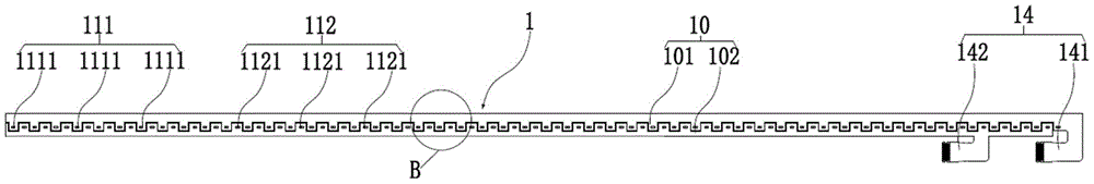
图7为本公开实施例涉及的另一种灯条组件的结构示意图。Fig. 7 is a schematic structural diagram of another light bar assembly according to an embodiment of the present disclosure.
图8为图7中B部位的局部放大图。FIG. 8 is a partially enlarged view of part B in FIG. 7 .
图9为本公开实施例涉及的第一子灯板与固定胶带贴合的结构示意图。Fig. 9 is a schematic structural diagram of the bonding of the first sub-lamp board and the fixing tape according to the embodiment of the present disclosure.
图10为本公开实施例涉及的灯板组件与组装治具的配合图。Fig. 10 is a cooperation diagram of the lamp panel assembly and the assembly jig according to the embodiment of the present disclosure.
图11为本公开实施例涉及的灯板组件与显示背板安装的示意图。FIG. 11 is a schematic diagram of installation of a light panel assembly and a display backplane according to an embodiment of the present disclosure.
图12为本公开实施例涉及的组装治具与灯板组件拆卸的示意图。FIG. 12 is a schematic diagram of disassembly of the assembly jig and the lamp panel assembly according to the embodiment of the present disclosure.
图13为本公开实施例涉及的显示面板的结构示意图。FIG. 13 is a schematic structural diagram of a display panel according to an embodiment of the present disclosure.
图中:1-灯条组件,10-灯板,101-第一子灯板,1011-第一凸起,102- 第二子灯板,1021-第二凸起,11-发光单元阵列,110-发光单元,111-第一种发光单元阵列,1111-第一发光单元,112-第二种发光单元阵列,1121- 第二发光单元,13-发光单元组,14-出线端,141-第一出线端,142-第二出线端,2-组装治具,21-治具本体,211-第一安装槽,2111-第一卡接部, 212-第二安装槽,2121-第二卡接部,213-第一滑块,214-第二滑块,3- 固定胶带。In the figure: 1-light bar assembly, 10-light board, 101-first sub-light board, 1011-first protrusion, 102-second sub-light board, 1021-second protrusion, 11-light-emitting unit array, 110-light-emitting unit, 111-first light-emitting unit array, 1111-first light-emitting unit, 112-second light-emitting unit array, 1121-second light-emitting unit, 13-light-emitting unit group, 14-outlet terminal, 141- First outlet, 142-second outlet, 2-assembly fixture, 21-fixture body, 211-first installation slot, 2111-first clamping part, 212-second installation slot, 2121-second Clamping part, 213-first slider, 214-second slider, 3-fixing tape.
具体实施方式detailed description
现在将参考附图更全面地描述示例实施方式。然而,示例实施方式能够以多种形式实施,且不应被理解为限于在此阐述的实施方式;相反,提供这些实施方式使得本公开将全面和完整,并将示例实施方式的构思全面地传达给本领域的技术人员。图中相同的附图标记表示相同或类似的结构,因而将省略它们的详细描述。此外,附图仅为本公开的示意性图解,并非一定是按比例绘制。Example embodiments will now be described more fully with reference to the accompanying drawings. Example embodiments may, however, be embodied in many forms and should not be construed as limited to the embodiments set forth herein; rather, these embodiments are provided so that this disclosure will be thorough and complete, and will fully convey the concept of example embodiments to those skilled in the art. The same reference numerals in the drawings denote the same or similar structures, and thus their detailed descriptions will be omitted. Furthermore, the drawings are merely schematic illustrations of the present disclosure and are not necessarily drawn to scale.
虽然本说明书中使用相对性的用语,例如“上”“下”来描述图标的一个组件对于另一组件的相对关系,但是这些术语用于本说明书中仅出于方便,例如根据附图中所述的示例的方向。能理解的是,如果将图标的装置翻转使其上下颠倒,则所叙述在“上”的组件将会成为在“下”的组件。当某结构在其它结构“上”时,有可能是指某结构一体形成于其它结构上,或指某结构“直接”设置在其它结构上,或指某结构通过另一结构“间接”设置在其它结构上。Although relative terms such as "upper" and "lower" are used in this specification to describe the relative relationship of one component of an icon to another component, these terms are used in this specification only for convenience, for example, according to the description in the accompanying drawings directions for the example described above. It will be appreciated that if the illustrated device is turned over so that it is upside down, then elements described as being "upper" will become elements that are "lower". When a structure is "on" another structure, it may mean that a structure is integrally formed on another structure, or that a structure is "directly" placed on another structure, or that a structure is "indirectly" placed on another structure through another structure. other structures.
用语“一个”、“一”、“该”、“所述”和“至少一个”用以表示存在一个或多个要素/组成部分/等;用语“包括”和“具有”用以表示开放式的包括在内的意思并且是指除了列出的要素/组成部分/等之外还可存在另外的要素/组成部分/等;用语“第一”、“第二”和“第三”等仅作为标记使用,不是对其对象的数量限制。The terms "a", "an", "the", "said" and "at least one" are used to indicate the presence of one or more elements/components/etc; the terms "comprising" and "have" are used to indicate an open and means that there may be additional elements/components/etc. in addition to the listed elements/components/etc.; the terms "first", "second" and "third" etc. only Used as a marker, not a limit on the number of its objects.
在光谱质量方面,提出通过调整光谱来支持人类健康,进一步提出了照明要支持警醒、睡眠和健康的生理节律功能。通过照明来支持每日生理节律,以满足不同应用场合对性能和健康的特定需求,例如:工作环境、康复中心、教育设施等。In terms of spectral quality, it is proposed to support human health by adjusting the spectrum, and it is further proposed that lighting should support wakefulness, sleep and healthy circadian rhythm functions. Supporting daily circadian rhythms through lighting to meet the specific needs of performance and health in different applications such as: working environments, rehabilitation centers, educational facilities, etc.
CRHD(Circadian Rhythm Health Display,生理节律调节健康显示),是首次提出的一种健康显示功能,旨在利用人体节律效应,通过调节显示装置不同发光状态,从而使人体处于“睡眠”或“清醒”的环境,达到健康使用显示装置的效果。CRHD (Circadian Rhythm Health Display, Circadian Rhythm Health Display), is a health display function proposed for the first time, which aims to make the human body "sleep" or "awake" by adjusting the different lighting states of the display device by using the rhythm effect of the human body environment, to achieve the effect of healthy use of the display device.
光照周期是生命活动最主要的物理环境,昼夜光暗信号将体内众多的固有的生理节律移到其自身周期上来。一般来说,光照昼夜周期与动物生命所需的信号有一定关系。通常能影响生理节律的照明产品的光的波长位于460~520nm。The light cycle is the most important physical environment for life activities, and the light and dark signals of day and night move many inherent circadian rhythms in the body to its own cycle. In general, the circadian cycle of light is related to the signals required for animal life. Generally, the wavelength of light of lighting products that can affect circadian rhythm is located at 460-520nm.
以褪黑素为例进行说明。褪黑素作为节律照明参数的一种,褪黑素分泌的昼夜节律周期机制是内源性的,是人在漫长的进化中形成的,早已印刻到基因之中。Take melatonin as an example. Melatonin is one of the rhythmic lighting parameters. The circadian rhythm cycle mechanism of melatonin secretion is endogenous, formed in the long evolution of human beings, and has already been imprinted into the gene.
褪黑素(melatonin)是一种具有多种功能的光信号,通过其分泌的改变,将环境光周期的信息传递给体内有关的组织和器官,使它们的功能活动适应外界的变化。它在调节昼夜节律、季节节律以及人体睡眠等觉醒节律方面有非常重要的作用。Melatonin is a kind of light signal with multiple functions. Through the change of its secretion, it transmits the information of environmental photoperiod to relevant tissues and organs in the body, so that their functional activities can adapt to the changes of the outside world. It plays a very important role in regulating circadian rhythms, seasonal rhythms, and wakefulness rhythms such as human sleep.
短波蓝光是波长处于400nm-480nm之间,具有相对较高能量的光线,该波长内的蓝光会使眼睛内的黄斑区毒素量增高,严重威胁我们的眼底健康,并且蓝光会诱发盲眼病。Short-wave blue light is light with a wavelength between 400nm-480nm and relatively high energy. Blue light in this wavelength will increase the amount of toxins in the macular area of the eye, seriously threatening the health of our fundus, and blue light can induce blindness.
人的眼睛里有30000个感光细胞可以接收到某一波长范围内的光,并将它们识别为蓝光,这些光照射到特定的细胞,细胞向大脑的视交叉上核区域发出一个信号,并告诉大脑关闭褪黑素的分泌,而褪黑素就是睡眠的启动器。There are 30,000 photoreceptor cells in the human eye that can receive light in a certain wavelength range and recognize them as blue light. The light hits specific cells, which send a signal to the suprachiasmatic nucleus area of the brain and tell The brain shuts down the production of melatonin, the trigger for sleep.
光波长对褪黑素合成抑制作用的大小顺序排列依次为蓝光>绿光>黄光>紫外光>红光,抑制效果最大时对应的峰值波长为470-480nm的蓝光。The order of the inhibitory effect of light wavelengths on melatonin synthesis is blue light>green light>yellow light>ultraviolet light>red light, and the peak wavelength corresponding to blue light at 470-480nm is the maximum inhibitory effect.
如图1所示,相关技术中,灯条组件1上的走线为一整套,发光单元阵列11的所有发光单元110通过串并联方式集成为一处出线端14,由控制电路板的一个连接器统一控制。因此,显示装置输出到用户人眼的光谱比例是恒定的。而在夜间,过多比例的蓝光(470-480nm波长的光尤为明显)会引起体内褪黑素分泌被抑制,使用户睡眠质量变差,长期会引起亚健康状态。As shown in Figure 1, in the related art, the wiring on the
基于此,本公开实施方式提供了一种灯条组件。该灯条组件包括灯板和控制电路板(图中未示出),灯板上设有至少两种不同的发光单元阵列,每种发光单元阵列包括多个发光单元,不同种发光单元用于发出不同波长的光,每种发光单元阵列的多个发光单元的走线集成于一出线端;控制电路板上设有至少两个连接器,不同连接器一一对应地连接于不同种发光单元阵列的出线端,以控制不同种发光单元阵列的发光单元的点亮比例。Based on this, embodiments of the present disclosure provide a light bar assembly. The light bar assembly includes a light board and a control circuit board (not shown in the figure), and at least two different light-emitting unit arrays are arranged on the light board, and each light-emitting unit array includes a plurality of light-emitting units, and different kinds of light-emitting units are used for Light of different wavelengths is emitted, and the wiring of multiple light-emitting units of each light-emitting unit array is integrated at one outlet; at least two connectors are provided on the control circuit board, and different connectors are connected to different light-emitting units in one-to-one correspondence The outlet terminal of the array is used to control the lighting ratio of the light-emitting units of the different types of light-emitting unit arrays.
设置多种发出不同波长的光的发光单元阵列,由控制电路板上的两个连接器分别控制不同发光单元阵列的发光单元的点亮比例,使得灯条组件以渐变方式调整不同发光单元阵列各自的辐照比例,模拟一整天的节律照明参数,使得包括该灯条组件的显示装置满足节律效应。A variety of light-emitting unit arrays that emit light of different wavelengths are set, and the lighting ratios of the light-emitting units of different light-emitting unit arrays are controlled by two connectors on the control circuit board, so that the light bar assembly adjusts the respective light-emitting unit arrays in a gradual manner. The irradiance ratio simulates the rhythmic lighting parameters throughout the day, so that the display device including the light bar assembly satisfies the rhythmic effect.
灯条组件包括灯板,灯板上设有至少两种不同的发光单元阵列,每种发光单元阵列包括多个发光单元,不同种发光单元用于发出不同波长的光。每种发光单元阵列的多个发光单元的走线集成于一出线端。The light bar assembly includes a light board. At least two different light emitting unit arrays are arranged on the light board. Each light emitting unit array includes a plurality of light emitting units. Different kinds of light emitting units are used to emit light of different wavelengths. The wires of multiple light-emitting units of each light-emitting unit array are integrated at one outlet.
根据节律照明参数的模拟需求,灯板上可以设置包括但不限于两种不同的发光单元阵列、三种不同的发光单元阵列或者四种不同的发光单元阵列。需要说明的是,这里仅仅是对发光单元阵列数量的一种列举,并不进行限定,还可以在灯板上设置更多种不同的发光单元阵列。According to the simulation requirements of the rhythmic lighting parameters, the lamp board may be provided with, but not limited to, two different light-emitting unit arrays, three different light-emitting unit arrays or four different light-emitting unit arrays. It should be noted that this is only an enumeration of the number of light-emitting unit arrays, and it is not limited, and more kinds of different light-emitting unit arrays can also be arranged on the lamp board.
不同种发光单元阵列沿第一方向设于灯板的一面,相邻两个发光单元阵列可以相互平行,即不同发光单元阵列的单个发光单元在第二方向设于同一直线,第二方向垂直于第一方向。相邻两种不同发光单元阵列也可以交错设置,即不同发光单元阵列的发光单元沿第一方向位于同一直线。需要说明的是,第一方向指的是灯板的长度方向。Different kinds of light-emitting unit arrays are arranged on one side of the lamp panel along the first direction, and two adjacent light-emitting unit arrays can be parallel to each other, that is, the single light-emitting units of different light-emitting unit arrays are arranged on the same line in the second direction, and the second direction is perpendicular to first direction. Two different adjacent light-emitting unit arrays can also be arranged alternately, that is, the light-emitting units of different light-emitting unit arrays are located on the same straight line along the first direction. It should be noted that the first direction refers to the length direction of the lamp panel.
无论相邻两种不同发光单元阵列的发光单元是沿第一方向位于同一直线还是沿第二方向位于同一直线,相互之间距离最近的不同种发光单元组成一发光单元组。Regardless of whether the light-emitting units of two adjacent different light-emitting unit arrays are located on the same line along the first direction or on the same line along the second direction, the different types of light-emitting units with the closest distance to each other form a light-emitting unit group.
如图2和图3所示,灯条组件1包括灯板10,灯板10上设有两种不同的发光单元阵列,两种不同发光单元阵列的发光单元沿第一方向位于同一直线。第一种发光单元阵列111包括多个第一发光单元1111,第二种发光单元阵列112包括多个第二发光单元1121,第一发光单元1111 和第二发光单元1121分别发出不同波长的光,第一发光单元1111位于相邻两个第二发光单元1121之间,第二单元位于相邻两个第一发光单元 1111之间。第一发光单元1111与第二发光单元1121组成一发光单元组 13。As shown in FIG. 2 and FIG. 3 , the
发光单元组13可以设为如图4所示的多晶单独封装LED,也可以设为如图5所示的多晶非单独封装LED,还可以设为如图6所示的多个单晶LED。The light-emitting
可以理解的是,即多个第一发光单元1111和多个第二发光单元1121 沿第一方向位于同一直线,也就是第一种发光单元阵列111与第二种发光单元阵列112交错设置。第一种发光单元阵列111的多个发光单元的走线集成于第一出线端141,第二种发光单元阵列112的多个发光单元的走线集成于第二出线端142。第一种发光单元阵列111、第二种发光单元阵列112和灯板10集成为一个灯条,组装简易,节省人工成本,且组装对位精度较高。It can be understood that the plurality of first light-emitting
灯板可以包括沿第二方向设置的多个子灯板,第二方向垂直于第一方向,多个子灯板相互嵌套,每一子灯板上设置有一组发光单元阵列,多个子灯板的发光单元位于同一平面且沿第一方向排成一列。The lamp panel may include a plurality of sub-lamp panels arranged along the second direction, the second direction is perpendicular to the first direction, the plurality of sub-lamp panels are nested with each other, each sub-lamp panel is provided with a group of light-emitting unit arrays, and the plurality of sub-lamp panels The light emitting units are located on the same plane and arranged in a row along the first direction.
根据节律照明参数的模拟需求,可以设置包括但不限于两个子灯板、三个子灯板、四个子灯板,需要说明的是,这里仅仅是对子灯板的数量的一种列举,并不进行限定,还可以在设置更多的子灯板,多个子灯板相互嵌套,每个子灯板上设置一组发光单元阵列,相邻两个子灯板上的发光单元阵列设为不同种。According to the simulation requirements of rhythmic lighting parameters, it can be set including but not limited to two sub-light boards, three sub-light boards, and four sub-light boards. For limitation, it is also possible to set more sub-light boards, multiple sub-light boards are nested with each other, each sub-light board is provided with a set of light-emitting unit arrays, and the light-emitting unit arrays on two adjacent sub-light boards are set to be of different types.
相邻设置的两个子灯板中,一个子灯板的一侧沿第一方向设有多个第一凸起,一个子灯板的发光单元一一对应地设于不同的第一凸起上,相邻两个第一凸起之间形成第一凹槽,另一子灯板沿其长度方向设有多个第二凸起,另一子灯板的发光单元一一对应地设于第二凸起上,多个第一凸起一一对应地设于第一凹槽内。Among the two sub-lamp panels arranged adjacently, one side of one sub-lamp panel is provided with a plurality of first protrusions along the first direction, and the light-emitting units of one sub-lamp panel are arranged on different first protrusions in a one-to-one correspondence , a first groove is formed between two adjacent first protrusions, the other sub-lamp board is provided with a plurality of second protrusions along its length direction, and the light-emitting units of the other sub-lamp board are arranged on the first sub-lamp board one by one. On the two protrusions, a plurality of first protrusions are correspondingly arranged in the first groove.
可以理解的是,每相邻两个子灯板的发光单元位于同一平面且沿第一方向排成一列,多个子灯板的发光单元可以在一方向上排成相互平行的多列。It can be understood that the light emitting units of every two adjacent sub-light boards are located on the same plane and arranged in a row along the first direction, and the light-emitting units of multiple sub-light boards can be arranged in multiple parallel rows in one direction.
如图7和图8所示,灯板10包括沿第二方向设置的第一子灯板101 和第二子灯板102,第二方向垂直于第一方向,第一子灯板101与第二子灯板102相互嵌套,第一子灯板101上设置有第一种发光单元阵列111,第二子灯板102上设置有第二种发光单元阵列112。第一种发光单元阵列111包括多个第一发光单元1111,第二发光单元1121阵列包括多个第二发光单元1121,第一发光单元1111设于第一子灯板101的第一凸起 1011上,第二发光单元1121设于第二子灯板102的第二凸起1021上,第二凸起1021位于两个第一凸起1011之间形成的凹槽内。As shown in Figures 7 and 8, the
第二凸起1021位于相邻两个第一凸起1011之间,因此第二发光单元1121位于两个第一发光单元1111之间,第一凸起1011位于相邻两个第二凸起1021之间,因此第一发光单元1111位于两个第二发光单元1121 之间。可以理解的是,第一种发光单元阵列111与第二种发光单元阵列 112沿第一方向交错设置。第一种发光单元阵列111与第一子灯板101 形成第一灯条,第二种发光单元阵列112与第二子灯板102形成第二灯条,第一灯条和第二灯条单独设计及走线,发光单元采用单晶LED,单晶LED封装更加稳定,且针对不良维修可各自操作及替换,节省成本。The second protrusion 1021 is located between two adjacent
需要说明的是,无论采用的是图2示出的灯板组件还是图4示出的灯板组件,不同发光单元阵列的出线端14沿第一方向位于灯板的不同位置。It should be noted that, no matter the lamp panel assembly shown in FIG. 2 or the lamp panel assembly shown in FIG. 4 is used, the
下面结合具体的节律照明参数,以发光组件包括两种发光单元阵列,对第一发光单元的发光波长和第二发光单元的发光波长进行说明。通常第一发光单元发出波长为470-480纳米的光,第二发光单元1121发出415-455纳米的光。The light emitting wavelength of the first light emitting unit and the light emitting wavelength of the second light emitting unit will be described below with reference to the specific rhythmic lighting parameters and assuming that the light emitting component includes two kinds of light emitting unit arrays. Generally, the first light-emitting unit emits light with a wavelength of 470-480 nanometers, and the second light-emitting
控制电路板控制第一发光单元阵列的发光单元的点亮比例随着时间的增长不断减小,控制电路板控制第二发光单元阵列的发光单元的点亮比例随着时间的增长不断增大。The control circuit board controls the lighting ratio of the light-emitting units of the first light-emitting unit array to decrease with time, and the control circuit board controls the lighting ratio of the light-emitting units of the second light-emitting unit array to increase with time.
模拟一整天的生理节律需求,以渐变滚动形式调整第一发光单元阵列和第二发光单元阵列各自的辐照比例,最终体现为灯条组件1发出的光的波长,满足客户终端不同时段节律照明参数的实际需求。Simulate the circadian rhythm requirements throughout the day, adjust the respective irradiance ratios of the first light-emitting unit array and the second light-emitting unit array in the form of gradual scrolling, and finally reflect the wavelength of the light emitted by the
下面对灯条组件的发光模式进行举例说明。The light emitting mode of the light bar assembly is illustrated as an example below.
第一时刻8:00时,第一种发光单元阵列的发光单元的点亮比例为 95%,第二种发光单元阵列的发光单元的点亮比例为5%。第二时刻17:00 时,第一种发光单元阵列的发光单元的点亮比例为50%,第二种发光单元阵列的发光单元的点亮比例为50%,第二时刻晚于第一时刻。第三时刻21:00时,第一种发光单元阵列的发光单元的点亮比例为5%,第二种发光单元阵列的发光单元的点亮比例为95%,第三时刻晚于第二时刻。At 8:00 at the first moment, the lighting ratio of the light emitting units of the first type of light emitting unit array is 95%, and the lighting ratio of the light emitting units of the second type of light emitting unit array is 5%. At 17:00 at the second moment, the lighting ratio of the light-emitting units of the first type of light-emitting unit array is 50%, and the lighting ratio of the light-emitting units of the second type of light-emitting unit array is 50%, and the second moment is later than the first moment . At 21:00 at the third moment, the lighting ratio of the light-emitting units of the first type of light-emitting unit array is 5%, and the lighting ratio of the light-emitting units of the second type of light-emitting unit array is 95%, and the third moment is later than the second moment .
可以理解的是,第一时刻8:00时发出波长为480纳米的光最多,因此对褪黑素的抑制作用最强,在用户处于比较困乏的时段时,该灯条组件1能够影响用户处于较为清醒的状态。第二时刻17:00时发出波长为 480纳米的光和低蓝光各占一半,因此对褪黑素的抑制作用较弱。因为此时用户处于精神状态较好的时段,该灯条组件1同样能够影响用户处于较为清醒的状态。第三时刻21:00时发出的低蓝光较多,因此对褪黑素的抑制作用最弱,此时用户处于准备入睡的时段,该灯条组件1能够减小对睡眠的影响。It can be understood that the light with a wavelength of 480 nanometers is the most emitted at 8:00 at the first moment, so it has the strongest inhibitory effect on melatonin. more awake state. At 17:00 at the second moment, the light with a wavelength of 480 nanometers and the low blue light each account for half, so the inhibitory effect on melatonin is weak. Because the user is in a good state of mind at this time, the
当然,用户也可以根据自身精神状态,手动设置第一种发光单元阵列的发光单元的点亮比例和第二种发光单元阵列的发光单元的点亮比例,以满足用户的个性化需求。Of course, the user can also manually set the lighting ratio of the light-emitting units of the first type of light-emitting unit array and the lighting ratio of the light-emitting units of the second type of light-emitting unit array according to his own mental state, so as to meet the individual needs of the user.
本公开实施方式提供了一种组装治具,用于组装上面的灯条组件。该组装治具包括治具本体、至少两种安装槽和至少两种不同的滑块,至少两种安装槽沿第二方向依次设置于治具本体的一侧,安装槽用于设置子灯板,相邻两种不同的安装槽相互嵌套,且沿第二方向设于治具本体的不同位置;不同滑块用于与不同子灯板可拆卸连接,滑块设于对应安装槽的一侧,且能够沿治具本体的高度方向滑动。The embodiment of the present disclosure provides an assembly jig for assembling the above light bar assembly. The assembly jig includes a jig body, at least two types of installation grooves and at least two different sliders, the at least two types of installation grooves are sequentially arranged on one side of the jig body along the second direction, and the installation grooves are used to set the sub-lamp board , two different adjacent mounting grooves are nested with each other, and are arranged at different positions of the fixture body along the second direction; different sliders are used for detachable connection with different sub-lamp boards, and the sliders are set in one of the corresponding mounting grooves side, and can slide along the height direction of the jig body.
安装槽的形状大小与对应的子灯板的形状大小相匹配,具体可以是相邻两个安装槽,其中一个安装槽包括多个第一卡接部,第一卡接部与第一凸起的形状大小相同,另一个安装槽包括多个第二卡接部,第二卡接部与第二凸起的形状大小相同。相邻两种不同的安装槽可以沿第二方向设于治具本体的不同位置。The shape and size of the installation groove match the shape and size of the corresponding sub-lamp board. Specifically, there may be two adjacent installation grooves, one of which includes a plurality of first clamping parts, and the first clamping part and the first protrusion have the same shape and size, and the other installation groove includes a plurality of second locking parts, and the second locking parts and the second protrusions have the same shape and size. Two different adjacent mounting grooves can be arranged at different positions of the jig body along the second direction.
如图10所示,组装治具2包括治具本体21、第一安装槽211、第二安装槽212、第一滑块213和第二滑块214,第一安装槽211与第二安装槽212相互嵌套,且沿第二方向设于治具本体21的不同位置;第一安装槽211和第二安装槽212沿第二方向依次设置于治具本体21的一侧。As shown in Figure 10, the
需要说明的是,第二方向为治具本体21的高度方向。第一安装槽 211用于设置第一子灯板101,第二安装槽212用于设置第二子灯板102,第二安装槽212的高度高于第一安装槽211的高度,因此治具本体21的高度高于第二安装槽212的高度。It should be noted that the second direction is the height direction of the
第一滑块213设于第一安装槽211的一侧,第一滑块213用于与第一子灯板101可拆卸连接,第二滑块214设于第二安装槽212的一侧,第二滑块214用于与第二子灯板102可拆卸连接。第一滑块213和第二滑块214能够沿第二方向滑动。The
第一子灯板101与第二子灯板102可以是同时滑动的,该情况下可以将第一安装槽211与第二安装槽212沿第三方向设于同一位置。第一子灯板101与第二子灯板102也可以是分别滑动的,该情况下需要将第一安装槽211与第二安装槽212沿第三方向设于不同位置,保证第一子灯板101和第二子灯板102滑动时在第三方向相互错开,不会相互影响。The first
灯条组件的组装步骤如图9至图12所示:The assembly steps of the light bar assembly are shown in Figure 9 to Figure 12:
在第一灯条上的第一种发光单元阵列111的发光面相对的一面贴附固定胶带3,将第二灯条上的第二种发光单元阵列112的发光面相对的一面也贴附于固定胶带3。Attach the fixing
将第一灯条放进组装治具2第一安装槽211,并用第一滑块213固定第一灯条,将第二灯条放进组装治具2第二安装槽212,并用第二滑块214固定第二灯条。Put the first light strip into the
将组装治具2在第二方向上沿W朝向推进U折内部,然后先向上推动第一滑块213,直至第一灯条的第一出线端141从U折上预先设置的破孔伸出,再向上推动第二滑块214,直至第二灯条的第二出线端142 从U折上预先设置的另一破孔伸出。Push the
第一滑块213在第一滑轨内滑动,第二滑块214在第二滑轨内滑动,第一滑轨和第二滑轨均自带定位缺口,可以保证第一灯条和第二灯条的推进位置统一。第一灯条和第二灯条推进到位后,撕下固定胶带3远离第一种发光单元阵列111发光面的一侧的离型纸,使第一灯条和第二灯条贴附于背板上被固定好。The first sliding
将第一滑块213与第一灯条分离,在第二方向上沿S朝向移动第一滑块213脱离第一灯条,将第二滑块214与第二灯条分离,在第二方向上沿S朝向移动第二滑块214脱离第二灯条,然后取出组装治具2。Separate the
本公开实施方式提供了一种显示装置。如图13所示,该显示装置包括显示面板,显示面板可以包括显示背板4和背光模组,背光模组可以包括上面的灯条组件1。显示装置的有益效果可以参考灯条组件的有益效果,在此不再进行赘述。Embodiments of the present disclosure provide a display device. As shown in FIG. 13 , the display device includes a display panel, and the display panel may include a
需要说明的是,该显示装置除了显示面板以外,还包括其他必要的部件和组成,以显示器为例,具体例如外壳、电路板、电源线,等等,本领域技术人员可根据该显示装置的具体使用要求进行相应地补充,在此不再赘述。It should be noted that in addition to the display panel, the display device also includes other necessary components and components. Taking the display as an example, such as a casing, a circuit board, a power cord, etc., those skilled in the art can Specific usage requirements are supplemented accordingly, and will not be repeated here.
显示装置可以是传统电子设备,例如:手机、电脑、电视和摄录放影机,也可以是新兴的穿戴设备,例如VR眼镜,在此不一一进行列举。The display devices can be traditional electronic devices, such as mobile phones, computers, televisions, and video recorders, or emerging wearable devices, such as VR glasses, which are not listed here.
本领域技术人员在考虑说明书及实践这里公开的实用新型后,将容易想到本公开的其它实施方案。本申请旨在涵盖本公开的任何变型、用途或者适应性变化,这些变型、用途或者适应性变化遵循本公开的一般性原理并包括本公开未公开的本技术领域中的公知常识或惯用技术手段。说明书和实施例仅被视为示例性的,本公开的真正范围和精神由所附的权利要求指出。Other embodiments of the disclosure will be readily apparent to those skilled in the art from consideration of the specification and practice of the utility model disclosed herein. This application is intended to cover any modification, use or adaptation of the present disclosure, and these modifications, uses or adaptations follow the general principles of the present disclosure and include common knowledge or conventional technical means in the technical field not disclosed in the present disclosure . The specification and examples are to be considered exemplary only, with the true scope and spirit of the disclosure indicated by the appended claims.
Claims (9)
Priority Applications (3)
| Application Number | Priority Date | Filing Date | Title |
|---|---|---|---|
| CN202220907664.6U CN218298703U (en) | 2022-04-19 | 2022-04-19 | Light bar assembly, backlight module and display device |
| US18/857,475 US20250257855A1 (en) | 2022-04-19 | 2023-04-14 | Light strip assembly, backlight module and display device |
| PCT/CN2023/088443 WO2023202492A1 (en) | 2022-04-19 | 2023-04-14 | Light strip assembly, backlight module and display device |
Applications Claiming Priority (1)
| Application Number | Priority Date | Filing Date | Title |
|---|---|---|---|
| CN202220907664.6U CN218298703U (en) | 2022-04-19 | 2022-04-19 | Light bar assembly, backlight module and display device |
Publications (1)
| Publication Number | Publication Date |
|---|---|
| CN218298703U true CN218298703U (en) | 2023-01-13 |
Family
ID=84803714
Family Applications (1)
| Application Number | Title | Priority Date | Filing Date |
|---|---|---|---|
| CN202220907664.6U Active CN218298703U (en) | 2022-04-19 | 2022-04-19 | Light bar assembly, backlight module and display device |
Country Status (3)
| Country | Link |
|---|---|
| US (1) | US20250257855A1 (en) |
| CN (1) | CN218298703U (en) |
| WO (1) | WO2023202492A1 (en) |
Cited By (1)
| Publication number | Priority date | Publication date | Assignee | Title |
|---|---|---|---|---|
| WO2023202492A1 (en) * | 2022-04-19 | 2023-10-26 | 京东方科技集团股份有限公司 | Light strip assembly, backlight module and display device |
Family Cites Families (13)
| Publication number | Priority date | Publication date | Assignee | Title |
|---|---|---|---|---|
| DE10358676A1 (en) * | 2003-12-12 | 2005-07-07 | Patent-Treuhand-Gesellschaft für elektrische Glühlampen mbH | Light bulb with activating effect |
| JP4290753B2 (en) * | 2007-08-10 | 2009-07-08 | シャープ株式会社 | LED light source, LED light source manufacturing method, surface light source device, and video display device |
| KR100875961B1 (en) * | 2007-11-29 | 2008-12-26 | 삼성전기주식회사 | Array light source using a light emitting diode and a backlight unit including the same |
| KR101528884B1 (en) * | 2008-08-28 | 2015-06-16 | 삼성디스플레이 주식회사 | Backlight assembly and method of driving the same |
| CN201288957Y (en) * | 2008-09-27 | 2009-08-12 | 上海广电光电子有限公司 | LED back light module unit |
| JP5506483B2 (en) * | 2010-03-19 | 2014-05-28 | 日立コンシューマエレクトロニクス株式会社 | Liquid crystal display device and lighting device |
| CN103899979A (en) * | 2012-12-25 | 2014-07-02 | 深鑫成光电(深圳)有限公司 | Light source module, backlight module and liquid crystal display device |
| US9410664B2 (en) * | 2013-08-29 | 2016-08-09 | Soraa, Inc. | Circadian friendly LED light source |
| CN104524682A (en) * | 2014-12-19 | 2015-04-22 | 苏州佳亿达电器有限公司 | LED lamp control system based on physiological rhythms of human body sleep |
| CN205174112U (en) * | 2015-10-30 | 2016-04-20 | 北京京东方茶谷电子有限公司 | Backlight module and display device |
| TWI642979B (en) * | 2018-05-03 | 2018-12-01 | 達方電子股份有限公司 | Backlight apparatus |
| CN111290171B (en) * | 2020-02-18 | 2023-04-11 | 京东方科技集团股份有限公司 | Direct type backlight source, backlight module and display device |
| CN218298703U (en) * | 2022-04-19 | 2023-01-13 | 京东方科技集团股份有限公司 | Light bar assembly, backlight module and display device |
-
2022
- 2022-04-19 CN CN202220907664.6U patent/CN218298703U/en active Active
-
2023
- 2023-04-14 US US18/857,475 patent/US20250257855A1/en active Pending
- 2023-04-14 WO PCT/CN2023/088443 patent/WO2023202492A1/en not_active Ceased
Cited By (1)
| Publication number | Priority date | Publication date | Assignee | Title |
|---|---|---|---|---|
| WO2023202492A1 (en) * | 2022-04-19 | 2023-10-26 | 京东方科技集团股份有限公司 | Light strip assembly, backlight module and display device |
Also Published As
| Publication number | Publication date |
|---|---|
| WO2023202492A1 (en) | 2023-10-26 |
| WO2023202492A9 (en) | 2024-01-04 |
| US20250257855A1 (en) | 2025-08-14 |
Similar Documents
| Publication | Publication Date | Title |
|---|---|---|
| CN105042426B (en) | A kind of light source of simulation natural light transformation | |
| CN201944606U (en) | LED (light-emitting diode) lighting lamp capable of adjusting color temperature | |
| CN218298703U (en) | Light bar assembly, backlight module and display device | |
| CN221598177U (en) | Decoder compatible with multiple multicolor LED driving ICs | |
| CN103152935B (en) | The driving method of LED decorative lamp controller, LED decorations and LED decorations | |
| CN201000002Y (en) | Programming all-colour LED lamp string | |
| CN110864230A (en) | Multispectral lamp plate device of plant factory | |
| CN101521982A (en) | PCB board, mould, LED display device and preparing methods thereof | |
| CN215335881U (en) | Intelligent splicing lamp | |
| CN207926973U (en) | A kind of intelligent illuminating system | |
| CN111981423A (en) | Plant photosynthesis light supplement lamp and control program and control method thereof | |
| CN202435662U (en) | LED (Light-Emitting Diode) decorative lamp | |
| CN110005979A (en) | A freely splicable LED smart light | |
| CN105161015A (en) | Telescopic LED display screen | |
| CN205048356U (en) | Luminance automatically regulated's LED lamp house | |
| CN103269543A (en) | LED panel lamp | |
| CN202475842U (en) | A light color adjustable LED lamp | |
| KR20120061471A (en) | LED lamp having a controlling drive IC and this manufacturing method | |
| CN203162596U (en) | Green and blue LED combined lamp used for broiler cultivation | |
| CN212273777U (en) | LED pixel panel lamp capable of randomly adjusting changing effect | |
| CN206923079U (en) | Embedded optical assembly with color-adjustable light module group controlling circuit | |
| CN206890165U (en) | A kind of modularization circular illumination light fixture | |
| CN218587361U (en) | Lamp group with bridge rectifier and resistor | |
| CN113450670B (en) | Intelligent transparent granular direct-connected net screen | |
| CN110517598A (en) | Display component, display device and water heater |
Legal Events
| Date | Code | Title | Description |
|---|---|---|---|
| GR01 | Patent grant | ||
| GR01 | Patent grant |