CN218258003U - Camera module and unmanned vehicle - Google Patents
Camera module and unmanned vehicle Download PDFInfo
- Publication number
- CN218258003U CN218258003U CN202222664531.3U CN202222664531U CN218258003U CN 218258003 U CN218258003 U CN 218258003U CN 202222664531 U CN202222664531 U CN 202222664531U CN 218258003 U CN218258003 U CN 218258003U
- Authority
- CN
- China
- Prior art keywords
- camera
- exterior
- cameras
- camera module
- exterior trim
- Prior art date
- Legal status (The legal status is an assumption and is not a legal conclusion. Google has not performed a legal analysis and makes no representation as to the accuracy of the status listed.)
- Active
Links
- 238000005034 decoration Methods 0.000 claims description 12
- 238000005452 bending Methods 0.000 claims description 9
- 230000000694 effects Effects 0.000 abstract description 10
- 238000009434 installation Methods 0.000 description 8
- 238000010586 diagram Methods 0.000 description 3
- 238000000034 method Methods 0.000 description 3
- 210000002421 cell wall Anatomy 0.000 description 2
- 230000007246 mechanism Effects 0.000 description 2
- 230000008569 process Effects 0.000 description 2
- 230000004308 accommodation Effects 0.000 description 1
- 230000009471 action Effects 0.000 description 1
- 238000013473 artificial intelligence Methods 0.000 description 1
- 238000004891 communication Methods 0.000 description 1
- 238000003384 imaging method Methods 0.000 description 1
- 230000006872 improvement Effects 0.000 description 1
- 230000004048 modification Effects 0.000 description 1
- 238000012986 modification Methods 0.000 description 1
- 238000012806 monitoring device Methods 0.000 description 1
- 230000008707 rearrangement Effects 0.000 description 1
- 238000006748 scratching Methods 0.000 description 1
- 230000002393 scratching effect Effects 0.000 description 1
- 238000006467 substitution reaction Methods 0.000 description 1
- 230000007704 transition Effects 0.000 description 1
- 230000000007 visual effect Effects 0.000 description 1
Images


Landscapes
- Studio Devices (AREA)
Abstract
The utility model belongs to the technical field of unmanned car, a camera module and unmanned car is disclosed. The camera module comprises a camera component, a camera exterior and a camera bracket; the camera assembly comprises at least two cameras arranged side by side; the camera exterior trim is provided with a plurality of positioning holes, the positioning holes correspond to the cameras one by one, lens barrels of the cameras are inserted into the positioning holes, and the camera exterior trim is used for being spliced with the vehicle body exterior trim; the camera support is located the camera subassembly and keeps away from one side of camera exterior trim, and can dismantle with camera exterior trim and be connected, and the camera subassembly presss from both sides and establishes between camera exterior trim and the camera support, and the camera support is used for being connected with automobile body exterior trim. The utility model provides a camera module and unmanned car can improve the camera shooting effect of unmanned car or automatic driving car in the position precision of guaranteeing the camera subassembly, makes the easy dismouting of camera subassembly, beautifies the outward appearance.
Description
Technical Field
The utility model relates to an unmanned vehicle technical field especially relates to camera module and unmanned vehicle.
Background
The unmanned vehicle is generally an automatic driving vehicle, also called as a unmanned vehicle, and is an intelligent vehicle which can realize unmanned driving through a computer system. Autonomous vehicles can operate automatically through the coordinated cooperation of artificial intelligence, visual computing and monitoring devices, and the like.
An unmanned vehicle is generally equipped with an imaging device such as a camera to acquire an image of the surrounding environment of the vehicle. At present, a camera is separately connected with an external decoration of a vehicle body, so that the stability of the camera is low, and the image acquisition quality is reduced due to the fact that the camera is easy to shake; meanwhile, as the number of clamping structures used for being fixed with the automobile body on the automobile body exterior trim is large, when the camera is fixed on the automobile body exterior trim, the problem that the installation and positioning of the camera are inaccurate due to the interference of the clamping structures is easy to occur, and the camera is fixed on the automobile body, the requirement on the matching precision of the camera and the automobile body exterior trim is high, the camera and the automobile body exterior trim is not easy to operate during installation, and the appearance attractiveness of the unmanned automobile is reduced when the matching precision is reduced.
In the prior art, a camera is connected to an automobile body exterior trim through a fixing support in a mode of arranging the fixing support, but in the existing fixing support structure, the camera needs to be fixed on the fixing support, and then the camera and the fixing support are assembled on the automobile body exterior trim together, so that the camera still needs to be accurately aligned with the automobile body exterior trim in the assembling process, and the automobile body exterior trim is large in size, difficult to move, high in installation operation difficulty and high in difficulty, and the position of the camera needs to be continuously adjusted; moreover, the installation and fixing processes of the camera are complex, and the camera is inconvenient to disassemble and assemble.
SUMMERY OF THE UTILITY MODEL
An object of the utility model is to provide a camera module and unmanned car can improve unmanned car or when the camera shooting effect of automatic driving car, make the easy dismouting of camera subassembly, optimize the outward appearance effect in the position precision of guaranteeing camera subassembly.
To achieve the purpose, the utility model adopts the following technical proposal:
a camera module, comprising:
a camera assembly including at least two cameras arranged side by side;
the camera exterior trim is provided with a plurality of positioning holes, the positioning holes correspond to the cameras one by one, lens barrels of the cameras are inserted into the positioning holes, and the camera exterior trim is used for being spliced with the vehicle body exterior trim;
the camera support is located one side, far away from the camera exterior trim, of the camera assembly, the camera support is detachably connected with the camera exterior trim, the camera assembly is clamped between the camera exterior trim and the camera support, and the camera support is used for being connected with the automobile body exterior trim.
Optionally, the camera bracket includes an abutting portion and a bending portion connected in a bending manner, the camera assembly is clamped between the abutting portion and the camera exterior trim, and the bending portion is used for being detachably connected with the vehicle exterior trim.
Optionally, one side of the camera bracket facing the camera component is provided with a plurality of abutting surfaces, the abutting surfaces correspond to the cameras one to one, at least two abutting surfaces are arranged in a non-coplanar manner, and the camera is clamped between the abutting surfaces and the camera exterior trim.
Optionally, an avoiding hole is formed in the abutting surface, and the connecting structure of the camera extends out of the avoiding hole.
Optionally, the camera support further includes a connecting portion, the connecting portion are disposed on two sides of the abutting portion, and the camera support can be connected to the camera exterior trim through the connecting portion.
Optionally, the camera exterior includes a positioning portion and a limiting portion, the positioning portion is provided with the positioning hole, the positioning portion is used for abutting against one side of the camera far away from the camera support, the limiting portion is connected with the positioning portion, and the limiting portion extends from the positioning portion to one side close to the camera support.
Optionally, the camera support is integrally formed or formed by assembly.
Optionally, the camera bracket and the camera exterior trim and the camera bracket and the vehicle body exterior trim are connected or clamped through screws, bolts or clamping.
Optionally, the two cameras have different focal lengths.
Another aspect of the utility model provides an unmanned vehicle, including automobile body exterior trim and foretell camera module, be equipped with the spacing groove on the automobile body exterior trim, camera module inserts the spacing inslot and with the cell wall of spacing groove is connected, just the camera exterior trim is located the notch department of spacing groove and with the concatenation of automobile body exterior trim.
Has the advantages that:
the camera module and the unmanned vehicle provided by the utility model are provided with the camera exterior, the camera exterior and the camera support are respectively arranged at two sides of the camera component by splicing the camera exterior and the vehicle body exterior, the camera component is fixed by clamping, and the camera component can be fixedly connected to the vehicle body exterior by the camera exterior and the camera support, so that the camera component is stable to optimize the camera shooting effect of unmanned driving or automatic driving, beautify the appearance and facilitate the assembly and disassembly; during assembly, accurate positioning can be realized only by inserting the lens barrel of the camera into the positioning hole of the camera exterior trim, repeated adjustment is not needed, and the operation is simple; when camera subassembly needs the dismouting, can wholly pull down this camera module to can detect the operation such as camera subassembly, reduce the location demand when reassembling, simplify the installation procedure. The utility model provides a camera module and unmanned car can guarantee the position precision of camera subassembly, when improving unmanned car or autopilot's camera shooting effect, makes the easy dismouting of camera subassembly, beautifies the outward appearance.
Drawings
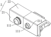
Fig. 1 is an assembled isometric view of a camera module provided by an embodiment of the present invention;
fig. 2 is an assembled front view of a camera module provided by an embodiment of the present invention;
fig. 3 is a schematic view of a first viewing angle of a camera module according to an embodiment of the present invention;
fig. 4 is a schematic view of a second viewing angle of a camera module according to an embodiment of the present invention;
fig. 5 is a schematic diagram of a third view angle of a camera module according to an embodiment of the present invention;
fig. 6 is a schematic diagram of a fourth view angle of a camera module according to an embodiment of the present invention;
fig. 7 is a schematic diagram of a fifth view angle of a camera module according to an embodiment of the present invention.
In the figure:
1. a camera assembly; 11. a camera; 111. a lens barrel; 112. a connecting structure;
2. a camera exterior; 21. a positioning part; 211. positioning holes; 22. a limiting part;
3. a camera support;
31. a bending section; 311. a first connection hole;
32. an abutting portion; 321. a connecting surface; 322. an abutting surface;
33. a connecting portion; 331. a second connection hole;
4. vehicle body outer decoration; 41. a limiting groove.
Detailed Description
The present invention will be described in further detail with reference to the accompanying drawings and examples. It is to be understood that the specific embodiments described herein are merely illustrative of the invention and are not limiting of the invention. It should be further noted that, for the convenience of description, only some of the structures related to the present invention are shown in the drawings, not all of the structures.
In the description of the present invention, unless otherwise explicitly specified or limited, the terms "connected", "connected" and "fixed" are to be construed broadly, e.g., as being fixedly connected, detachably connected, or integrated; can be mechanically or electrically connected; either directly or indirectly through intervening media, either internally or in any other relationship. The specific meaning of the above terms in the present invention can be understood in specific cases to those skilled in the art.
In the present disclosure, unless expressly stated or limited otherwise, the first feature "on" or "under" the second feature may comprise direct contact between the first and second features, or may comprise contact between the first and second features not directly. Also, the first feature being "on," "above" and "over" the second feature includes the first feature being directly on and obliquely above the second feature, or merely indicating that the first feature is at a higher level than the second feature. A first feature being "under," "below," and "beneath" a second feature includes the first feature being directly under and obliquely below the second feature, or simply meaning that the first feature is at a lesser elevation than the second feature.
In the description of the present embodiment, the terms "upper", "lower", "right", etc. are used in an orientation or positional relationship based on that shown in the drawings only for convenience of description and simplicity of operation, and do not indicate or imply that the device or element referred to must have a particular orientation, be constructed and operated in a particular orientation, and thus, should not be construed as limiting the present invention. Furthermore, the terms "first" and "second" are used only for descriptive purposes and are not intended to have a special meaning.
As shown in fig. 1 to 7, the camera module provided in the present embodiment includes a camera assembly 1, a camera exterior 2, and a camera mount 3. The camera assembly 1 comprises at least two cameras 11 arranged side by side; the camera exterior 2 is provided with a plurality of positioning holes 211, the positioning holes 211 correspond to the cameras 11 one by one, the lens barrels 111 of the cameras 11 are inserted into the positioning holes 211, and the camera exterior 2 is used for being spliced with the vehicle body exterior 4; the camera support 3 is located the camera subassembly 1 and keeps away from one side of camera exterior trim 2, and camera support 3 can dismantle with camera exterior trim 2 and be connected, and camera subassembly 1 presss from both sides and establishes between camera exterior trim 2 and camera support 3, and camera support 3 is used for being connected with automobile body exterior trim 4.
The camera module can be positioned on the vehicle body exterior trim 4 through the camera exterior trim 2, and can also be connected with the vehicle body exterior trim 4 through the camera exterior trim 2 and/or the camera support 3, and the connection mode can be determined according to needs. The camera exterior 2 can be embedded in the body exterior 4 by splicing so that the appearance can be maintained after the camera module is mounted. The camera exterior 2 and the camera support 3 of the camera module are respectively arranged on two sides of the camera component 1, the camera component 1 is fixed through clamping, the camera component 1, the camera exterior 2 and the camera support 3 form an integral camera module, and the camera component 1 is fixed on the vehicle body exterior 4 through the camera exterior 2 and the camera support 3. Through the location and the fixed action of camera exterior 2 and camera support 3, can make camera subassembly 1's stability improve, and then can optimize the shooting effect of unmanned driving or autopilot car.
When the camera module is assembled, accurate positioning can be realized only by aligning the lens cone 111 of the camera 11 and inserting the lens cone into the positioning hole 211 of the camera exterior trim 2, and the camera exterior trim 2 is small in size relative to the vehicle body exterior trim 4, convenient to mount, free from repeatedly adjusting the position of the lens cone 111 and simple to operate. Since the camera module 1 is not directly provided on the vehicle body, the need for positioning the camera 11 with the exterior body trim 4 can be avoided. When the camera assembly 1 needs to be disassembled, the camera module can be disassembled together, so that the camera assembly 1 can be detected and other operations, the positioning requirement during re-assembly is reduced, and the installation steps are simplified. When the camera module is used, the installation error exists between the camera outer decoration 2 and the vehicle body outer decoration 4, and the installation difficulty and the requirement for positioning of the camera assembly 1 cannot be improved. The camera module can ensure the position precision of the camera component 1, improve the unmanned or automatic driving shooting effect, and simultaneously enable the camera component 1 to be easily disassembled and assembled, and beautify the appearance.
Optionally, the camera assembly 1 comprises at least two cameras 11 of different focal lengths to be able to photograph the environment at different distances around the vehicle body.
With continued reference to fig. 1-7, optionally, the camera bracket 3 includes an abutting portion 32 and a bent portion 31 connected in a bent manner, the camera assembly 1 is sandwiched between the abutting portion 32 and the camera exterior 2, and the bent portion 31 is used for being detachably connected with the vehicle body exterior 4.
The bent portion 31 allows the camera mount 3 to be fixed to a mounting bracket of the vehicle body exterior 4, thereby achieving the purpose of fixing the camera module 1 and the camera exterior 2 to the vehicle body exterior 4. The bent portion 31 may be provided with a first connecting hole 311, and the camera bracket 3 may be connected to the exterior body 4 through the first connecting hole 311. Preferably, three first connection holes 311 may be provided, and the three first connection holes 311 are not collinear, so as to improve the fixing effect, and enable the camera assembly 1 to be stably connected to the body exterior 4. A gasket may be further disposed at the position of the first connection hole 311 on the bending portion 31 to improve the structural strength of the first connection hole 311. The bending part 31 can also be detachably connected by other methods such as clamping.
Optionally, one side of the camera bracket 3 facing the camera component 1 has a plurality of abutting surfaces 322, the abutting surfaces 322 correspond to the cameras 11 one by one, and at least two abutting surfaces 322 are disposed in a non-coplanar manner, and the cameras 11 are sandwiched between the abutting surfaces 322 and the camera exterior 2.
The camera support 3 further includes a plurality of connecting surfaces 321, the connecting surfaces 321 are disposed at two ends of the abutting surfaces 322 and can be used for connecting the two abutting surfaces 322, and the connecting surfaces 321 and the abutting surfaces 322 are disposed at a predetermined included angle.
In this embodiment, for example, two cameras 11 with different focal lengths are arranged, and the abutting surfaces 322 are in one-to-one correspondence with the cameras 11 and are used for cooperating with the camera exterior 2 to fix the cameras 11. Because the camera 11's of different focal lengths size is different, consequently with two butt faces 322 coplane not when setting up, for the camera 11 of different focal lengths provides sufficient accommodation space, satisfies the needs of shooing different distances around the automobile body, avoids causing the surface unevenness of camera exterior 2 because the difference of camera 11 focal length, influences the pleasing to the eye of outward appearance. Because two butt faces 322 are collineatly not, connect face 321 through setting up and realize connecting, connect face 321 simultaneously and can be with butt face 322 and predetermine the angle setting, preferably, connect face 321 and butt face 322 perpendicular setting, can improve butt portion 32's intensity when realizing the connection effect, make camera module non-deformable to can protect camera subassembly 1 to stably realize shooing the function.
Optionally, the abutting surface 322 is provided with an avoiding hole, and the connecting structure 112 of the camera 11 can extend out of the avoiding hole.
The shape of the avoiding hole matches with the shape of the connecting structure 112 arranged on the side of the camera 11 close to the abutting surface 322, and the connecting structure 112 may be a power supply connecting structure of the camera 11 or other structures required to be connected with the camera 11.
Optionally, the camera support 3 further includes a connecting portion 33, the connecting portion 33 is disposed on two sides of the abutting portion 32, and the camera support 3 can be connected to the camera exterior 2 through the connecting portion 33.
The connecting portion 33 and the contact surface 322 can be connected by a connecting surface 321 so that the contact portion 32 can be fixedly connected to the connecting portion 33. The connecting portion 33 may be provided with a second connecting hole 331, and a connecting mechanism capable of being matched with the second connecting hole 331 is provided at a corresponding position of the camera exterior 2 to achieve connection. Preferably, the edges of the connecting portion 33 are provided with rounded transitions to prevent scratching and the like. It can be understood that the connecting portion 33 can also be connected to the camera holder 3 and the camera exterior 2 by means of clamping, magnetic attraction, or the like.
Alternatively, the camera support 3 is integrally formed or assembled, the integrally formed camera support 3 has good stability and strength, and the assembly and disassembly of the camera support 3 are more convenient.
Optionally, the camera exterior 2 includes a positioning portion 21 and a limiting portion 22, the positioning portion 21 is provided with a positioning hole 211, the positioning portion 21 is used for abutting against one side of the camera 11 far away from the camera bracket 3, the limiting portion 22 is connected to the positioning portion 21, and the limiting portion 22 extends from the positioning portion 21 to one side close to the camera bracket 3.
The positioning hole 211 is sized to match the lens barrel 111 of the camera 11 to be fitted so that the lens barrel 111 can be extended to photograph the surroundings of the vehicle body. Preferably, the limiting part 22 and the positioning part 21 are arranged at a certain included angle, so that the limiting part 22 can be matched with the surface of the vehicle body exterior trim 4, and the appearance is beautified; meanwhile, the limiting part 22 can also limit the direction of the camera component 1 perpendicular to the axis of the lens barrel 111, so that the stability of the camera component 1 is improved. Preferably, the position limiting portion 22 may include, but is not limited to, a first position limiting portion extending along the arrangement direction of the two cameras 11, and a second position limiting portion perpendicular to the arrangement direction of the two cameras, and the first position limiting portion and the second position limiting portion can respectively limit the cameras 11 in different directions.
Alternatively, the camera mount 3 and the camera exterior 2 and the camera mount 3 and the body exterior 4 are connected by screws, bolts, or snap-fit. When disassembly is required, the camera module can be removed as a whole by detaching the connection between the camera mount 3 and the vehicle body exterior 4.
Another aspect of the utility model provides an unmanned vehicle, including automobile body exterior trim 4 and foretell camera module, be equipped with spacing groove 41 on the automobile body exterior trim 4, camera module inserts in the spacing groove 41 and is connected with the cell wall of spacing groove 41, and camera exterior trim 2 is located the notch department of spacing groove 41 and splices with automobile body exterior trim 4.
The exterior body 4 may be a bumper of a vehicle such as an unmanned vehicle, and the exterior body 4 is mounted on the vehicle body. The limiting groove 41 is formed in the proper position of the outer vehicle body decoration 4, and the camera module can be detachably connected to the outer vehicle body decoration 4 through the matching of the camera outer decoration 2 and the limiting groove 41 on the outer vehicle body decoration 4, so that the camera module is convenient to disassemble and assemble. The camera exterior 2 may be provided with a limiting structure to be assembled and connected with the limiting groove 41 through the limiting structure. It will be appreciated that the unmanned vehicle is provided with the necessary control and communication mechanisms to effect control of the camera 11.
It is obvious that the above embodiments of the present invention are only examples for clearly illustrating the present invention, and are not intended to limit the embodiments of the present invention. Numerous obvious variations, rearrangements and substitutions will now occur to those skilled in the art without departing from the scope of the invention. And are neither required nor exhaustive of all embodiments. Any modification, equivalent replacement or improvement made within the spirit and principle of the present invention should be included in the protection scope of the claims of the present invention.
Claims (10)
1. A camera module, comprising:
a camera assembly (1) comprising at least two cameras (11) arranged side by side;
the camera exterior trim (2) is provided with a plurality of positioning holes (211), the positioning holes (211) correspond to the cameras (11) one by one, the lens barrels (111) of the cameras (11) are inserted into the positioning holes (211), and the camera exterior trim (2) is used for being spliced with the automobile body exterior trim (4);
the camera support (3) is located on one side, away from the camera exterior (2), of the camera component (1), the camera support (3) is detachably connected with the camera exterior (2), the camera component (1) is clamped between the camera exterior (2) and the camera support (3), and the camera support (3) is used for being connected with the automobile body exterior (4).
2. The camera module according to claim 1, wherein the camera bracket (3) comprises an abutting portion (32) and a bending portion (31) which are connected in a bending manner, the camera assembly (1) is sandwiched between the abutting portion (32) and the camera exterior (2), and the bending portion (31) is detachably connected with the vehicle body exterior (4).
3. The camera module according to claim 2, wherein the side of the camera bracket (3) facing the camera component (1) has a plurality of abutting surfaces (322), the abutting surfaces (322) correspond to the cameras (11) one by one, and at least two abutting surfaces (322) are disposed non-coplanar, and the cameras (11) are sandwiched between the abutting surfaces (322) and the camera exterior (2).
4. The camera module according to claim 3, wherein the abutting surface (322) is provided with an avoiding hole, and the connecting structure (112) of the camera (11) extends out of the avoiding hole.
5. The camera module according to claim 2, characterized in that the camera holder (3) further comprises a connecting portion (33), the connecting portion (33) being provided on both sides of the abutting portion (32), the camera holder (3) being connectable to the camera exterior (2) through the connecting portion (33).
6. The camera module according to any one of claims 1 to 5, wherein the camera exterior (2) includes a positioning portion (21) and a limiting portion (22), the positioning portion (21) has the positioning hole (211), the positioning portion (21) is used for abutting against one side of the camera (11) away from the camera bracket (3), the limiting portion (22) is connected to the positioning portion (21), and the limiting portion (22) extends from the positioning portion (21) to one side close to the camera bracket (3).
7. A camera module according to any one of claims 1 to 5, characterised in that the camera support (3) is integrally formed or formed by assembly.
8. The camera module according to any of claims 1 to 5, characterized in that the camera mount (3) and the camera exterior (2) and the camera mount (3) and the body exterior (4) are connected or clamped by means of screws, bolts or clips.
9. The camera module according to any of claims 1 to 5, characterized in that the two cameras (11) have different focal lengths.
10. The unmanned vehicle is characterized by comprising an outer vehicle body decoration (4) and the camera module as claimed in any one of claims 1 to 9, wherein a limiting groove (41) is formed in the outer vehicle body decoration (4), the camera module is inserted into the limiting groove (41) and connected with the groove wall of the limiting groove (41), and the outer camera decoration (2) is positioned at the notch of the limiting groove (41) and spliced with the outer vehicle body decoration (4).
Priority Applications (1)
| Application Number | Priority Date | Filing Date | Title |
|---|---|---|---|
| CN202222664531.3U CN218258003U (en) | 2022-09-30 | 2022-09-30 | Camera module and unmanned vehicle |
Applications Claiming Priority (1)
| Application Number | Priority Date | Filing Date | Title |
|---|---|---|---|
| CN202222664531.3U CN218258003U (en) | 2022-09-30 | 2022-09-30 | Camera module and unmanned vehicle |
Publications (1)
| Publication Number | Publication Date |
|---|---|
| CN218258003U true CN218258003U (en) | 2023-01-10 |
Family
ID=84749712
Family Applications (1)
| Application Number | Title | Priority Date | Filing Date |
|---|---|---|---|
| CN202222664531.3U Active CN218258003U (en) | 2022-09-30 | 2022-09-30 | Camera module and unmanned vehicle |
Country Status (1)
| Country | Link |
|---|---|
| CN (1) | CN218258003U (en) |
-
2022
- 2022-09-30 CN CN202222664531.3U patent/CN218258003U/en active Active
Similar Documents
| Publication | Publication Date | Title |
|---|---|---|
| CN111045184B (en) | Lens assembly and camera module using thermal change driver and automatic focusing method thereof | |
| JP5793122B2 (en) | In-vehicle image processing device | |
| US20250362571A1 (en) | Imaging device including an imaging element, a mount, and members | |
| CN212064118U (en) | Binocular camera support and binocular camera with same | |
| CN205075725U (en) | On -vehicle night vision device | |
| US12477201B2 (en) | Camera module having a lens assembly with at least one flange projecting therefrom and assembling method | |
| US20240019768A1 (en) | Camera device | |
| WO2022052057A1 (en) | Vehicle-mounted multi-view structure and vehicle | |
| CN218258003U (en) | Camera module and unmanned vehicle | |
| CN103543573A (en) | Camera lens assembly | |
| CN209433092U (en) | A kind of optical lens for capableing of integrally-regulated lens assembly | |
| CN214799628U (en) | Novel binocular vehicle-mounted camera structure | |
| US20250115193A1 (en) | Attachment structure of onboard stereo camera unit | |
| KR20180085279A (en) | Camera module and vehicle | |
| US11175570B2 (en) | Mount for an image capturing device | |
| CN214851603U (en) | Binocular Stereo Vision Systems, Windshields and Vehicles | |
| CN110972517B (en) | Cameras, Filming Equipment and Movable Platforms | |
| CN217388801U (en) | Image pickup device, electronic apparatus, and vehicle | |
| CN222939377U (en) | PTZ camera with filter lens assembly and electronic equipment | |
| CN219821772U (en) | Visible light machine core mechanism of photoelectric pod and photoelectric pod thereof | |
| US12427922B2 (en) | Base assembly, rear view device carrying a camera, vehicle and assembling method | |
| CN219780270U (en) | Automatic focusing light source structure of multi-view camera | |
| CN210428053U (en) | Light filtering structure and camera | |
| CN205706435U (en) | Intelligent back vision mirror and there is the automobile of this intelligent back vision mirror | |
| CN221550945U (en) | Safety grating |
Legal Events
| Date | Code | Title | Description |
|---|---|---|---|
| GR01 | Patent grant | ||
| GR01 | Patent grant |