CN217990082U - A dual-detector rapid installation structure for intelligent sorting equipment - Google Patents
A dual-detector rapid installation structure for intelligent sorting equipment Download PDFInfo
- Publication number
- CN217990082U CN217990082U CN202123336651.2U CN202123336651U CN217990082U CN 217990082 U CN217990082 U CN 217990082U CN 202123336651 U CN202123336651 U CN 202123336651U CN 217990082 U CN217990082 U CN 217990082U
- Authority
- CN
- China
- Prior art keywords
- detector
- detectors
- rail assembly
- sliding rail
- slide rail
- Prior art date
- Legal status (The legal status is an assumption and is not a legal conclusion. Google has not performed a legal analysis and makes no representation as to the accuracy of the status listed.)
- Active
Links
Images


Landscapes
- Analysing Materials By The Use Of Radiation (AREA)
Abstract
本实用新型提供了一种智能分选设备用双探测器快速安装结构,所述智能分选设备包括:皮带,皮带上方平行设置两个X光源;皮带下方平行设置两个探测器,所述两个探测器与所述两个X光源的位置对应:所述双探测器快速安装结构包括:托板,在托板上平行设置的第一滑轨组件、第二滑轨组件,在所述第一滑轨组件上安装第一探测器,在所述第二滑轨组件上安装第二探测器。本实用新型通过设置两个探测器,降低了超长探测器的加工难度及成本,并且通过设置两个平行的滑轨组件,实现对双探测器的快速安装,且能方便地对两个探测器进行X方向、Y方向的位置调节,便于探测器的位置调整及维护。
The utility model provides a double-detector rapid installation structure for intelligent sorting equipment. The intelligent sorting equipment includes: a belt, two X light sources are arranged in parallel above the belt; two detectors are arranged in parallel under the belt, and the two A detector corresponds to the position of the two X light sources: the double detector quick installation structure includes: a pallet, a first slide rail assembly and a second slide rail assembly arranged in parallel on the pallet, on the first slide rail assembly A first detector is installed on a slide rail assembly, and a second detector is installed on the second slide rail assembly. The utility model reduces the processing difficulty and cost of super-long detectors by setting two detectors, and realizes the rapid installation of double detectors by setting two parallel slide rail components, and can conveniently install two detectors. The position adjustment of the detector in the X direction and the Y direction is convenient for the position adjustment and maintenance of the detector.
Description
技术领域technical field
本实用新型涉及一种双探测器快速安装结构,尤其是一种用于智能分选设备的双探测器的快速安装结构。The utility model relates to a quick installation structure of double detectors, in particular to a quick installation structure of double detectors used in intelligent sorting equipment.
背景技术Background technique
目前的智能分选设备通过皮带输送机机构布料,X射线的发射装置与接收装置分别在皮带的上下两侧,物料在运行至皮带尽头时,会带着皮带提供的水平初速度抛出,最后由布置于皮带尽头下方的执行机构进行对物料进行吹选。为了提高设备产量,CN213001309U“基于双X光源的宽体智能分选设备及其信号采集单元”公开了一种基于双X光源的宽体智能分选设备及其信号采集单元,在不改变通用分选设备高度的前提下,能解决现有技术中的X射线的照射范围不够宽的问题,该方案中设置两个X光发射器用于发射X射线到待识别物,X射线穿透待识别物后光强信号会有所衰减,设置在运输带下方的信号接收单元5采集衰减后的X射线并发送给后台的计算单元。The current intelligent sorting equipment distributes materials through the belt conveyor mechanism, and the X-ray emitting device and receiving device are respectively located on the upper and lower sides of the belt. When the material runs to the end of the belt, it will be thrown out with the horizontal initial velocity provided by the belt, and finally The material is blown by the actuator arranged under the end of the belt. In order to improve the output of equipment, CN213001309U "Wide-body intelligent sorting equipment and its signal acquisition unit based on double X light sources" discloses a wide-body intelligent sorting equipment and its signal acquisition unit based on double X light sources, without changing the general classification Under the premise of selecting the height of the equipment, it can solve the problem that the irradiation range of X-rays in the prior art is not wide enough. In this solution, two X-ray emitters are set to emit X-rays to the object to be identified, and the X-rays penetrate the object to be identified. Afterwards, the light intensity signal will be attenuated, and the
然而在实践中,在设置双X光源的情况下,作为信号接收单元的探测器,也需要设置较长的长度以使其与双X光源的辐射范围相匹配。这意味着探测器需要设计得非常长,对设备提出了更高的要求,也意味着更高成本。因此,通常提供双探测器设置用于此类情形。但是,在使用双探测器的情况下,如果将探测器直接通过框架固定,尽管此种方式简单有效,但探测器的安装和调试都非常困难,需要工人进到设备内部去拆装内部的固定部位,费时费力。However, in practice, in the case of dual X-ray sources, the detector as the signal receiving unit also needs to be provided with a longer length to match the radiation range of the dual X-ray sources. This means that the detector needs to be designed to be very long, which puts higher requirements on the equipment and means higher costs. Therefore, a dual detector setup is usually provided for such situations. However, in the case of using double detectors, if the detectors are fixed directly through the frame, although this method is simple and effective, the installation and debugging of the detectors are very difficult, requiring workers to enter the interior of the equipment to disassemble the internal fixing location, time-consuming and labor-intensive.
实用新型内容Utility model content
本实用新型系针对现有技术中上述问题而提出的解决方案。The utility model is a solution to the above-mentioned problems in the prior art.
本实用新型提供了一种智能分选设备用双探测器快速安装结构,所述智能分选设备包括:皮带,皮带上方平行设置两个X光源;皮带下方平行设置两个探测器,所述两个探测器与所述两个X光源的位置对应:所述双探测器快速安装结构包括:托板,在托板上平行设置的第一滑轨组件、第二滑轨组件,在所述第一滑轨组件上安装第一探测器,在所述第二滑轨组件上安装第二探测器。The utility model provides a double-detector rapid installation structure for intelligent sorting equipment. The intelligent sorting equipment includes: a belt, two X light sources are arranged in parallel above the belt; two detectors are arranged in parallel under the belt, and the two A detector corresponds to the position of the two X light sources: the double detector quick installation structure includes: a pallet, a first slide rail assembly and a second slide rail assembly arranged in parallel on the pallet, on the first slide rail assembly A first detector is installed on a slide rail assembly, and a second detector is installed on the second slide rail assembly.
作为优选,所述探测器可通过所述快速安装结构调整探测器的位置。Preferably, the detector can adjust the position of the detector through the quick installation structure.
作为优选,所述探测器可通过所述快速安装结构调整所述探测器的X方向及Y方向的位置。Preferably, the detector can adjust the position of the detector in the X direction and the Y direction through the quick installation structure.
作为优选,所述滑轨组件包括:安装调整块、滑块及滑轨,所述滑轨固定在所述托板上,所述滑块卡装在所述滑轨上并能沿着所述滑轨移动;所述安装调整块固定连接所述滑块及所述探测器。Preferably, the slide rail assembly includes: an installation adjustment block, a slide block and a slide rail, the slide rail is fixed on the support plate, the slide block is clamped on the slide rail and can move along the The slide rail moves; the installation adjustment block is fixedly connected with the slide block and the detector.
作为优选,所述安装固定块上设有安装固定孔及滑槽。Preferably, the mounting and fixing block is provided with mounting and fixing holes and sliding grooves.
作为优选,所述滑块上设有安装固定孔。Preferably, the slider is provided with mounting and fixing holes.
作为优选,所述滑块包括顶面部、立柱部及凹槽部,所述顶面部与所述安装固定孔连接;所述立柱部的圆弧形内面拼接形成所述滑块的凹槽部,用于容纳滑轨。Preferably, the slider includes a top surface, a column portion and a groove portion, the top surface is connected to the installation and fixing hole; the arc-shaped inner surface of the column portion is spliced to form the groove portion of the slider, Used to accommodate slide rails.
作为优选,所述立柱部为两个,分别位于所述顶面部的左右两侧,所述两个立柱部的底部间距小于所述凹槽部的直径。Preferably, there are two upright columns, which are respectively located on the left and right sides of the top surface, and the distance between the bottoms of the two upright columns is smaller than the diameter of the groove.
本实用新型通过设置两个探测器,降低了超长探测器的加工难度及成本,并且通过设置两个平行的滑轨组件,实现对双探测器的快速安装,且能方便地对两个探测器进行X方向、Y方向的位置调节,便于探测器的位置调整及维护。The utility model reduces the processing difficulty and cost of the ultra-long detector by setting two detectors, and realizes the rapid installation of the double detectors by setting two parallel slide rail components, and can conveniently install the two detectors. The position adjustment of the detector in the X direction and the Y direction is convenient for the position adjustment and maintenance of the detector.
附图说明Description of drawings
通过阅读下文优选实施方式的详细描述,各种其他的优点和益处对于本领域普通技术人员将变得清楚明了。附图仅用于示出优选实施方式的目的,而并不认为是对本实用新型的限制。而且在整个附图中,用相同的参考符号表示相同的部件。在附图中:Various other advantages and benefits will become apparent to those of ordinary skill in the art upon reading the following detailed description of the preferred embodiment. The drawings are only for the purpose of illustrating preferred embodiments, and are not considered to limit the present invention. Also throughout the drawings, the same reference numerals are used to designate the same parts. In the attached picture:
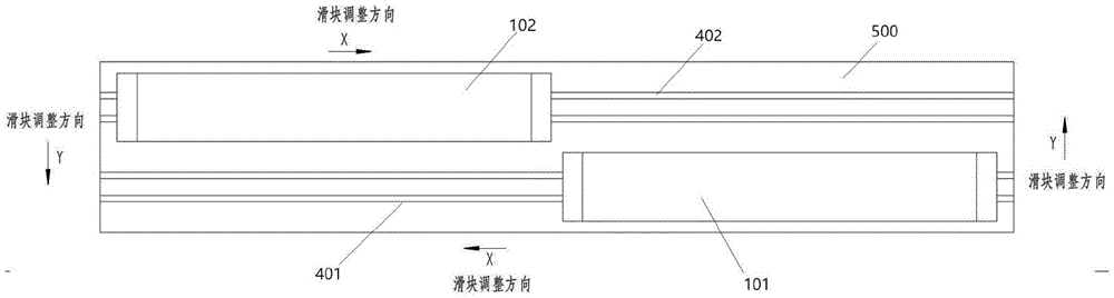
图1是根据本实用新型实施例提供的双探测器及其快速安装结构的俯视图;Fig. 1 is a top view of a dual detector and its quick installation structure provided according to an embodiment of the present invention;
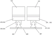
图2是根据本实用新型实施例提供的双探测器及其快速安装结构的主视图;Fig. 2 is a front view of a double detector and its quick installation structure provided according to an embodiment of the present invention;
图3是根据本实用新型实施例提供的双探测器的快速安装结构的调整方式示意图;Fig. 3 is a schematic diagram of the adjustment mode of the quick installation structure of the dual detectors provided according to the embodiment of the present invention;
图4是根据本实用新型实施例提供的快速安装结构的组装结构示意图;Fig. 4 is a schematic diagram of an assembly structure of a quick installation structure provided according to an embodiment of the present invention;
图5是根据本实用新型实施例提供的探测器安装调整块的俯视图;Fig. 5 is a top view of the detector installation adjustment block provided according to the embodiment of the present invention;
图6是根据本实用新型实施例提供的滑块的俯视图;Fig. 6 is a top view of a slider provided according to an embodiment of the present invention;
图7是根据本实用新型实施例提供的滑块的侧视图;Fig. 7 is a side view of a slider provided according to an embodiment of the present invention;
图8是现有技术中双X光源设置的X光源及探测器的结构示意图;Fig. 8 is a structural schematic diagram of an X light source and a detector with dual X light sources in the prior art;
图9是现有技术中探测器安装结构示意图。Fig. 9 is a schematic diagram of a detector installation structure in the prior art.
附图标记说明:Explanation of reference signs:
101-第一探测器,102-第二探测器;101-the first detector, 102-the second detector;
201-第一安装调整块;202-第二安装调整块;203-第三安装调整块;204-第四安装调整块;201-the first installation adjustment block; 202-the second installation adjustment block; 203-the third installation adjustment block; 204-the fourth installation adjustment block;
301-第一滑块,302-第二滑块,303-第三滑块,304-第四滑块;301-the first slider, 302-the second slider, 303-the third slider, 304-the fourth slider;
401-第一滑轨;402-第二滑轨;500-托板;401-the first slide rail; 402-the second slide rail; 500-supporting plate;
21-滑槽;22-安装固定孔;31a、31b、31c、31d-安装固定孔;31-顶面部;32a、32b-立柱部;33-凹槽部;21-chute; 22-installation and fixing holes; 31a, 31b, 31c, 31d-installation and fixing holes; 31-top face; 32a, 32b-column part; 33-groove part;
1-1-第一X光源,1-2-第二X光源;3-皮带;5-探测器。1-1-first X light source, 1-2-second X light source; 3-belt; 5-detector.
具体实施方式detailed description
下面将参照附图更详细地描述本公开的示例性实施例。虽然附图中显示了本公开的示例性实施例,然而应当理解,可以以各种形式实现本公开而不应被这里阐述的实施例所限制。相反,提供这些实施例是为了能够更透彻地理解本公开,并且能够将本公开的范围完整的传达给本领域的技术人员。需要说明的是,在不冲突的情况下,本实用新型中的实施例及实施例中的特征可以相互组合。下面将参考附图并结合实施例来详细说明本实用新型。Exemplary embodiments of the present disclosure will be described in more detail below with reference to the accompanying drawings. Although exemplary embodiments of the present disclosure are shown in the drawings, it should be understood that the present disclosure may be embodied in various forms and should not be limited by the embodiments set forth herein. Rather, these embodiments are provided for more thorough understanding of the present disclosure and to fully convey the scope of the present disclosure to those skilled in the art. It should be noted that, in the case of no conflict, the embodiments of the present invention and the features in the embodiments can be combined with each other. The utility model will be described in detail below with reference to the accompanying drawings and in conjunction with the embodiments.
如图8所示,是现有技术中双X光源设置的X光源及探测器的结构示意图,现有技术中已经出现针对智能分选设备设置双X光源的方案,智能分选设备通常包括给料部、皮带传输部、X光检测部、以及分选部。图8是智能分选设备中的X光检测部的结构示意图,可以看出,第一X光源1-1、第二X光源1-2设置在智能分选设备的顶部、皮带3的上方,并分别射出扇形X光束,两个X光源所辐射的扇形X光束的宽度叠加,能够覆盖皮带3的全部宽度。皮带3的下方为探测器5,探测器5用于探测来自第一X光源1-1以及第二X光源1-2的X光。As shown in Figure 8, it is a schematic structural diagram of an X light source and a detector with dual X light sources in the prior art. In the prior art, there have been solutions for setting dual X light sources for intelligent sorting equipment. Intelligent sorting equipment usually includes Material department, belt transmission department, X-ray detection department, and sorting department. Fig. 8 is a schematic structural diagram of the X-ray detection unit in the intelligent sorting device. It can be seen that the first X light source 1-1 and the second X light source 1-2 are arranged on the top of the intelligent sorting device and above the
如图9所示,是此类现有技术中探测器的安装方式,即将探测器置于探测器盒体中,并整体固定在智能分选设备的安装底板。此种方式的探测器的长度需相当于图8中皮带3的全部宽度,即能够与两个X光源所辐射的扇形光束的宽度的叠加值相当。这通常意味着探测器5需要做到足够长,对加工难度、加工成本、以及维护等均提出了较高的挑战。As shown in FIG. 9 , it is the installation method of the detector in this type of prior art, that is, the detector is placed in the detector box and fixed on the installation base plate of the intelligent sorting equipment as a whole. The length of the detector in this way needs to be equivalent to the entire width of the
本实用新型提出的智能分选设备解决方案中,将两个光源1-1、1-2相互错开一定距离,并相应地设置两个探测器。参见图1,在托板500上,设置两个探测器,分别为第一探测器101、第二探测器102,两个探测器的位置分别与两个X光源的位置相对应,相互平行并错开一定距离。需理解,托板500即为探测器的安装底板,其通常设置在皮带3的下方,固定在智能分选设备的框架上,用于提供对探测器的安装及支撑功能。In the intelligent sorting equipment solution proposed by the utility model, the two light sources 1-1, 1-2 are staggered by a certain distance from each other, and two detectors are arranged accordingly. Referring to Fig. 1 , on the
如图1所示,在托板500上,分别设置第一滑轨401、第二滑轨402,两个滑轨均固定在托板500上,相互平行并错开一定距离,第一滑轨401、第二滑轨402用于分别限制两个探测器的移动方向,并提供对第一探测器101、第二探测器102的支撑。As shown in Figure 1, on the
图2是图1所示双探测器及其快速安装结构的主视图,该图中可以看出,第一探测器101、第二探测器102的长度之和,基本覆盖托板500的宽度,以此方式,能够以较短的探测器的叠加,实现对较宽的皮带宽度范围(通常意味着智能分选设备更高的产量)的覆盖,从而可以在无需增加加工难度的情况下,提高设备的产量。Fig. 2 is a front view of the double detector and its quick installation structure shown in Fig. 1, it can be seen from this figure that the sum of the lengths of the
图2中,右侧的探测器101距离观察者更近,左侧的探测器102距离观察者更远,两个探测器的安装位置不同,但是安装结构是大致相同的,因此以第一探测器101的快速安装结构为例对本实用新型进行说明。In Fig. 2, the
如图2所示,第一探测器101为长形的盒体结构,在盒体结构内封装有用于探测X射线的传感器,因本实用新型不关注盒体内的传感器,故对其内容不做详细介绍,而以长形探测器盒指代探测器。在长形的第一探测器101的底部两端,分别设有第一安装调整块201、第二安装调整块202;第一安装调整块201与第一滑轨401通过第一滑块301连接;第二安装调整块202与第一滑轨401通过第二滑块302连接。As shown in Figure 2, the
与之相似,在长形的第二探测器102的底部两端,分别设有第三安装调整块203、第四安装调整块204,第三安装调整块203与第二滑轨402之间通过第三滑块303连接;第四安装调整块204与第二滑轨402之间通过第四滑块304连接。Similarly, at both ends of the bottom of the elongated
通过上述设置,第一探测器101、第二探测器102分别在第一滑轨401、第二滑轨402上滑动,从而可以实现对其位置的调整。Through the above arrangement, the
如图3所示,是本实用新型提供的双探测器的快速安装结构的调整方式示意图,如图所示,X方向为与探测器长度方向平行的方向,也是与皮带的宽度方向平行的方向,Y方向为与皮带运行方向平行的方向,X、Y方向相互垂直。通过本实用新型提供的双探测器的快速安装结构,一方面,两个探测器101、102分别沿着滑轨401、402滑动,可以实现在X方向的位置调整;另一方面,本实用新型提供的快速安装结构,也可以实现对两个探测器101、102分别在Y方向的位置调整。As shown in Figure 3, it is a schematic diagram of the adjustment method of the quick installation structure of the double detector provided by the utility model. As shown in the figure, the X direction is a direction parallel to the length direction of the detector, and is also a direction parallel to the width direction of the belt , the Y direction is parallel to the running direction of the belt, and the X and Y directions are perpendicular to each other. Through the fast installation structure of the double detectors provided by the utility model, on the one hand, the two
如图5所示,安装调整块201(其他的安装调整块202、203、204与201相同),包括安装固定孔22,用于提供探测器与安装调整块之间的固定连接;安装调整块201上还包括滑槽21,滑槽21贯通安装调整块,且优选为长椭圆形轨道,滑槽21为在Y方向上调整探测器的位置提供了空间和轨道。As shown in Figure 5, the installation adjustment block 201 (other installation adjustment blocks 202, 203, 204 are the same as 201), including installation fixing holes 22, are used to provide a fixed connection between the detector and the installation adjustment block; 201 also includes a
如图6所示,滑块301(其他的滑块302、303、304与301相同)上,设置有多个安装固定孔31a、31b、31c、31d等,用于提供安装调整块与滑块之间的固定连接。作为优选,通过螺栓将滑块上的安装固定孔与安装调整块上的滑槽之间固定连接,可以调整滑块与安装调整块之间的相对位置,并进而调整固定在安装调整块上的探测器与滑块之间的相对位置,从而实现对探测器在Y方向上的位置的调整。As shown in Figure 6, on the slider 301 (
如图7所示,是本实用新型提供的滑块的侧面结构示意图,图7中可见滑块包括顶面部31,立柱部32,以及凹槽部33,其中,顶面部31位于滑块的顶面,具有顶部平面,在该顶部平面上设置前述安装固定孔31a、31b、31c、31d等,以提供滑块与安装调整块之间的连接;从该顶部平面往下延伸,左右两侧分别为两个立柱部32a、32b,两个立柱部32a、32b分别具有直线型外面与圆弧形内面,并且,两个立柱部32a、32b的圆弧形内面拼接形成滑块的凹槽部33,该凹槽部33为圆弧形内面包围形成,以提供对滑轨的容纳功能,使得所述滑块通过滑动安装至滑轨时,滑轨位于滑块的凹槽部33。作为优选,两个立柱部32a、32b的底部间距小于凹槽部33的直径,以提供更稳固的支撑。As shown in Figure 7, it is a schematic diagram of the side structure of the slider provided by the utility model. In Figure 7, it can be seen that the slider includes a
本实用新型通过设置两个探测器,降低了超长探测器的加工难度及成本,并且通过设置两个平行的滑轨组件,实现对双探测器的快速安装,且能方便地对两个探测器进行X方向、Y方向的位置调节,便于探测器的位置调整及维护。The utility model reduces the processing difficulty and cost of the ultra-long detector by setting two detectors, and realizes the rapid installation of the double detectors by setting two parallel slide rail components, and can conveniently install the two detectors. The position adjustment of the detector in the X direction and the Y direction is convenient for the position adjustment and maintenance of the detector.
需要说明的是,在本实用新型的描述中,术语“上”、“下”、“左”、“右”、“内”、“外”等指示的方向或位置关系的术语是基于附图所示的方向或位置关系,这仅仅是为了便于描述,而不是指示或暗示所述装置或元件必须具有特定的方位、以特定的方位构造和操作,因此不能理解为对本实用新型的限制。此外,还需要说明的是,在本实用新型的描述中,除非另有明确的规定和限定,术语“安装”、“相连”、“连接”应做广义理解,例如,可以是固定连接,也可以是可拆卸连接,或一体地连接;可以是直接相连,也可以通过中间媒介间接相连,可以是两个元件内部的连通。显然,本领域的技术人员可以对本实用新型进行各种改动和变型而不脱离本实用新型的精神和范围。这样,倘若本实用新型的这些修改和变型属于本实用新型权利要求及其等同技术的范围之内,则本实用新型也意图包含这些改动和变型在内。It should be noted that, in the description of the present utility model, terms such as "upper", "lower", "left", "right", "inner", "outer" and other indicated directions or positional relationships are based on the accompanying drawings The directions or positional relationships shown are only for convenience of description, and do not indicate or imply that the device or element must have a specific orientation, be constructed and operated in a specific orientation, and thus should not be construed as limiting the present invention. In addition, it should be noted that, in the description of the present utility model, unless otherwise specified and limited, the terms "installation", "connection" and "connection" should be understood in a broad sense, for example, it can be a fixed connection, or It can be detachably connected or integrally connected; it can be directly connected or indirectly connected through an intermediary, and it can be internal communication between two components. Obviously, those skilled in the art can make various changes and modifications to the utility model without departing from the spirit and scope of the utility model. In this way, if these modifications and variations of the utility model fall within the scope of the claims of the utility model and equivalent technologies thereof, the utility model is also intended to include these modifications and variations.
Claims (8)
Priority Applications (1)
| Application Number | Priority Date | Filing Date | Title |
|---|---|---|---|
| CN202123336651.2U CN217990082U (en) | 2021-12-28 | 2021-12-28 | A dual-detector rapid installation structure for intelligent sorting equipment |
Applications Claiming Priority (1)
| Application Number | Priority Date | Filing Date | Title |
|---|---|---|---|
| CN202123336651.2U CN217990082U (en) | 2021-12-28 | 2021-12-28 | A dual-detector rapid installation structure for intelligent sorting equipment |
Publications (1)
| Publication Number | Publication Date |
|---|---|
| CN217990082U true CN217990082U (en) | 2022-12-09 |
Family
ID=84286394
Family Applications (1)
| Application Number | Title | Priority Date | Filing Date |
|---|---|---|---|
| CN202123336651.2U Active CN217990082U (en) | 2021-12-28 | 2021-12-28 | A dual-detector rapid installation structure for intelligent sorting equipment |
Country Status (1)
| Country | Link |
|---|---|
| CN (1) | CN217990082U (en) |
-
2021
- 2021-12-28 CN CN202123336651.2U patent/CN217990082U/en active Active
Similar Documents
| Publication | Publication Date | Title |
|---|---|---|
| JP3805254B2 (en) | Container inspection equipment | |
| JP5198575B2 (en) | Arm frame structure and radiation imaging system having arm frame structure | |
| JPH04274706A (en) | Thickness measuring apparatus | |
| KR20170135630A (en) | Safety inspection system | |
| CN103529060A (en) | Gantry structure used for combination movable type radiation inspection system | |
| CN217990082U (en) | A dual-detector rapid installation structure for intelligent sorting equipment | |
| US6618464B2 (en) | Thickness-measuring device | |
| WO2025131112A1 (en) | System and method for positioning detector of transmissive inspection device for receiving detection rays | |
| CN108414542A (en) | X-ray detection machines | |
| US10024810B2 (en) | On-belt analyser system | |
| CN202757895U (en) | Gantry structure used for combined movable radiation inspection system | |
| CN209961708U (en) | Double viewing angle ray inspection equipment | |
| CN106388847A (en) | Center indication assembly, PET-CT mounting rack and alignment method therefor | |
| KR101738102B1 (en) | An X-ray Investigating Apparatus With a Vision Device and A Method for Investigating A Board with the Same | |
| KR102106130B1 (en) | Inspection apparatus for portable speed detector | |
| JPH0712512A (en) | Two-dimensional coordinate measuring machine | |
| CN113739737A (en) | Double-end thickness measuring device | |
| WO2021259327A1 (en) | Movable inspection device and inspection method | |
| RU2367977C1 (en) | Transport portal radiation monitor | |
| CN1304037A (en) | Door frame scanning vehicle for mobile container inspection system | |
| CN116923476B (en) | Detecting equipment for turnout rail | |
| CN110320219B (en) | Ray detection system, detection equipment, mounting rack and detector mounting arm | |
| CN220085084U (en) | X-ray detection device | |
| CN206258071U (en) | Light-receiving component, light generating assembly, sensor and volume measurement device | |
| CN220323110U (en) | AOI equipment for detecting up and down of double conveying channels simultaneously |
Legal Events
| Date | Code | Title | Description |
|---|---|---|---|
| GR01 | Patent grant | ||
| GR01 | Patent grant | ||
| CP03 | Change of name, title or address |
Address after: 313301 Zhejiang Province Huzhou City Anji County Xiaofeng Town Bamboo Industry Demonstration Park (Qianshi No. 2 Road) (Zhuilong Bridge) Patentee after: Horizon Tech (Zhejiang) Co., Ltd. Country or region after: China Address before: Zhejiang Province Huzhou City Anji County Tianzihu Town Small and Medium-sized Enterprise Industrial Park Building 6 (Building of Anji Common Innovation Property Management Co., Ltd.) Patentee before: Huzhou Hollister Intelligent Technology Co.,Ltd. Country or region before: China |
|
| CP03 | Change of name, title or address |