CN217540437U - Working lamp - Google Patents
Working lamp Download PDFInfo
- Publication number
- CN217540437U CN217540437U CN202221328375.7U CN202221328375U CN217540437U CN 217540437 U CN217540437 U CN 217540437U CN 202221328375 U CN202221328375 U CN 202221328375U CN 217540437 U CN217540437 U CN 217540437U
- Authority
- CN
- China
- Prior art keywords
- seat
- pin joint
- lamp
- lamp body
- joint seat
- Prior art date
- Legal status (The legal status is an assumption and is not a legal conclusion. Google has not performed a legal analysis and makes no representation as to the accuracy of the status listed.)
- Active
Links
Images


Landscapes
- Fastening Of Light Sources Or Lamp Holders (AREA)
Abstract
本实用新型公开一种工作灯,在灯体的边缘固定安装云台;云台分为第一安装部和第二安装部;第一安装部的一端固定在灯体的边缘,第一安装部的另一端形成第一枢接座;第二安装部的一端形成第二枢接座,第二安装部的另一端形成供安装在固定座上的插接部;第一枢接座和第二枢接座通过第一紧固件枢接在一起,且第一枢接座与第二枢接座的相对面形成相互啮合的卡齿,第一枢接座与第二枢接座之间借助卡齿相互啮合固定。本实用新型使工作灯可以随意旋转,方便调节工作灯的照射角度和范围。所述灯体的边缘与云台的第一安装部通过插槽和插块、插销和销孔配合固定,使工作灯的云台可以方便拆装,使工作灯体积小,方便包装、运输和收藏。
The utility model discloses a work lamp. A pan/tilt head is fixedly installed on the edge of the lamp body; the pan/tilt head is divided into a first installation part and a second installation part; one end of the first installation part is fixed on the edge of the lamp body, and the first installation part The other end of the second mounting portion forms a first pivot seat; one end of the second mounting portion forms a second pivot seat, and the other end of the second mounting portion forms a plug portion for mounting on the fixed seat; the first pivot seat and the second The pivoting bases are pivotally connected together by a first fastener, and the opposite surfaces of the first pivoting base and the second pivoting base form mutually engaging locking teeth, and the first pivoting base and the second pivoting base are connected by means of The teeth are engaged with each other and fixed. The utility model enables the work light to be rotated at will, and it is convenient to adjust the irradiation angle and range of the work light. The edge of the lamp body and the first installation part of the pan/tilt are fixed through the slot, the insert block, the pin and the pin hole, so that the pan/tilt of the work light can be easily disassembled and assembled, so that the work light is small in size and convenient for packaging, transportation and maintenance. collect.
Description
技术领域technical field
本实用新型涉及灯具的技术领域,具体涉及一种工作灯,特别与工作灯的安装结构有关。The utility model relates to the technical field of lamps, in particular to a work light, in particular to the installation structure of the work light.
背景技术Background technique
现有技术中,户外野营用工作灯的灯体一般是先通过螺丝锁固在云台上,再将云台借助锁块紧固在三角架上,灯体的角度调节定位是依靠云台上的摩擦片来实现。由于螺丝锁固后不方便拆卸,所以,灯体和云台一经组装后就不再拆卸,云台和灯体一直保持固定形态,云台突出于灯体边缘,造成工作灯的体积变大,不方便包装、运输及收藏。而鉴于工作灯本身具有一定重量,体积也较大,依靠摩擦配合实现角度调节定位,这种固定方式本身不够牢固,难以将工作灯支撑在任意角度,想要调节工作灯照射角度或范围时,需要先解锁解除摩擦定位,然后将灯体旋转至合适的角度,再上锁固定,调节过程中,始终需要用手托住工作灯的灯体,避免灯体在自重作用下快速下翻,造成人员砸伤和产品损坏,安全性较差,操作存在难度,无法实现快速、准确定位工作灯。In the prior art, the lamp body of the work lamp for outdoor camping is generally first locked on the gimbal by screws, and then the gimbal is fastened on the tripod by means of a lock block, and the angle adjustment and positioning of the lamp body is based on the gimbal. the friction plate to achieve. Since it is inconvenient to disassemble after the screw is locked, the lamp body and the head will not be disassembled after they are assembled. It is inconvenient for packaging, transportation and collection. In view of the fact that the work light itself has a certain weight and a large volume, and relies on friction to achieve angle adjustment and positioning, this fixing method itself is not firm enough, and it is difficult to support the work light at any angle. When you want to adjust the illumination angle or range of the work light, It is necessary to unlock and release the friction positioning first, then rotate the lamp body to an appropriate angle, and then lock and fix it. During the adjustment process, it is always necessary to hold the lamp body of the work light by hand to prevent the lamp body from falling down rapidly under the action of its own weight, causing Personnel are injured and products are damaged, the safety is poor, the operation is difficult, and it is impossible to quickly and accurately locate the work light.
有鉴于此,本发明人凭借长期研究、设计、制造的专业技术水平与积累的丰富经验,以及对加工工艺的熟悉,经过反复设计、试验、修改和测试,开发了一种方便组装、拆卸、调节、定位的工作灯,本案由此产生。In view of this, the inventor has developed a convenient assembly, disassembly, Adjusted, positioned work lights, from which this case was born.
实用新型内容Utility model content
本实用新型的目的在于提供一种工作灯,使工作灯可以随意旋转,方便调节工作灯的照射角度和范围。The purpose of the utility model is to provide a work light, which can be rotated at will, and the illumination angle and range of the work light can be adjusted conveniently.
本实用新型的目的在于提供一种工作灯,使工作灯的云台可以方便拆装,使工作灯体积小,方便包装、运输和收藏。The purpose of the utility model is to provide a work light, so that the pan/tilt of the work light can be easily disassembled and assembled, so that the work light is small in size and convenient for packaging, transportation and storage.
为了实现上述目的,本实用新型的解决方案是:In order to achieve the above object, the solution of the present utility model is:
一种工作灯,在灯体的边缘固定安装云台;云台分为第一安装部和第二安装部;第一安装部的一端固定在灯体的边缘,第一安装部的另一端形成第一枢接座;第二安装部的一端形成第二枢接座,第二安装部的另一端形成供安装在固定座上的插接部;第一枢接座和第二枢接座通过第一紧固件枢接在一起,且第一枢接座与第二枢接座的相对面形成相互啮合的卡齿,第一枢接座与第二枢接座之间借助卡齿相互啮合固定。A work lamp, a head is fixedly installed on the edge of the lamp body; the head is divided into a first installation part and a second installation part; one end of the first installation part is fixed on the edge of the lamp body, and the other end of the first installation part forms a first pivoting seat; one end of the second mounting part forms a second pivoting seat, and the other end of the second mounting part forms an inserting part for mounting on the fixed seat; the first pivoting seat and the second pivoting seat pass through The first fasteners are pivoted together, and the opposite surfaces of the first pivot seat and the second pivot seat form intermeshing teeth, and the first pivot seat and the second pivot seat are engaged with each other by means of the teeth fixed.
所述第二枢接座位于第一枢接座的一侧,第一枢接座的另一侧设置一个夹片,第一枢接座与夹片的相对面也形成相互啮合的卡齿,第二枢接座、第一枢接座和夹片通过第一紧固件枢接在一起,第一枢接座与第二枢接座和夹片之间借助卡齿相互啮合固定。The second pivoting seat is located on one side of the first pivoting seat, a clip is arranged on the other side of the first pivoting seat, and the opposite surfaces of the first pivoting seat and the clip also form engaging teeth. The second pivoting seat, the first pivoting seat and the clip are pivotally connected together by a first fastener, and the first pivoting seat, the second pivoting seat and the clip are mutually engaged and fixed by means of the locking teeth.
所述第一紧固件的前端形成螺丝而中段形成压紧台,第二枢接座上形成螺孔,第一枢接座和夹片上形成通孔,夹片上还形成压紧槽,第一紧固件的前端螺丝锁紧在第二枢接座的螺孔中,第一紧固件的压紧台抵在夹片的压紧槽中。The front end of the first fastener is formed with a screw and the middle section is formed with a pressing table, a screw hole is formed on the second pivot seat, a through hole is formed on the first pivot seat and the clip, and a pressing groove is also formed on the clip. The front end screw of the fastener is locked in the screw hole of the second pivot seat, and the pressing platform of the first fastener is pressed against the pressing groove of the clip.
所述夹片上形成导向块,云台的第二安装部上形成导向槽,夹片借助导向块与导向槽配合而组装在云台的第二安装部上。A guide block is formed on the clip, a guide groove is formed on the second mounting part of the pan/tilt, and the clip is assembled on the second mounting part of the pan/tilt by means of the guide block and the guide groove.
所述灯体的边缘形成插槽,插槽上开设第一销孔,云台的第一安装部的一端上形成可插置在灯体插槽中的插块,插块上对应插槽的第一销孔形成第二销孔,通过插销插置在第一销孔和第二销孔中,使云台的第一安装部固定在灯体的边缘。The edge of the lamp body forms a slot, the slot is provided with a first pin hole, and an insert block that can be inserted into the lamp body slot is formed on one end of the first mounting part of the pan/tilt, and the insert block corresponds to the slot. The first pin hole forms a second pin hole, and the first mounting part of the pan/tilt head is fixed on the edge of the lamp body by inserting the plug in the first pin hole and the second pin hole.
所述插槽为槽底大而槽口小的形态,插槽的一端形成挡板,第一销孔开设在挡板上,插块为头大颈小的形态,可以呈T型,第二销孔形成在插块的端部。The slot is in the shape of a large slot bottom and a small slot, one end of the slot forms a baffle plate, the first pin hole is opened on the baffle plate, the insertion block is in the shape of a large head and a small neck, and can be T-shaped, and the second Pin holes are formed at the ends of the inserts.
所述插接部为插杆,固定座具有一个供插杆固定插置的插座和一个供安装在车顶帐篷边缘的底板,底板上安装第二螺栓,第二螺栓的头部连接可与车顶帐篷边缘卡槽配合的卡块。The plug-in part is a plug-in rod, and the fixed seat has a socket for the plug-in rod to be fixedly inserted and a bottom plate for installation on the edge of the roof tent. A second bolt is installed on the bottom plate, and the head of the second bolt can be connected with the vehicle. The card block that fits the card slot on the edge of the top tent.
所述插接部为插杆,固定座具有两个供插杆固定插置的插座和一个供三角架连接的插接管,两个插座呈一字型相对布设,插接管位于两个插座中间的下方,使固定座呈T字型。The plug-in part is a plug-in rod, and the fixed seat has two sockets for the plug-in rod to be fixedly inserted and a plug-in tube for the connection of the tripod. Below, make the fixing seat T-shaped.
所述灯体由主灯和副灯组成,主灯内置电池,副灯以磁吸等可拆卸的方式组装在主体上,副灯内置电池,或副灯经过端子与主灯电连接供电。The lamp body is composed of a main lamp and an auxiliary lamp, the main lamp has a built-in battery, the auxiliary lamp is assembled on the main body in a detachable manner such as magnetic suction, the auxiliary lamp has a built-in battery, or the auxiliary lamp is electrically connected to the main lamp through terminals for power supply.
所述灯体的背面安装太阳能电池板,太阳能电池板与主灯的控制电路连接供电。A solar panel is installed on the back of the lamp body, and the solar panel is connected with the control circuit of the main lamp to supply power.
采用上述方案后,本实用新型的云台由第一安装部和第二安装部构成,第一安装部和第二安装部可以随意做相对旋转,并可以借助卡齿相互啮合实现任意角度定位,这样,即可实现工作灯的随意旋转,方便工作灯的照射角度调节和定位,从而改变工作灯的照射范围,使工作灯的作用得到充分利用。After the above scheme is adopted, the pan/tilt of the present invention is composed of a first installation part and a second installation part, the first installation part and the second installation part can be freely rotated relative to each other, and can be positioned at any angle by means of the mutual meshing of the locking teeth, In this way, the random rotation of the work light can be realized, which facilitates the adjustment and positioning of the illumination angle of the work light, thereby changing the illumination range of the work light and making full use of the function of the work light.
另外,本实用新型使用组装时,灯体与云台之间通过插槽与插块配合、插销与销孔配合实现快速组装定位,运输包装或不使用收藏时,可以解除插销与销孔的配合,将灯体与云台拆分开;拆装操作方便,使工作灯的整体体积缩小,方便包装、运输和收藏。In addition, when the utility model is used and assembled, the lamp body and the pan/tilt can be quickly assembled and positioned through the cooperation between the slot and the insert block, and the cooperation between the plug and the pin hole. When the package is transported or the storage is not used, the cooperation between the plug and the pin hole can be released. , separate the lamp body from the head; easy disassembly and assembly operation, so that the overall volume of the work lamp is reduced, and it is convenient for packaging, transportation and collection.
附图说明Description of drawings
为了更清晰地说明本实用新型实例中的技术方案,下面对实施例描述中所需要使用的附图做简单的描述。应当理解,以下附图仅示出了本实用新型的某些实施例,因此不应被看作是对范围的限定,对于本领域普通技术人员来讲,在不付出创造性劳动的前提下,还可以根据这些附图获得其他相关的附图。In order to illustrate the technical solutions in the examples of the present invention more clearly, the following briefly describes the accompanying drawings that need to be used in the description of the embodiments. It should be understood that the following drawings only show some embodiments of the present invention, and therefore should not be regarded as a limitation of the scope. For those of ordinary skill in the art, without creative efforts, Other related figures can be obtained from these figures.
图1是本实用新型实施例一的立体分解图一;Fig. 1 is the perspective exploded view one of embodiment one of the present utility model;
图2是本实用新型实施例一的立体分解图二;Fig. 2 is the perspective exploded view two of the first embodiment of the present utility model;
图3是本实用新型实施例一的组装示意图;Fig. 3 is the assembly schematic diagram of the first embodiment of the present utility model;
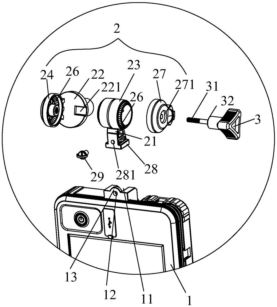
图4是本实用新型实施例一的局部放大图;4 is a partial enlarged view of
图5是本实用新型实施例二的立体分解图;5 is an exploded perspective view of
图6是本实用新型实施例二的使用状态示意图一;Fig. 6 is the schematic diagram 1 of the use state of the second embodiment of the present invention;
图7是本实用新型实施例二的使用状态示意图二。FIG. 7 is a second schematic diagram of the use state of the second embodiment of the present invention.
标号说明Label description
灯体1,插槽11,第一销孔12,挡板13,主灯14,副灯15,太阳能电池板16;
云台2,第一安装部21,第二安装部22,导向槽221,第一枢接座23,第二枢接座24,插接部25,卡齿26,夹片27,压紧槽271,导向块272,插块28,第二销孔281,插销29;The
第一紧固件3,螺丝31,压紧台32;The
固定座4,插座41,底板42,第二螺栓421,卡块422,插接管43。The
具体实施方式Detailed ways
为使本实用新型实施方式的目的、技术方案和优点更加清楚,下面将结合本实用新型实施方式中的附图,对本实用新型实施方式中的技术方案进行清楚、完整地描述,显然,所描述的实施方式是本实用新型一部分实施方式,而不是全部的实施方式。基于本实用新型中的实施方式,本领域普通技术人员在没有作出创造性劳动前提下所获得的所有其他实施方式,都属于本实用新型保护的范围。因此,以下对在附图中提供的本实用新型的实施方式的详细描述并非旨在限制要求保护的本实用新型的范围,而是仅仅表示本实用新型的选定实施方式。基于本实用新型中的实施方式,本领域普通技术人员在没有作出创造性劳动前提下所获得的所有其他实施方式,都属于本实用新型保护的范围。In order to make the purposes, technical solutions and advantages of the embodiments of the present invention more clear, the technical solutions in the embodiments of the present invention will be clearly and completely described below with reference to the accompanying drawings in the embodiments of the present invention. Obviously, the described The embodiments of the present invention are a part of the embodiments of the present invention, but not all of the embodiments. Based on the embodiments of the present invention, all other embodiments obtained by those of ordinary skill in the art without creative work fall within the protection scope of the present invention. Accordingly, the following detailed description of the embodiments of the invention provided in the accompanying drawings is not intended to limit the scope of the invention as claimed, but is merely representative of selected embodiments of the invention. Based on the embodiments of the present invention, all other embodiments obtained by those of ordinary skill in the art without creative work fall within the protection scope of the present invention.
需要说明的是,术语上、下、内、外、第一、第二等等仅用于描述目的,而不能理解为指示或暗示相对重要性或者隐含指明所指示的技术特征,除非另有明确具体的限定。It should be noted that the terms upper, lower, inner, outer, first, second, etc. are only used for descriptive purposes, and should not be construed as indicating or implying relative importance or implicitly indicating the indicated technical features, unless otherwise Specify specific limits.
如图1至图7所示,本实用新型揭示了一种工作灯,在灯体1的边缘固定安装云台2。云台2分为第一安装部21和第二安装部22;第一安装部21的一端固定在灯体1的边缘,第一安装部21的另一端形成第一枢接座23;第二安装部22的一端形成第二枢接座24,第二安装部22的另一端形成插接部25,插接部25用于安装在固定座4上;第一枢接座23和第二枢接座24通过第一紧固件(实施例中采用第一螺栓)3枢接在一起,使第一安装部21和第二安装部22之间可以随意做相对旋转,且第一枢接座23与第二枢接座24的相对面形成相互啮合的卡齿26,第一枢接座23与第二枢接座24之间借助卡齿26相互啮合固定而实现任意角度定位。这样,工作灯可以随意旋转,调节合适的照射角度后再定位,从而改变工作灯的照射范围,使工作灯的作用得到充分利用。As shown in FIG. 1 to FIG. 7 , the present invention discloses a work lamp, and a
为了更好调节定位工作灯,本实用新型进一步将所述第二枢接座24设计成位于第一枢接座23的一侧,第一枢接座23的另一侧设置一个夹片27,第一枢接座23与夹片27的相对面也形成相互啮合的卡齿26,这样,第一枢接座23位于第二枢接座24和夹片27的中间,第二枢接座24、第一枢接座23和夹片27通过第一紧固件3枢接在一起时,第一枢接座23与第二枢接座24和夹片27之间分别借助卡齿26相互啮合固定,使第一安装部21和第二安装部22之间角度定位,从而实现工作灯的角度调节定位。In order to better adjust the positioning of the work light, the present invention further designs the
为了调节操作更方便、准确,本实用新型所述第一紧固件3的前端形成螺丝31而中段形成压紧台32,第二枢接座24上形成螺孔,第一枢接座23和夹片27上形成通孔,夹片27上还形成压紧槽271,第一紧固件3穿过的通孔后,前端螺丝31锁紧在第二枢接座24的螺孔中,第一紧固件3的压紧台32抵在夹片27的压紧槽271中,可以更准确地定位夹片27。In order to make the adjustment operation more convenient and accurate, the front end of the
为了方便夹片27组装定位,本实用新型进一步在所述夹片27上形成导向块272,云台2的第二安装部22上形成导向槽221,夹片27借助导向块272与导向槽221配合,可以快速准确地组装在云台2的第二安装部22上,而且,在工作灯角度调节过程中,借助导向块272与导向槽221配合,也可以避免夹片27随意转动,方便调节后的快速定位。In order to facilitate the assembly and positioning of the
本实用新型所述第一安装部21和灯体1边缘的固定方式可以有多种形态,为了方便拆分云台2和灯体1,此实施例进一步在所述灯体1的边缘形成插槽11,插槽11上开设第一销孔12,云台2的第一安装部21的一端上形成插块28,插块28可插置在灯体1的插槽11中,插块28上对应插槽11的第一销孔12形成第二销孔281,通过插销29插置在第一销孔12和第二销孔281中,使云台2的第一安装部21以可拆卸的方式固定在灯体1的边缘。这样,本实用新型使用组装时,通过插槽11与插块28配合、插销29与第一销孔12和第二销孔281配合,实现灯体1与云台2之间的快速组装定位。本实用新型运输包装或不使用、欲收藏时,可以解除插销29与第一销孔12和第二销孔281的配合,将灯体1与云台2拆分开,拆装操作方便,使工作灯的整体体积缩小,方便包装、运输和收藏。The fixing methods of the first mounting
进一步,为了方便操作,本实用新型所述插槽11设计为槽底大而槽口小的形态,插槽11的一端形成挡板13,第一销孔12开设在挡板13上,插块28为头大颈小的形态,可以呈T型,第二销孔281形成在插块28的端部,这样,操作起来更加方便。Further, in order to facilitate the operation, the
本实用新型云台2的插接部25与固定座4的安装方式可以有多种形态。本文列举两个具体实施例进行说明。The installation methods of the plug portion 25 and the fixing
实施例一,所述插接部25为插杆,固定座4具有一个供插杆固定插置的插座41和一个供安装在车顶帐篷边缘的底板42,底板42上安装第二螺栓421,第二螺栓421的头部连接可与车顶帐篷边缘卡槽配合的卡块422。借助底板42的卡块422与车顶帐篷边缘卡槽配合,可以将固定座4安装在车顶帐篷边缘,从而将工作灯安装在车顶帐篷边缘,方便工作灯在车顶帐篷周边的使用。
实施例二,所述插接部25为插杆,固定座4具有两个供插杆固定插置的插座41和一个供三角架连接的插接管43,两个插座41呈一字型相对布设,插接管43位于两个插座41中间的下方,使固定座4呈T字型。借助插接管43与三角架连接,可以将固定座4安装在三角架上,固定座4的两个插座41可以各安装一个工作灯,也可以根据需要选择其中一个插座41安装一个工作灯,方便工作灯的使用,而且,使用时两个工作灯可以转成水平排布或者垂直向下排布。In the second embodiment, the plug-in part 25 is a plug-in rod, and the fixing
本实用新型的所述灯体1可以为一个整灯,也可以如图所示由主灯14和副灯15组成,主灯14内置电池,副灯15以磁吸等可拆卸的方式组装在主体14上,副灯15可以像主灯14一样内置电池,或副灯15经过端子与主灯14电连接供电。本实用新型所述灯体1的背面还可以安装太阳能电池板16,由太阳能电池板16与主灯14的控制电路连接供电。The
另外,所述插接部25也可以采用插管或者其他结构,以便与三角架等直接连接,本文不予图未及不做赘述。In addition, the plug-in portion 25 may also adopt an intubation tube or other structures, so as to be directly connected with a tripod, etc., which will not be described in detail herein.
以上所述仅为本实用新型的实施示例,并非对本实用新型保护范围的限制。应当指出,本领域的技术人员在阅读完本说明书后,依本案的设计思路所做的等同变化,均落入本案的保护范围。The above descriptions are only examples of the implementation of the present invention, and are not intended to limit the protection scope of the present invention. It should be pointed out that after reading this specification, the equivalent changes made by those skilled in the art according to the design ideas of this case all fall into the protection scope of this case.
Claims (10)
Priority Applications (1)
| Application Number | Priority Date | Filing Date | Title |
|---|---|---|---|
| CN202221328375.7U CN217540437U (en) | 2022-05-30 | 2022-05-30 | Working lamp |
Applications Claiming Priority (1)
| Application Number | Priority Date | Filing Date | Title |
|---|---|---|---|
| CN202221328375.7U CN217540437U (en) | 2022-05-30 | 2022-05-30 | Working lamp |
Publications (1)
| Publication Number | Publication Date |
|---|---|
| CN217540437U true CN217540437U (en) | 2022-10-04 |
Family
ID=83441366
Family Applications (1)
| Application Number | Title | Priority Date | Filing Date |
|---|---|---|---|
| CN202221328375.7U Active CN217540437U (en) | 2022-05-30 | 2022-05-30 | Working lamp |
Country Status (1)
| Country | Link |
|---|---|
| CN (1) | CN217540437U (en) |
Cited By (2)
| Publication number | Priority date | Publication date | Assignee | Title |
|---|---|---|---|---|
| US12455065B2 (en) | 2023-08-25 | 2025-10-28 | Milwaukee Electric Tool Corporation | Work light |
| USD1101238S1 (en) | 2024-05-01 | 2025-11-04 | Milwaukee Electric Tool Corporation | Work light |
-
2022
- 2022-05-30 CN CN202221328375.7U patent/CN217540437U/en active Active
Cited By (2)
| Publication number | Priority date | Publication date | Assignee | Title |
|---|---|---|---|---|
| US12455065B2 (en) | 2023-08-25 | 2025-10-28 | Milwaukee Electric Tool Corporation | Work light |
| USD1101238S1 (en) | 2024-05-01 | 2025-11-04 | Milwaukee Electric Tool Corporation | Work light |
Similar Documents
| Publication | Publication Date | Title |
|---|---|---|
| CN217540437U (en) | Working lamp | |
| EP0572733B1 (en) | Portable fluorescent lighting system | |
| CN210004277U (en) | portable outdoor emergency light of formula of accomodating | |
| CN206191437U (en) | Office up and down luminous line lights | |
| CN220540938U (en) | Multi-functional little night-light of xiang embroidery | |
| CN210860887U (en) | New multi-purpose LED lamps | |
| CN214533233U (en) | A kind of multi-channel monitoring equipment for diesel generator set | |
| CN219571760U (en) | Locking structure and box storage device thereof | |
| CN218442102U (en) | Assembled lampshade | |
| CN222184270U (en) | An outdoor container that is easy to assemble | |
| CN218895344U (en) | Detachable desk lamp convenient to store | |
| CN221076230U (en) | Multipurpose lamp structure | |
| CN222773218U (en) | Multipurpose solar lamp | |
| CN219530682U (en) | State adjusting device and emergency lighting equipment thereof | |
| CN222669894U (en) | Lighting device and quick assembly disassembly lamps and lanterns thereof | |
| CN215764974U (en) | Portable outdoor intelligent lamp bracket | |
| CN216242788U (en) | Water supply and drainage HVAC fixed installation structure for buildings | |
| CN210860890U (en) | Quick installation type LED projection lamp | |
| CN213930627U (en) | Combined wall lamp | |
| CN218671939U (en) | Portable explosion-proof lamp | |
| CN211625037U (en) | A lamp | |
| CN211551542U (en) | Lighting modular assembly | |
| CN222047572U (en) | A panel light without dismantling the original lamp panel | |
| CN220958194U (en) | Straight tube lamp with rotatable lamp cap | |
| CN217464320U (en) | Fast assembling and disassembling rotary folding fastener |
Legal Events
| Date | Code | Title | Description |
|---|---|---|---|
| GR01 | Patent grant | ||
| GR01 | Patent grant | ||
| PE01 | Entry into force of the registration of the contract for pledge of patent right | ||
| PE01 | Entry into force of the registration of the contract for pledge of patent right |
Denomination of utility model: A type of work light Granted publication date: 20221004 Pledgee: Bank of China Limited Xiamen Haicang sub branch Pledgor: Mainhouse (Xiamen) Electronics Co.,Ltd. Registration number: Y2025980015477 |