CN217488735U - A guide and protection device for the central puncture rod of the digestive tract tubular stapler - Google Patents
A guide and protection device for the central puncture rod of the digestive tract tubular stapler Download PDFInfo
- Publication number
- CN217488735U CN217488735U CN202220384851.0U CN202220384851U CN217488735U CN 217488735 U CN217488735 U CN 217488735U CN 202220384851 U CN202220384851 U CN 202220384851U CN 217488735 U CN217488735 U CN 217488735U
- Authority
- CN
- China
- Prior art keywords
- guiding
- puncture rod
- protecting
- central
- alimentary canal
- Prior art date
- Legal status (The legal status is an assumption and is not a legal conclusion. Google has not performed a legal analysis and makes no representation as to the accuracy of the status listed.)
- Active
Links
Images


Landscapes
- Surgical Instruments (AREA)
Abstract
本实用新型涉及一种用于消化道管型吻合器中心穿刺杆的引导及保护装置,包括引导保护鞘及限位圈,引导保护鞘的一端为引导保护鞘头端,另一端为引导保护鞘尾端,该引导保护鞘尾端沿轴向开设有与管型吻合器的中心穿刺杆相适配的穿刺杆容置腔,限位圈设置在穿刺杆容置腔内,并与中心穿刺杆相适配。与现有技术相比,本实用新型利用其在消化道管型吻合器中心穿刺杆表面形成保护,同时引导其行进路线,可避免中心穿刺杆损伤粘膜、撕裂组织等,并可通过引导达到预定位置。
The utility model relates to a guiding and protecting device for the central puncture rod of an alimentary canal stapler, comprising a guiding protective sheath and a limit ring. One end of the guiding protective sheath is the head end of the guiding protective sheath, and the other end is the guiding protective sheath The tail end of the guide protection sheath is axially provided with a puncture rod accommodating cavity which is adapted to the central puncture rod of the tubular stapler. fit. Compared with the prior art, the utility model utilizes it to form protection on the surface of the central puncture rod of the alimentary canal stapler, and guide its travel route at the same time, so as to avoid the central puncture rod from damaging the mucosa, tearing the tissue, etc. Predetermined location.
Description
技术领域technical field
本实用新型属于医疗用品技术领域,涉及一种用于消化道管型吻合器中心穿刺杆的引导及保护装置。The utility model belongs to the technical field of medical supplies, and relates to a guiding and protecting device for the central puncture rod of a digestive tract tubular stapler.
背景技术Background technique
普外科手术常常需要进行消化道的吻合重建,而管型吻合器则是目前消化道吻合过程中使用最为普遍的医疗器械,通过管型吻合器器身与钉砧头相结合激发钉仓后完成吻合。General surgery often requires anastomosis and reconstruction of the digestive tract, and the tubular stapler is the most commonly used medical device in the process of anastomosis of the digestive tract. match.
然而,在部分手术中,管型吻合器器身中心杆在穿出过程中,容易损伤消化道壁,造成组织撕裂或粘膜损伤,特别是在深部视野无法到达的部位,在穿出消化道时,更容易导致损伤与穿孔,进而造成手术失败或并发症发生率增加,降低了手术安全性。However, in some surgeries, the central rod of the tubular stapler can easily damage the alimentary canal wall, causing tissue tearing or mucosal damage, especially in the parts that cannot be reached by deep vision. It is more likely to cause injury and perforation, resulting in increased surgical failure or increased complication rates, reducing surgical safety.
实用新型内容Utility model content
本实用新型的目的是提供一种用于消化道管型吻合器中心穿刺杆的引导及保护装置,该装置能够使手术更加顺畅,减少手术并发症,提高手术成功率。The purpose of the present utility model is to provide a guiding and protecting device for the central puncture rod of an alimentary canal stapler, which can make the operation smoother, reduce the complications of the operation and improve the success rate of the operation.
本实用新型的目的可以通过以下技术方案来实现:The purpose of the present utility model can be achieved through the following technical solutions:
一种用于消化道管型吻合器中心穿刺杆的引导及保护装置,该装置包括引导保护鞘及限位圈,所述的引导保护鞘的一端为引导保护鞘头端,另一端为引导保护鞘尾端,该引导保护鞘尾端沿轴向开设有与管型吻合器的中心穿刺杆相适配的穿刺杆容置腔,所述的限位圈设置在穿刺杆容置腔内,并与中心穿刺杆相适配。中心穿刺杆的头部可插入穿刺杆容置腔中,并通过限位圈与中心穿刺杆侧面凹槽的配合,对中心穿刺杆进行轴向限位。A guiding and protecting device for the central puncture rod of an alimentary canal stapler, the device comprises a guiding protective sheath and a limit ring, one end of the guiding protective sheath is the head end of the guiding protective sheath, and the other end is the guiding protective sheath The tail end of the sheath, the tail end of the guiding and protecting sheath is axially provided with a puncture rod accommodating cavity adapted to the central puncture rod of the tubular stapler, and the limit ring is arranged in the puncture rod accommodating cavity, and Compatible with the central puncture rod. The head of the central puncture rod can be inserted into the accommodating cavity of the puncture rod, and the central puncture rod can be axially limited through the cooperation of the limit ring with the groove on the side of the central puncture rod.
进一步地,所述的穿刺杆容置腔的内壁上开设有限位圈放置槽,所述的限位圈嵌设在限位圈放置槽中。限位圈与限位圈放置槽的尺寸相匹配。Further, the inner wall of the puncture rod accommodating cavity is provided with a limiting ring placing groove, and the limiting ring is embedded in the limiting ring placing groove. The stop ring matches the size of the stop ring placement slot.
进一步地,所述的引导保护鞘的外表面呈光滑状。引导保护鞘可以由PVC、PPS、PEEK、ABS、PC等医用高分子制成。Further, the outer surface of the guiding and protecting sheath is smooth. The guiding protective sheath can be made of medical polymer such as PVC, PPS, PEEK, ABS, PC, etc.
进一步地,所述的限位圈为弹性限位圈。限位圈可以由硅胶、橡胶、TPU等具有弹性的医用材料制成。限位圈由柔性医用高分子制成,管型吻合器中心穿刺杆穿过限位圈后可以将本实用新型与管型吻合器中心穿刺杆形成限位固定,需要拆除时也可以达到快速拔除的效果。Further, the limit ring is an elastic limit ring. The limit ring can be made of elastic medical materials such as silicone, rubber, TPU, etc. The limit ring is made of flexible medical polymer. After the central puncture rod of the tubular stapler passes through the limit ring, the utility model and the central puncture rod of the tubular stapler can be limited and fixed, and can also be quickly removed when it needs to be removed. Effect.
进一步地,所述的限位圈呈环形。Further, the limiting ring is annular.
进一步地,所述的限位圈的外径为1-8mm。Further, the outer diameter of the limiting ring is 1-8mm.
进一步地,所述的引导保护鞘的外径为2-10mm。Further, the outer diameter of the guiding and protecting sheath is 2-10 mm.
进一步地,所述的穿刺杆容置腔的直径(即引导保护鞘的内径)为1-8mm。引导保护鞘的内径适配管型吻合器中心穿刺杆的外径。Further, the diameter of the accommodating cavity of the puncture rod (ie, the inner diameter of the guiding protective sheath) is 1-8 mm. The inner diameter of the guide sheath is adapted to the outer diameter of the central puncture rod of the tubular stapler.
进一步地,所述的引导保护鞘头端的端面与穿刺杆容置腔的之间的距离为1-15mm。使用时,引导保护鞘头端超过管型吻合器中心穿刺杆头端1-15mm,以防止管型吻合器中心穿刺杆损伤粘膜、撕裂组织。Further, the distance between the end face of the head end of the guiding and protecting sheath and the accommodating cavity of the puncture rod is 1-15 mm. When in use, the head end of the guiding protective sheath exceeds the head end of the central puncture rod of the tubular stapler by 1-15 mm, so as to prevent the central puncturing rod of the tubular stapler from damaging the mucosa and tearing the tissue.
进一步地,所述的引导保护鞘头端呈圆柱形、椭球形、球形、水滴形或设有上翘结构。引导保护鞘可选为圆柱形,也可以选择设置上翘结构来达到在手术过程中牵引暴露所需吻合位置的效果。为了达到更好的引导及保护作用,引导保护鞘头端也可以为其他适合结构,如椭球形、球型、水滴形等。Further, the head end of the guiding and protecting sheath is cylindrical, ellipsoid, spherical, drop-shaped or provided with an upturned structure. The guiding and protecting sheath can be selected to be cylindrical, or an upturned structure can be selected to achieve the effect of pulling and exposing the desired anastomotic position during the operation. In order to achieve better guidance and protection, the head end of the guide and protection sheath can also be other suitable structures, such as ellipsoid, spherical, teardrop shape, and the like.
本实用新型可以通过3D打印、高分子注塑、机加工等方式加工成型。The utility model can be processed and formed by means of 3D printing, polymer injection molding, machining and the like.
本实用新型可以贴合于管型吻合器器身的中心穿刺杆头部,装置头端呈钝性,表面光滑,使管型吻合器器身在消化道行进过程中保护其中心穿刺杆尖端,避免其损伤粘膜、撕裂组织等,并能起到加长引导的功能。The utility model can fit on the head of the central puncture rod of the tubular stapler body, the head end of the device is blunt and the surface is smooth, so that the tubular stapler body can protect the tip of the central puncture rod during the process of the alimentary canal advancing, It can avoid damage to the mucosa, tear tissue, etc., and can play the function of lengthening and guiding.
与现有技术相比,本实用新型具有以下特点:Compared with the prior art, the utility model has the following characteristics:
1)本实用新型利用其在消化道管型吻合器中心穿刺杆表面形成保护,同时引导其行进路线,可避免中心穿刺杆损伤粘膜、撕裂组织等,并可通过引导达到预定位置。1) The utility model uses it to form protection on the surface of the central puncture rod of the alimentary canal type stapler, and guide its travel route at the same time, which can avoid the central puncture rod from damaging the mucosa, tearing the tissue, etc., and can reach a predetermined position through guidance.
2)本实用新型结构简单,制造成本低,可以有效降低由于肠壁粘膜损伤撕裂所引起的并发症,减少病患恢复时间和痛苦,并易于临床推广。2) The utility model has the advantages of simple structure and low manufacturing cost, which can effectively reduce the complications caused by the damage and tear of the intestinal wall mucosa, reduce the recovery time and pain of patients, and is easy for clinical promotion.
附图说明Description of drawings
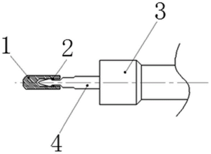
图1为本实用新型在应用时的结构示意图;Fig. 1 is the structural representation of the utility model in application;
图2为本实用新型中引导保护鞘的结构示意图;Fig. 2 is the structural representation of guiding protective sheath in the utility model;
图3为本实用新型中限位圈的结构示意图;Fig. 3 is the structural representation of the limit ring in the utility model;
图4为本实用新型中引导保护鞘头端设置上翘结构的示意图;4 is a schematic diagram of the upturned structure provided at the head end of the guide protection sheath in the utility model;
图中标记说明:Description of marks in the figure:
1—引导保护鞘、101—引导保护鞘头端、102—引导保护鞘尾端、103—穿刺杆容置腔、104—限位圈放置槽、2—限位圈、3—管型吻合器、4—中心穿刺杆。1—Guide protective sheath, 101—Guide protective sheath head end, 102—Guide protective sheath tail end, 103—Puncture rod accommodating cavity, 104—Limiting ring placement groove, 2—Limiting ring, 3—Tubular stapler , 4—Central puncture rod.
具体实施方式Detailed ways
下面结合附图和具体实施例对本实用新型进行详细说明。本实施例以本实用新型技术方案为前提进行实施,给出了详细的实施方式和具体的操作过程,但本实用新型的保护范围不限于下述的实施例。The present utility model will be described in detail below with reference to the accompanying drawings and specific embodiments. This embodiment is implemented on the premise of the technical solution of the present invention, and provides a detailed implementation manner and a specific operation process, but the protection scope of the present invention is not limited to the following embodiments.
实施例:Example:
如图1、图2、图3所示,一种用于消化道管型吻合器中心穿刺杆的引导及保护装置,包括引导保护鞘1及限位圈2。引导保护鞘1的一端为引导保护鞘头端101,另一端为引导保护鞘尾端102,该引导保护鞘尾端102沿轴向开设有与管型吻合器3的中心穿刺杆4相适配的穿刺杆容置腔103,限位圈2设置在穿刺杆容置腔103内,并与中心穿刺杆4相适配。As shown in FIGS. 1 , 2 and 3 , a guiding and protecting device for the central puncture rod of an alimentary canal stapler includes a guiding
其中,穿刺杆容置腔103的内壁上开设有限位圈放置槽104,限位圈2设置在限位圈放置槽104中。Wherein, the inner wall of the puncture rod accommodating
引导保护鞘1的外表面呈光滑状。引导保护鞘1的外径为2-10mm。穿刺杆容置腔103的直径为1-8mm。引导保护鞘头端101的端面与穿刺杆容置腔103的之间的距离为1-15mm。The outer surface of the
限位圈2为弹性限位圈。限位圈2呈环形。限位圈2的外径为1-8mm。The
引导保护鞘头端101呈圆柱形、椭球形、球形、水滴形或设有如图4所示的上翘结构。The
管型吻合器3在常规的使用过程中,主要步骤为取下护顶板、取下钉砧、调节中心穿刺杆4位置,之后将本装置套入中心穿刺杆4头部,并通过限位圈2将本装置与中心穿刺杆4固定。再将管型吻合器3置入所需吻合肠道内,后续手术过程中管型吻合器3在肠壁内移动并接触肠壁粘膜或组织时,引导保护鞘1可以起到保护肠壁粘膜及组织的效用,当后续确认中心穿刺杆4与钉砧位置相匹配时,可以通过手术钳或用手直接移除本装置,继而进行最后的吻合动作。In the conventional use process of the
上述的对实施例的描述是为便于该技术领域的普通技术人员能理解和使用实用新型。熟悉本领域技术的人员显然可以容易地对这些实施例做出各种修改,并把在此说明的一般原理应用到其他实施例中而不必经过创造性的劳动。因此,本实用新型不限于上述实施例,本领域技术人员根据本实用新型的揭示,不脱离本实用新型范畴所做出的改进和修改都应该在本实用新型的保护范围之内。The above description of the embodiments is for the convenience of those skilled in the art to understand and use the utility model. It will be apparent to those skilled in the art that various modifications to these embodiments can be readily made, and the generic principles described herein can be applied to other embodiments without inventive step. Therefore, the present invention is not limited to the above-mentioned embodiments, and improvements and modifications made by those skilled in the art according to the disclosure of the present invention without departing from the scope of the present invention should all fall within the protection scope of the present invention.
Claims (10)
Priority Applications (1)
| Application Number | Priority Date | Filing Date | Title |
|---|---|---|---|
| CN202220384851.0U CN217488735U (en) | 2022-02-24 | 2022-02-24 | A guide and protection device for the central puncture rod of the digestive tract tubular stapler |
Applications Claiming Priority (1)
| Application Number | Priority Date | Filing Date | Title |
|---|---|---|---|
| CN202220384851.0U CN217488735U (en) | 2022-02-24 | 2022-02-24 | A guide and protection device for the central puncture rod of the digestive tract tubular stapler |
Publications (1)
| Publication Number | Publication Date |
|---|---|
| CN217488735U true CN217488735U (en) | 2022-09-27 |
Family
ID=83346240
Family Applications (1)
| Application Number | Title | Priority Date | Filing Date |
|---|---|---|---|
| CN202220384851.0U Active CN217488735U (en) | 2022-02-24 | 2022-02-24 | A guide and protection device for the central puncture rod of the digestive tract tubular stapler |
Country Status (1)
| Country | Link |
|---|---|
| CN (1) | CN217488735U (en) |
-
2022
- 2022-02-24 CN CN202220384851.0U patent/CN217488735U/en active Active
Similar Documents
| Publication | Publication Date | Title |
|---|---|---|
| US7540875B2 (en) | Surgical cutting tool with automatically retractable blade assembly | |
| CN102510746B (en) | Tympanic membrane pressure equalization tube delivery system | |
| JP4674975B2 (en) | Endoscope hood | |
| JP6510503B2 (en) | Inserter for tubular medical implant devices | |
| CN100382770C (en) | Therapeutic device for endoscopic mucosal resection and endoscopic mucosal resection device | |
| US20030009185A1 (en) | Method and apparatus for placing and maintaining a percutaneous tube into a body cavity | |
| CN102596061B (en) | Circumcision device | |
| JP2003299663A (en) | Endoscope inserting system | |
| WO2006129726A1 (en) | Device and method for mucosal detachment | |
| JP2016521624A5 (en) | ||
| US12251545B2 (en) | Injection analgesia system | |
| US20220265948A1 (en) | Tracheotomy Device and Method of Use | |
| JPWO2006057402A1 (en) | Endovascular obstacle remover | |
| CN217488735U (en) | A guide and protection device for the central puncture rod of the digestive tract tubular stapler | |
| JP2005007161A (en) | EMR treatment tool and EMR device | |
| CN102018549B (en) | Percutaneous tracheotomy device | |
| CN115869489B (en) | An endoscopic intravenous injection needle | |
| CN201939442U (en) | A percutaneous tracheostomy | |
| CN209018883U (en) | A kind of anti-slip laparoscopic trocar | |
| CN101953701B (en) | Percutaneous tracheotomy device | |
| CN201905970U (en) | A percutaneous tracheostomy | |
| CN209499853U (en) | Pulmonary module puncture positioning device | |
| JP2012029788A (en) | Dilator for gastrostomy | |
| CN202637044U (en) | A minimally invasive percutaneous tracheostomy | |
| CN202619803U (en) | A blade type percutaneous tracheotomy device |
Legal Events
| Date | Code | Title | Description |
|---|---|---|---|
| GR01 | Patent grant | ||
| GR01 | Patent grant |