CN217364683U - Heating element and atomizer - Google Patents
Heating element and atomizer Download PDFInfo
- Publication number
- CN217364683U CN217364683U CN202221326891.6U CN202221326891U CN217364683U CN 217364683 U CN217364683 U CN 217364683U CN 202221326891 U CN202221326891 U CN 202221326891U CN 217364683 U CN217364683 U CN 217364683U
- Authority
- CN
- China
- Prior art keywords
- section
- cavity
- resistance heating
- embedded
- heating
- Prior art date
- Legal status (The legal status is an assumption and is not a legal conclusion. Google has not performed a legal analysis and makes no representation as to the accuracy of the status listed.)
- Active
Links
Images


Landscapes
- Resistance Heating (AREA)
Abstract
The heating component comprises a first support and a resistance heating sheet at least partially embedded in the first support, wherein a cavity and two bosses positioned outside the cavity are arranged on the first support in a penetrating mode, the resistance heating sheet stretches across the cavity, and two electrode parts of the resistance heating sheet are attached to the end faces of the bosses. The utility model discloses a heating element's simple structure, production simple process. The utility model discloses still relate to an atomizer.
Description
Technical Field
The utility model relates to an electronic atomization technical field, in particular to heating element and atomizer.
Background
The atomizer is the core part of the electronic atomization product, and the reliability of the quality of the atomizer determines the quality of the whole atomization product.
One of the existing atomization structures is: the ceramic porous material surface is printed and covered with heating slurry or embedded with a metal resistance heating element; in both the two modes, the porous ceramic is used as an oil guide material to adsorb the tobacco tar to the surface of the resistance heating element, and the resistance heating element generates heat when being electrified to work so as to atomize the tobacco tar; the ceramic with the atomized structure has the defects of complex forming process, low yield, poor consistency of the ceramic, high product cost, poor oil conductivity of the ceramic, easy generation of burnt flavor, poor mouthfeel reduction degree and the like.
Another existing atomization structure is: the spiral resistance heating wire is wound on the surface of the transverse cotton core, tobacco tar is adsorbed to the surface of the resistance heating wire by the transverse cotton core, and heat is generated when the resistance heating wire is electrified to work, so that the tobacco tar is atomized; the horizontal cotton core of atomizing structure of this mode is extremely easy to be out of shape and causes the equipment difficulty, leads to oily long distance moreover and easily produces burnt flavor.
Yet another existing atomization structure is: the outer surface of the vertical cotton core resistance heating element is wrapped with oil guide cotton, and the inner side of the resistance heating element is in a hollow state; the oil guide cotton wrapped on the outer surface absorbs the tobacco tar to the surface of the resistance heating element, and generates heat when the resistance heating wire is electrified to work, so that the tobacco tar is atomized; the atomization structure vertical cotton core structure has the advantages of multiple parts and complex assembly, so that the product cost is high.
Above, the existing atomization structure can not meet the requirements of quality stability and automatic production of products.
SUMMERY OF THE UTILITY MODEL
In view of this, the utility model provides a heating element, simple structure, production simple process.
The heating component comprises a first support and a resistance heating sheet at least partially embedded in the first support, wherein a cavity and two bosses positioned outside the cavity are arranged on the first support in a penetrating mode, the resistance heating sheet stretches across the cavity, and two electrode parts of the resistance heating sheet are attached to the end faces of the bosses.
The utility model discloses an in the embodiment, above-mentioned resistance generate heat the upper surface of piece with the chamber wall formation of chamber way accepts the chamber, resistance generate heat the piece the lower surface with the chamber wall formation atomizing chamber of chamber way.
The utility model discloses an in the embodiment, be equipped with the plummer on the chamber wall of above-mentioned chamber way, the plummer encircles the chamber way sets up, the resistance generates heat the piece and is close to the partial setting in chamber wall is in on the plummer.
In an embodiment of the present invention, the resistance heating sheet includes a heating portion, the heating portion includes two embedding portions disposed opposite to each other and a hollow portion connected between the two embedding portions, and the hollow portion is provided with a plurality of through holes; the embedding part comprises a plurality of embedding pins which are arranged at intervals, the embedding pins are at least partially embedded into the first support, a gap is formed between every two adjacent embedding pins, and the gap is at least partially suspended between the accommodating cavity and the atomizing cavity.
In an embodiment of the present invention, the embedded pin includes a first suspended section, a first bearing section and a first embedded section, and the first bearing section is connected between the first suspended section and the first embedded section; the upper surface of the first suspending section is exposed in the containing cavity, the lower surface of the first suspending section is exposed in the atomizing cavity, the upper surface of the first bearing section is attached to the bearing platform, the lower surface of the first bearing section is exposed in the atomizing cavity, the first embedding section is embedded in the first support, or the upper surface of the first suspending section is exposed in the containing cavity, the lower surface of the first suspending section is exposed in the atomizing cavity, the upper surface of the first bearing section is exposed in the containing cavity, the lower surface of the first bearing section is in contact with the bearing platform in an attaching mode, and the first embedding section is embedded in the first support.
In an embodiment of the present invention, a plurality of first spacers are disposed in the cavity, the first spacers are disposed corresponding to the notches, one end of each first spacer is fixed to a cavity wall of the cavity, the other end of each first spacer extends into the notch, a part of each first spacer is fixed on the carrier, and the other part of each first spacer opposite to the corresponding first spacer fills a part of the notch in a suspended manner; the upper surfaces of the first spacing pieces and the upper surfaces of the resistance heating pieces are located on the same horizontal plane, and the lower surfaces of the first spacing pieces and the lower surfaces of the resistance heating pieces are located on the same horizontal plane.
The embodiment of the utility model provides an in, above-mentioned resistance heating element still includes two connecting portion, the portion that generates heat is connected in two between the connecting portion, connecting portion include second unsettled section, two second carrier segments and two second embedding sections, the unsettled section of second is connected in two between the second carrier segment, two the second embedding section respectively with two the second carrier segment is connected.
The utility model discloses an in the embodiment, the upper surface of above-mentioned second suspension section expose in accept in the chamber, the lower surface of second suspension section expose in the atomizing chamber, the upper surface of second bearing section expose in accept in the chamber, the lower surface of second bearing section with plummer laminating contact, the second buries the section and buries in the first support.
In the embodiment of the utility model, above-mentioned resistance heating element still includes two kinks, each the kink is connected in each connecting portion and each between the electrode portion, the kink includes first linkage segment and second linkage segment, the one end of first linkage segment with the unsettled section of second is connected, the other end of first linkage segment with the second linkage segment is connected perpendicularly, the second linkage segment with the perpendicular connection of electrode portion.
The utility model discloses an in the embodiment, the upper surface of above-mentioned first linkage segment expose in accept in the chamber, the lower surface of first linkage segment expose in the atomizing chamber, first linkage segment with the junction of second linkage segment corresponds the plummer setting, the second linkage segment along the direction of height setting of boss.
In an embodiment of the present invention, a plurality of second spaced pieces are disposed in the cavity, one end of each of the second spaced pieces is fixed to the cavity wall of the cavity, the other end of each of the second spaced pieces extends to the edges of the first connecting section and the connecting section, and a part of each of the second spaced pieces is fixed to the carrier; the upper surfaces of the second spacing pieces and the upper surfaces of the resistance heating sheets are positioned on the same horizontal plane, and the lower surfaces of the second spacing pieces and the lower surfaces of the resistance heating sheets are positioned on the same horizontal plane.
In an embodiment of the present invention, the above-mentioned heating assembly further includes at least one first sealing ring, the first sealing ring is fixed to the outer wall of the first support and surrounds the circumferential direction of the first support.
The utility model discloses still relate to an atomizer, including foretell heating element and lead oily cotton, it sets up to lead oily cotton accept in the chamber, lead oily cotton lower surface with the upper surface laminating contact of resistance heating element.
The utility model discloses a heating element's resistance heating element combines with first support embedding, simple structure, and production simple process has improved the stability of production efficiency and product effectively, effectively ensures heating element's quality uniformity.
Drawings
Fig. 1 is a schematic structural diagram of the heating assembly of the present invention.
Fig. 2 is a schematic structural diagram of another view angle of the heat generating component shown in fig. 1.
Fig. 3 is a schematic view of a disassembled structure of the heat generating component shown in fig. 1.
Fig. 4 is a schematic view of a disassembled structure of the heat generating component shown in fig. 2.
Fig. 5 is a schematic cross-sectional view of the heating assembly of the present invention along the first direction.
Fig. 6 is a schematic sectional view of another region of the heat generating component along the first direction according to the present invention.
Fig. 7 is a schematic sectional view of the heating assembly of the present invention along the second direction.
Fig. 8 is a schematic view of the split structure of the atomizer according to the present invention.
Fig. 9 is a schematic view of the atomizer according to the present invention showing a split structure in another direction.
Fig. 10 is a schematic structural view of the heating element of the present invention after being butted with the second bracket.
Fig. 11 is a schematic cross-sectional view of the heat generating component and the second bracket shown in fig. 10.
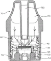
Fig. 12 is a schematic cross-sectional view of the atomizer of the present invention along one direction.
Fig. 13 is a schematic sectional view of the atomizer of the present invention in another direction.
Detailed Description
The utility model provides a heating assembly.
In order to make the technical solution of the present invention better understood, the technical solution of the embodiments of the present invention will be clearly and completely described below with reference to the accompanying drawings in the embodiments of the present invention, and it is obvious that the described embodiments are only some embodiments of the present invention, not all embodiments. Based on the embodiments in the present invention, all other embodiments obtained by a person skilled in the art without creative efforts shall belong to the protection scope of the present invention.
In order to facilitate understanding of those skilled in the art, the present invention provides a specific implementation process of the technical solution provided by the present invention through the following embodiments.
Fig. 1 is a schematic structural diagram of a heating assembly of the present invention, fig. 2 is a schematic structural diagram of another view angle of the heating assembly shown in fig. 1, fig. 3 is a schematic structural diagram of a split structure of the heating assembly shown in fig. 1, fig. 4 is a schematic structural diagram of a split structure of the heating assembly shown in fig. 2, please refer to fig. 1 to 4, the heating assembly 10 includes a first support 12 and a resistance heating sheet 13 at least partially embedded in the first support 12, for example, the resistance heating sheet 13 is at least partially embedded in the first support 12 by injection molding, a cavity channel 101 and two bosses 121 located outside the cavity channel 101 run through the first support 12, the resistance heating sheet 13 spans the cavity channel 101, and two electrode portions 132 of the resistance heating sheet 13 are attached to end surfaces of the bosses 121. In the present embodiment, the resistance heat generating sheet 13 is made of a metal thin sheet, such as an alloy material of nichrome, iron-chromium-aluminum, S316L stainless steel, or the like; the first support 12 is made of plastic, rubber or silicone.
The utility model discloses a heating element 10's resistance heating plate 13 combines with the embedding of first support 12, simple structure, and production simple process has improved the stability of production efficiency and product effectively, effectively ensures heating element 10's quality uniformity.
Optionally, the upper surface of the resistive heating sheet 13 and the cavity wall of the cavity 101 form an accommodating cavity 1011, and the lower surface of the resistive heating sheet 13 and the cavity wall of the cavity 101 form an atomizing cavity 1012.
Optionally, the upper surface of resistance heating piece 13 is the plane, and when will leading oily cotton 30 and installing in acceping the chamber 1011, the lower surface 31 of leading oily cotton 30 and the upper surface laminating contact of resistance heating piece 13 effectively promote atomization effect, produce when avoiding atomizing and stick with paste the flavor and influence the taste of sucking. Moreover, the oil guide cotton 30 and the heating assembly 10 are simple and convenient to assemble, automatic assembly and production can be realized, the resistance heating sheet 13 is not easy to deform, and the stability of the product is high.
Optionally, a bearing table 122 is disposed on a cavity wall of the cavity 101, the bearing table 122 is disposed around the cavity 101, and a portion of the resistance heating sheet 13 close to the cavity wall is disposed on the bearing table 122, for example, an upper surface of the resistance heating sheet 13 close to the cavity wall is disposed on the bearing table 122, or a lower surface of the resistance heating sheet 13 close to the cavity wall is disposed on the bearing table 122, which can be freely designed according to actual needs. In the present embodiment, the surface of the susceptor 122 contacting the resistance heating sheet 13 is a plane.
Optionally, the first bracket 12 includes an upper shell and a lower shell, a lower end surface of the upper shell is fixedly connected with an upper end surface of the lower shell, a portion of the lower end surface of the upper shell, which is not connected with the lower shell, forms the bearing table 122, or a portion of the upper end surface of the lower shell, which is not connected with the upper shell, forms the bearing table 122; the two bosses 121 are fixedly connected to the lower end surface of the lower housing, the two bosses 121 are formed by partially extending downward from the lower housing, and the inner walls of the bosses 121 are coplanar with the wall of the atomizing chamber 1012. In the present embodiment, the two bosses 121 are symmetrically disposed along the long axis direction of the first bracket 12; the upper case, the lower case, and the boss 121 are integrally formed by injection molding.
Alternatively, as shown in fig. 3 and 4, the resistance heating sheet 13 includes a heating portion 131, the heating portion 131 includes two embedded portions 1311 disposed opposite to each other and a perforated portion 1316 connected between the two embedded portions 1311, and the perforated portion 1316 is provided with a plurality of through holes 102; the embedding part 1311 includes a plurality of embedding pins 1312 disposed at intervals, the embedding pins 1312 are at least partially embedded in the first bracket 12, a gap 103 is formed between two adjacent embedding pins 1312, and the gap 103 is at least partially suspended between the accommodating cavity 1011 and the atomizing cavity 1012. When the heat generating portion 131 is powered on, both the perforated portion 1316 and the embedded portion 1311 generate heat, or only the perforated portion 1316 generates heat. In the present embodiment, a resistance heating element is disposed between two adjacent through holes 102, and the resistance heating element is in a shape of filament, strip, or bend, but not limited thereto; each through hole 102 communicates with the housing chamber 1011 and the atomizing chamber 1012.
Optionally, fig. 5 is a schematic cross-sectional structure view of the heating assembly of the present invention along a first direction, as shown in fig. 3, 4 and 5, the embedded pin 1312 includes a first suspending section 1313, a first carrying section 1314 and a first embedding section 1315, and the first carrying section 1314 is connected between the first suspending section 1313 and the first embedding section 1315; the upper surface of the first suspension section 1313 is exposed in the accommodating cavity 1011, the lower surface of the first suspension section 1313 is exposed in the atomizing cavity 1012, the upper surface of the first carrying section 1314 is attached to the carrying platform 122, the lower surface of the first carrying section 1314 is exposed in the atomizing cavity 1012, the first embedding section 1315 is embedded in the first support 12, or the upper surface of the first suspension section 1313 is exposed in the accommodating cavity 1011, the lower surface of the first suspension section 1313 is exposed in the atomizing cavity 1012, the upper surface of the first carrying section 1314 is exposed in the accommodating cavity 1011, the lower surface of the first carrying section 1314 is attached to the carrying platform 122, and the first embedding section 1315 is embedded in the first support 12.
Optionally, as shown in fig. 3, fig. 4, and fig. 5, a plurality of first spacers 123 are disposed in the channel 101, and are corresponding to each notch 103, one end of each first spacer 123 is fixed to the cavity wall of the channel 101, the other end of each first spacer 123 extends into the notch 103, a part of each first spacer 123 is fixed on the carrier 122, and the other part of each first spacer 123 is suspended to fill a part of the area of the notch 103.
Alternatively, the upper surface of the first spacers 123 and the upper surface of the resistance heat generating sheet 13 are located on the same horizontal plane, and the lower surface of each first spacer 123 and the lower surface of the resistance heat generating sheet 13 are located on the same horizontal plane, that is, the thickness of the first spacers 123 is equal to the thickness of the resistance heat generating sheet 13. In the embodiment, a part of the upper surface of the first spacer 123 is fixed on the bearing platform 122, and another part is exposed in the accommodating cavity 1011; the lower surfaces of the first spacers 123 are exposed in the atomizing chamber 1012.
Optionally, fig. 6 is a schematic cross-sectional structure view of another region of the heat generating component along the first direction, as shown in fig. 3, fig. 4 and fig. 6, the resistance heat generating sheet 13 further includes two connecting portions 133, the heat generating portion 131 is connected between the two connecting portions 133, the connecting portions 133 include a second suspending section 1331, two second carrying sections 1332 and two second embedding sections 1333, the second suspending section 1331 is connected between the two second carrying sections 1332, the two second embedding sections 1333 are respectively connected with the two second carrying sections 1332, and the second embedding section 1333 is embedded in the first bracket 12.
Optionally, the upper surface of the second suspension section 1331 is exposed in the accommodating cavity 1011, the lower surface of the second suspension section 1331 is exposed in the atomizing cavity 1012, the upper surface of the second carrying section 1332 is attached to the carrying table 122, and the lower surface of the second carrying section 1332 is exposed in the atomizing cavity 1012, or the upper surface of the second suspension section 1331 is exposed in the accommodating cavity 1011, the lower surface of the second suspension section 1331 is exposed in the atomizing cavity 1012, the upper surface of the second carrying section 1332 is exposed in the accommodating cavity 1011, and the lower surface of the second carrying section 1332 is attached to the carrying table 122.
Optionally, fig. 7 is a schematic cross-sectional structure view of the heating assembly along the second direction, as shown in fig. 3, fig. 4 and fig. 7, the resistance heating sheet 13 further includes two bending portions 134, each bending portion 134 is connected between each connecting portion 133 and each electrode portion 132, each bending portion 134 includes a first connecting section 1341 and a second connecting section 1342, one end of the first connecting section 1341 is connected to the second suspending section 1331, the other end of the first connecting section 1341 is vertically connected to the second connecting section 1342, and the second connecting section 1342 is vertically connected to the electrode portion 132; the upper surface of the first connection section 1341 is exposed in the receiving cavity 1011, the lower surface of the first connection section 1341 is exposed in the atomizing cavity 1012, the connection between the first connection section 1341 and the second connection section 1342 is disposed corresponding to the carrier 122, the second connection section 1342 is disposed along the height direction of the boss 121, and the second connection section 1342 is in contact with the cavity wall of the atomizing cavity 1012 and the inner wall of the boss 121 in a fitting manner.
Optionally, a plurality of second spacers 124 are disposed in the cavity 101, one end of the second spacer 124 is fixed to the cavity wall of the cavity 101, the other end of the second spacer 124 is connected to the first connecting segment 1341 and the edge of the connecting portion 133, and a portion of the second spacer 124 is fixed on the carrier 122; the upper surfaces of the second separation sheets 124 and the upper surface of the resistance heating sheet 13 are located on the same horizontal plane, and the lower surfaces of the second separation sheets 124 and the lower surface of the resistance heating sheet 13 are located on the same horizontal plane, that is, the thickness of the second separation sheets 124 is equal to the thickness of the resistance heating sheet 13; when the oil cotton 30 is attached to and attached to the plurality of first spacers 123, the plurality of second spacers 124, the heat generating portion 131, and the connecting portion 133, the plurality of first spacers 123 and the plurality of second spacers 124 have a certain supporting function for the oil cotton 30, and thus the heat generating portion 131 and the connecting portion 133 are not easily deformed even if a large force is applied to the heat generating portion 131 and the connecting portion 133 by the oil cotton 30. In the present embodiment, a portion of the upper surface of the second spacer 124 is fixed on the carrier 122, and another portion is exposed in the receiving cavity 1011; the lower surfaces of the second spaced apart webs 124 are exposed in the nebulizing chamber 1012.
Optionally, the first connecting segment 1341 includes opposite first and second sides, the connecting portion 133 includes a third side connected to the first connecting segment 1341, right-angle gaps are formed between the first and third sides and between the second and third sides, the second spaced apart spacers 124 completely fill the right-angle gaps, one second spaced apart spacer 124 is connected to the first side of the first connecting segment 1341 and the third side of the connecting portion 133, and the other second spaced apart spacer 124 is connected to the second side of the first connecting segment 1341 and the third side of the connecting portion 133.
Optionally, the heat generating assembly 10 further comprises at least one first sealing ring 14, and the first sealing ring 14 is fixed to the outer wall of the first bracket 12 and is disposed around the circumference of the first bracket 12. In this embodiment, the outer wall of the first bracket 12 is provided with at least one annular groove (not shown), and the inner cavity of the first sealing ring 14 is disposed in the annular groove.
Optionally, the first sealing ring 14 is made of an elastic material, such as rubber or plastic.
Alternatively, the resistance heating sheet 13 is made of metal, the first support 12 is made of thermoplastic material with high thermal decomposition temperature and capable of enduring rapid temperature change, and the resistance heating sheet 13 is combined with the first support 12 through an insert injection molding process. In the present embodiment, the material of the resistance heat generating sheet 13 is, for example, an alloy material such as nichrome, iron-chromium-aluminum, S316L stainless steel; the first support 12 is made of plastic, rubber or silicone.
Fig. 8 is the utility model discloses a split structure sketch map of atomizer, fig. 9 the utility model discloses a split structure sketch map of atomizer another direction, as shown in fig. 8 and fig. 9, the utility model discloses still provide an atomizer including foretell heating element 10 and oil guide cotton 30, oil guide cotton 30 sets up in accepting the chamber 1011, oil guide cotton 30 includes towards resistance heating piece 13's lower surface 31 and the upper surface 32 that deviates from resistance heating piece 13, oil guide cotton 30's lower surface 31 and the contact of laminating of portion 131 that generates heat. In the present embodiment, the outline of the oil cotton guide 30 matches the shape of the receiving cavity 1011, and the oil cotton guide 30 is disposed in the receiving cavity 1011 through the opening at the upper end of the receiving cavity 1011. The oil guide cotton 30 is flatly arranged in the containing cavity 1011 of the first bracket 12; when the oil cotton 30 is attached to and attached to the plurality of first spacers 123, the plurality of second spacers 124, the heat generating portion 131, and the connecting portion 133, the plurality of first spacers 123 and the plurality of second spacers 124 have a certain supporting function for the oil cotton 30, and thus the heat generating portion 131 and the connecting portion 133 are not easily deformed even if a large force is applied to the heat generating portion 131 and the connecting portion 133 by the oil cotton 30. The oil guide cotton 30 is disposed independently of the first bracket 12 and the resistance heating sheet 13, and the oil guide cotton 30 is detachably accommodated in the accommodating cavity 1011, that is, the oil guide cotton 30 can be placed in the accommodating cavity 1011 or taken away from the accommodating cavity 1011. The oil guide cotton 30 has the capacity of absorbing oil, but the first support 12 does not have the capacity of absorbing oil, and the first support 12 is only used for combining the resistance heating sheet 13 and accommodating and supporting the oil guide cotton 30.
The utility model discloses a resistance of atomizer generate heat piece 13 and first support 12 combine, then lead the direct contact that laminates with resistance generate heat piece 13 of oily cotton 30, the equipment is simple like this to can realize automatic equipment production, improve the stability of production efficiency and product effectively, effectively ensure atomization component's quality uniformity. Moreover, the resistance heating sheet 13 is completely attached to and contacted with the oil guide cotton 30, so that the atomization effect is effectively improved, and the smoking taste is prevented from being influenced by the burnt smell generated during atomization.
Optionally, fig. 10 is a schematic structural view of the heating element and the second bracket after being butted, fig. 11 is a schematic sectional structural view of the heating element and the second bracket shown in fig. 10, please refer to fig. 9 to 11, the atomizer further includes a second bracket 40, a first liquid inlet hole 401 and a first gas outlet hole 402 are arranged on the second bracket 40, an annular mounting cylinder 41 is arranged at the bottom end of the second bracket 40, a mounting cavity 404 is arranged in the mounting cylinder 41, one end of the first liquid inlet hole 401 penetrates through the top of the second bracket 40, and the other end of the first liquid inlet hole 401 is communicated with the mounting cavity 404; the first air outlet 402 is not communicated with the first liquid inlet 401, one end of the first air outlet 402 penetrates through the top of the second bracket 40, and the other end of the first air outlet 402 penetrates through the side wall of the second bracket 40. The first support 12 of the heating component 10 is installed in the installation cavity 404, the boss 121 extends out of the installation cavity 404, and the first sealing ring 14 is in interference fit with the inner wall of the installation cylinder 41, so that the smoke oil can be effectively prevented from leaking between the first support 12 and the installation cylinder 41; the first liquid inlet hole 401 is communicated with the containing cavity 1011, and the tobacco tar can be transferred to the oil guide cotton 30 in the containing cavity 1011 through the first liquid inlet hole 401; the mist generated in the atomizing chamber 1012 may flow toward the first outlet holes 40 through the side of the second support 40. Optionally, the second bracket 40 is provided with two first inlet holes 401 and one first outlet hole 402, the first outlet hole 402 is disposed in the middle of the second bracket 40, and the first outlet hole 402 is located between the two first inlet holes 401.
Optionally, the bottom end of the second bracket 40 is further provided with two oppositely arranged baffles 42, the mounting cylinder 41 is located between the two baffles 42, and the outer side of the baffle 42 away from the mounting cylinder 41 is provided with a first buckle 421.
Optionally, the atomizer further includes a base 50, the base 50 includes a bottom plate 51 and a sidewall 52 formed by extending upward from the periphery of the bottom plate 51, the bottom plate 51 is provided with an air guide column 57 and two mounting holes 502, and an air inlet hole 501 penetrates through the air guide column 57; two oppositely arranged connecting plates 53 are fixed on the side wall 52, and a first clamping hole 503 and a second clamping buckle 531 are arranged on the connecting plates 53; when the second bracket 40 is butted with the base 50, the two baffle plates 42 of the second bracket 40 are respectively arranged corresponding to the two connecting plates 53, the first buckle 421 is clamped in the first clamping hole 503, the heating element 10 is positioned between the second bracket 40 and the base 50, and the air guide column 57 extends to the atomizing cavity 1012 of the first bracket 12. In the present embodiment, a receiving cavity 504 is formed between the bottom plate 51 and the sidewall 52, the air guide pillar 57 extends outward from the bottom of the receiving cavity 504, and the two mounting holes 502 penetrate through the bottom plate 51 and communicate with the receiving cavity 504.
Optionally, two conductive electrodes 54 are disposed on the base 50, the two conductive electrodes 54 are respectively installed in the accommodating cavity 504 of the base 50 from the two mounting holes 502, top ends of the two conductive electrodes 54 respectively abut against the two electrode portions 132, and bottom ends of the two conductive electrodes 54 are exposed out of the base 50 for electrically connecting with a power supply device.
Optionally, the base 50 is further provided with an oil suction member 55 and a second sealing ring 56, and the oil suction member 55 is installed in the accommodating cavity 504; a second seal ring 56 is disposed about the outside of the sidewall 52. In the present embodiment, the second seal ring 56 and the side wall 52 can be integrally molded by two-shot molding.
Optionally, the absorbent cotton 55 can absorb the condensate or smoke generated during the atomization operation, so as to prevent the condensate or smoke from leaking out. In this embodiment, the oil absorbing cotton 55 is a sheet-shaped structure, two first through holes 505 and one second through hole 506 are provided on the oil absorbing piece 55, two conductive electrodes 54 penetrate through the two first through holes 505, and the air guide column 57 penetrates through the second through hole 506.
Optionally, the second sealing ring 56 is made of an elastic material, and the second sealing ring 56 is used for cooperating with the oil storage bin 70 to prevent the smoke from leaking out.
Alternatively, the second seal ring 56 and the second bracket 40 can be integrally molded by two-shot molding.
Optionally, the atomizer further includes a sealing cover 60, and the sealing cover 60 is provided with a second air outlet 601 and a second liquid inlet 602; the sealing cover 60 is attached to the second bracket 40 and allows the second air inlet hole 501 of the second air outlet 601 to communicate with the first air outlet hole 403 and the second air inlet hole 602 to communicate with the first air inlet hole 401. In the present embodiment, the sealing cover 60 is disposed above the second bracket 40. The sealing cover 60 is provided with two second liquid inlet holes 602 on both sides, and each second liquid inlet hole 602 communicates the oil storage chamber 701 with a corresponding first liquid inlet hole 401, so that the smoke oil can be transferred to the oil guide cotton 30 through the second liquid inlet holes 602 and the first liquid inlet holes 401 in sequence.
Optionally, the atomizer further includes an oil storage bin 70, and an oil storage cavity 701 and a smoke outlet channel 702 are arranged in the oil storage bin 70; the open end of the oil storage bin 70 is butted with the base 50, the second support 40, the heating component 10 and the sealing cover 60 are positioned in the oil storage bin 70, the oil storage cavity 701 is communicated with the second liquid inlet hole 602, and the smoke outlet channel 702 is communicated with the second air outlet hole 601. In this embodiment, the base 50 and the oil storage bin 70 are assembled and butted by the second buckle 531 and the second buckle hole.
Optionally, fig. 12 is a schematic cross-sectional structure view of the atomizer of the present invention along one direction, fig. 13 is a schematic cross-sectional structure view of the atomizer of the present invention along another direction, an air outlet channel 703 is formed between the oil storage bin 70 and the outer wall of the second bracket 40, the air outlet channel 703 communicates with the first air outlet 403, the atomizing cavity 1012 and the air inlet 501, the atomizing cavity 1012, the air outlet channel 703, the first air outlet 403, the second air outlet 601 and the smoke outlet 702 form an air flow path, as shown in fig. 12; the oil storage chamber 701, the second liquid inlet hole 602, the first liquid inlet hole 402 and the containing chamber 1011 form a smoke path, as shown in fig. 13. When the atomizer works, the tobacco tar stored in the oil storage cavity 701 in the oil storage bin 70 enters the surface of the oil guide cotton 30 through the second liquid inlet hole 602 on the sealing cover 60 and the first liquid inlet hole 401 on the second support 40, and is absorbed by the oil guide cotton 30 and then transmitted to the bottom surface completely attached to the resistance heating sheet 13, the resistance heating sheet 13 generates heat when the atomizer works under power-on, the tobacco tar in contact with the upper surface of the resistance heating sheet 13 is atomized to form smoke, the smoke formed by atomization enters the air outlet channel 703 through the heating part 131 and the atomization cavity 1012, and is discharged through the first air outlet hole 403, the second air outlet hole 601 and the smoke outlet channel 702 so as to be sucked by a user.
Alternatively, as shown in fig. 12 and 13, the oil storage tank 70 includes an outer shell 71 and an inner shell 72 disposed inside the outer shell 71, wherein the bottom end of the outer shell 71 is an open end, and the inner shell 72 is connected to the top end of the outer shell 71. The oil reservoir 701 is formed between the outer casing 71 and the inner casing 72. Specifically, reservoir chamber 701 is an annular groove disposed around inner shell 72. A smoke outlet channel 702 is formed inside the inner shell 72. In the present embodiment, the top ends of the inner shell 72 and the outer shell 71 are a unitary structure, i.e., the inner shell 72 and the outer shell 71 are made as a single piece.
The preferred embodiments of the present invention have been described in detail with reference to the accompanying drawings, but the present invention is not limited to the details of the above embodiments, and the technical concept of the present invention can be within the scope of the present invention, and can be modified to various simple variants, and these simple variants all belong to the protection scope of the present invention. The various features described in the foregoing detailed description may be combined in any suitable manner without departing from the scope of the invention. In order to avoid unnecessary repetition, the present invention does not separately describe various possible combinations.
Claims (10)
1. The heating assembly is characterized by comprising a first support and a resistance heating sheet at least partially embedded into the first support, wherein a cavity and two bosses positioned outside the cavity are arranged on the first support in a penetrating manner, the resistance heating sheet spans the cavity, and two electrode parts of the resistance heating sheet are attached to the end surfaces of the bosses.
2. The heating assembly of claim 1, wherein the upper surface of the resistive heating sheet and the cavity wall of the cavity form an accommodating cavity, and the lower surface of the resistive heating sheet and the cavity wall of the cavity form an atomizing cavity.
3. The heating assembly of claim 2, wherein a susceptor is disposed on a wall of the channel, the susceptor surrounding the channel, and a portion of the resistive heating sheet adjacent to the wall of the channel disposed on the susceptor.
4. The heating assembly as claimed in claim 3, wherein the resistance heating sheet comprises a heating portion, the heating portion comprises two oppositely disposed embedded portions and a plurality of through holes connected between the two embedded portions, and the plurality of through holes are formed in the through holes; the embedding part comprises a plurality of embedding pins which are arranged at intervals, the embedding pins are at least partially embedded into the first support, a gap is formed between every two adjacent embedding pins, and the gap is at least partially suspended between the accommodating cavity and the atomizing cavity.
5. The heating element of claim 4 wherein said embedded pin comprises a first overhanging section, a first carrier section, and a first buried section, said first carrier section connected between said first overhanging section and said first buried section; the upper surface of the first suspending section is exposed in the containing cavity, the lower surface of the first suspending section is exposed in the atomizing cavity, the upper surface of the first bearing section is attached to the bearing platform, the lower surface of the first bearing section is exposed in the atomizing cavity, the first embedding section is embedded in the first support, or the upper surface of the first suspending section is exposed in the containing cavity, the lower surface of the first suspending section is exposed in the atomizing cavity, the upper surface of the first bearing section is exposed in the containing cavity, the lower surface of the first bearing section is in contact with the bearing platform in an attaching mode, and the first embedding section is embedded in the first support.
6. The heating assembly as claimed in claim 5, wherein a plurality of first spacers are disposed in the cavity corresponding to the gaps, one end of each first spacer is fixed to the cavity wall of the cavity, the other end of each first spacer extends into the gap, a part of the first spacers is fixed on the carrier, and the other opposite part of the first spacers fills a part of the gap in a suspended manner; the upper surfaces of the first spacing pieces and the upper surfaces of the resistance heating pieces are located on the same horizontal plane, and the lower surfaces of the first spacing pieces and the lower surfaces of the resistance heating pieces are located on the same horizontal plane.
7. The heat generating assembly of claim 4, wherein the resistive heat generating sheet further comprises two connecting portions, the heat generating portion is connected between the two connecting portions, the connecting portions comprise a second suspended section, two second carrying sections and two second embedded sections, the second suspended section is connected between the two second carrying sections, the two second embedded sections are respectively connected with the two second carrying sections, and the second embedded sections are embedded in the first bracket.
8. The heating element according to claim 7, wherein the resistive heating element further comprises two bending portions, each bending portion is connected between each connecting portion and each electrode portion, the bending portions comprise a first connecting section and a second connecting section, one end of the first connecting section is connected to the second suspending section, the other end of the first connecting section is vertically connected to the second connecting section, and the second connecting section is vertically connected to the electrode portion.
9. The heating element of claim 8 wherein a plurality of second spaced spacers are disposed in the channel, one end of the second spaced spacers being secured to the wall of the channel, the other end of the second spaced spacers being attached to the first connecting segment and the edge of the connecting segment, a portion of the second spaced spacers being secured to the carrier; the upper surfaces of the second spacing pieces and the upper surfaces of the resistance heating sheets are positioned on the same horizontal plane, and the lower surfaces of the second spacing pieces and the lower surfaces of the resistance heating sheets are positioned on the same horizontal plane.
10. An atomizer, characterized in that, includes the heating element of any of claims 1 to 9 and leads oily cotton, lead oily cotton setting in accept the chamber, lead the lower surface of oily cotton with the upper surface laminating contact of resistance heating piece.
Priority Applications (1)
| Application Number | Priority Date | Filing Date | Title |
|---|---|---|---|
| CN202221326891.6U CN217364683U (en) | 2022-05-30 | 2022-05-30 | Heating element and atomizer |
Applications Claiming Priority (1)
| Application Number | Priority Date | Filing Date | Title |
|---|---|---|---|
| CN202221326891.6U CN217364683U (en) | 2022-05-30 | 2022-05-30 | Heating element and atomizer |
Publications (1)
| Publication Number | Publication Date |
|---|---|
| CN217364683U true CN217364683U (en) | 2022-09-06 |
Family
ID=83090631
Family Applications (1)
| Application Number | Title | Priority Date | Filing Date |
|---|---|---|---|
| CN202221326891.6U Active CN217364683U (en) | 2022-05-30 | 2022-05-30 | Heating element and atomizer |
Country Status (1)
| Country | Link |
|---|---|
| CN (1) | CN217364683U (en) |
-
2022
- 2022-05-30 CN CN202221326891.6U patent/CN217364683U/en active Active
Similar Documents
| Publication | Publication Date | Title |
|---|---|---|
| CN109452691B (en) | Atomizing device and electronic atomizing equipment | |
| CN110613166B (en) | Electronic atomization device and atomization component thereof, cigarette bomb tube | |
| CN111374352A (en) | Electronic cigarette heating component and portable small-smoke electronic cigarette atomizer thereof | |
| CN206651392U (en) | Atomising head, atomizer and electronic cigarette | |
| CN111109677B (en) | Electronic atomization device and atomizer and atomization assembly thereof | |
| JP2019524120A (en) | Disposable cigarette cartridge, atomizer and electronic cigarette | |
| CN215303022U (en) | Three-dimensional atomization assembly and atomizer thereof | |
| CN210869884U (en) | Atomizers and Electronic Cigarettes | |
| CN209768989U (en) | Atomizing device and electronic atomizing equipment | |
| CN221265251U (en) | Heating component, atomizer and electronic atomization device | |
| WO2023019863A1 (en) | Atomization core and liquid storage cotton-based atomization device | |
| CN106983177A (en) | Electronic cigarette and its atomising device | |
| CN113712271A (en) | Electronic atomization device | |
| CN217284775U (en) | Atomizer | |
| CN108618204B (en) | Atomizer and electronic cigarette | |
| CN217364683U (en) | Heating element and atomizer | |
| CN217906305U (en) | Heating assembly for atomizer and atomizer | |
| CN210809280U (en) | Heating element and have this heating element's atomizer and electron cigarette | |
| CN215075530U (en) | Atomizing core, atomizing device and aerosol generating device | |
| CN115245210B (en) | Method for assembling atomizer | |
| CN216568378U (en) | Atomizer | |
| CN218650274U (en) | Heating assembly for atomizer and atomizer | |
| CN116058540A (en) | a nebulizer | |
| CN217771476U (en) | Atomizer | |
| CN217487661U (en) | Heating element and atomizer |
Legal Events
| Date | Code | Title | Description |
|---|---|---|---|
| GR01 | Patent grant | ||
| GR01 | Patent grant |