Detailed Description
The technical solutions in the embodiments of the present application will be clearly and completely described below with reference to the drawings in the embodiments of the present application, and it is obvious that the described embodiments are only a part of the embodiments of the present application, and not all of the embodiments. All other embodiments obtained by a person of ordinary skill in the art based on the embodiments in the present application without making any creative effort belong to the protection scope of the present application.
The inventor of this application discovers through long-term research that the device that supplies animals such as pet to drink water, like the water bowl, generally can be provided with the water tank, is provided with the water pump in the water tank, and the water pump is regional with the water extraction of water in the water tank to feeding, supplies animals such as pet to drink. Set up the water pump in the water tank, so water through electric elements, often can make the interior hosepipe weak current of water tank or static. Although static electricity in water is not readily perceived, pets are relatively sensitive to such static electricity, which in turn can lead to a reluctance of the pet to drink water. And set up the water pump in the water tank, the water tank also can lead to supplying the entity position of wiring less because of there being the reason in water storage space, leads to the wiring difficult and the structure is complicated, and then may lead to the electric property unstability. In order to solve and improve the above technical problem, the present application may provide the following embodiments.
As shown in fig. 1 and fig. 2, the liquid feeder 1 described in the present embodiment of the liquid feeder may be provided with a liquid storage chamber 101 and a pump liquid chamber 102 communicating with the liquid storage chamber 101. The feeder 1 may be provided with a drive member 21 located outside the reservoir 101 and spaced from the pump chamber 102.
The reservoir 101 is used to contain a liquid for pets and the like, such as water, nutrient solution, beverage, or other prepared solution. Liquid in the reservoir chamber 101 can flow into the pump chamber 102 and be pumped in the pump chamber 102 to the feeding area. The feeding area is an area for the pet to drink liquid. The drive member 21 may be located outside the reservoir chamber 101 and the pump chamber 102 for providing a driving force for pumping the liquid.
A rotatably disposed rotor 11 may be disposed within the pump fluid chamber 102. The rotor 11 is adapted to rotate within the pump chamber 102 to pump fluid within the pump chamber 102 to the feeding area. For example, the rotor 11 may rotate to generate centrifugal force on the liquid in the pump fluid chamber 102, thereby pumping the liquid out of the pump fluid chamber 102.
The driver 21 and the rotor 11 can be magnetically attracted. That is, driving piece 21 and rotation piece 11 can carry out magnetic adsorption, and then both can relatively fixed, and driving piece 21 can drive and rotate 11 synchronous rotation, and so, driving piece 21 can drive rotation piece 11 through rotating outside pump fluid chamber 102 and rotate.
Through setting up driving piece 21 outside stock solution chamber 101 and pump liquid chamber 102, and drive a rotation piece 11 with the mode that magnetism attracts mutually and rotate, make driving piece 21 need not to set up in stock solution chamber 101, also need not direct contact and rotate piece 11, so liquid flows through and rotates piece 11 and can not flow through driving piece 21, realize the water and electricity separation, can avoid liquid electrified effectively, reduce because arranging in stock solution chamber 101 and bring risks such as electric leakage because wire and electric components etc. reduce wiring complexity and structure complexity effectively.
An exemplary construction of the feeder 1 is shown below:
as shown in FIG. 2, the liquid feeder 1 may include a main body 10 and a base 20 which are detachably provided. The base 20 is used to carry the main body 10. The main body 10 is opened with a reservoir chamber 101 and a pump chamber 102. The rotation member 11 may be disposed at the main body 10, and the driving member 21 may be disposed at the base 20.
The base 20 and the body 10 are detachably provided, which means that both can be separated or combined. In use, the body 10 may be carried on the base 20, and the two may be combined. When not in use, the two can be separated. When the base 20 and the main body 10 are used in combination, the main body 10 is placed on the base 20, and the driving member 21 and the rotation member 11 can magnetically attract each other. For example, when the main body 10 is carried on the base 20, the driving member 21 and the rotating member 11 can be aligned with each other, so that the driving member 21 and the rotating member 11 can be magnetically attracted.
Thus, the main body 10 and the base 20 are two relatively independent parts, the liquid storage cavity 101 and the driving member 21 can be physically separated, liquid can be prevented from flowing through the driving member 21, and water and electricity separation can be effectively realized. Moreover, the separable arrangement of the base 20 and the main body 10 can improve the convenience of the user, facilitate the maintenance and replacement of the internal structure/electrical components of the liquid feeder 1, such as the driving member 21, and the combined use can also facilitate the replacement of the main body 10 or the base 20 as a whole without affecting the other, thereby reducing the use and maintenance cost.
The body 10 is described exemplarily below:
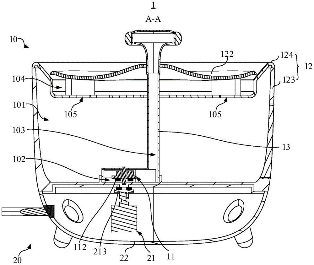
as shown in fig. 3, the main body 10 has a reservoir 101, a pump chamber 102 communicating with the reservoir 101, and a liquid supply passage 103 communicating with the pump chamber 102. The rotary member 11 is capable of pumping the liquid in the pump chamber 102 to the feeding section by rotating in the pump chamber 102. Specifically, the infusion path 103 is used to deliver the liquid pumped by the rotating member 11 to the feeding area. That is, the administration channel 103 may communicate the pumping chamber 102 and the feeding area.
As shown in fig. 3, the main body 10 may include a first housing 12 and a channel member 13.
As shown in fig. 3, the reservoir chamber 101 and the pump chamber 102 may be open to the first housing 12. Alternatively, a side of the first housing 12 away from the rotation member 11 is formed with a liquid containing space 104 away from the liquid storage chamber 101 and a communication hole 105 communicating with the liquid containing space 104. For example, the top of the first housing 12 facing away from the reservoir 101 may form a liquid containing space 104 and a communication hole 105 communicating with the liquid containing space 104. The liquid containing space 104 may communicate with the liquid storage chamber 101 through the communication hole 105. The body 10 may further include a filter (not shown). The filtering piece is used for filtering the liquid flowing into the liquid storage cavity 101 from the liquid containing space 104 through the communication hole 105, so that the water quality is improved, and the pollution is reduced. For example, the filter may be provided in the liquid containing space 104 and cover the communication hole 105. A liquid containing tray 122 spaced from the bottom of the liquid containing space 104 may be further disposed in the liquid containing space 104.
As shown in fig. 3, the channel member 13 may be opened with an infusion channel 103. The passage member 13 may be inserted in the first housing 12 and communicates with the pump liquid chamber 102.
The transfusion channel 103 penetrates into the liquid containing space 104. The infusion channel 103 can deliver liquid to the liquid holding space 104. The receiving space 104 and/or tray 122 may be considered a feeding area, or correspond to a feeding area, where a pet may drink directly from the feeding area. The liquid holding space 104 may be used for temporarily storing liquid. The liquid in the liquid containing space 104 can flow back to the liquid storage cavity 101 again. The liquid in the liquid containing space 104 can flow back to the liquid storage cavity 101 through the communication hole 105 again, so that water resource can be recycled, water resource can be saved, and the phenomenon that the liquid stays in the liquid containing space 104 for a long time to form dead water and is easily polluted can be reduced.
Further, the pump chamber 102 may be provided to be detachable and attachable, so that the rotor 11 may be exposed therein in a detached state, thereby facilitating cleaning of the rotor 11 and the pump chamber 102. As shown in fig. 3 and 4, the first housing 12 is provided with a first sub-chamber 121 within the reservoir 101. The channel member 13 may be inserted into the first housing 12 and extend into the reservoir 101. The channel piece 13 may include a channel body 131 and a second sub-cavity 132 connected to each other. The channel body 131 is provided with a transfusion channel 103. The infusion channel 103 communicates with the second subcavity 132. First subchamber 121 and second subchamber 132 are removably connected to collectively enclose pump fluid chamber 102 when connected.
Alternatively, the rotor 11 may be detachably and rotatably supported between the first sub-chamber 121 and the second sub-chamber 132, for example, between the top of the first sub-chamber 121 and the bottom of the second sub-chamber 132. Specifically, the rotational shaft 1113 of the rotational member 11 may be rotatably supported between the top of the first sub-chamber 121 and the bottom of the second sub-chamber 132.
The first sub-cavity 121 and the second sub-cavity 132 are detachably connected to realize the detachment and the combination of the pump liquid cavity 102, so that the rotating member 11 in the pump liquid cavity 102 can be exposed in a detached state, and the rotating member 11 can be cleaned conveniently. Further, the rotating member 11 is detachably supported in the pump fluid chamber 102, so that the rotating member 11 can be conveniently detached, cleaned, maintained and the like.
The first sub-chamber 121 is fixedly disposed at the bottom of the first housing 12, for example. Specifically, the bottom of the reservoir 101 enclosed by the first housing 12 is provided with an annular protrusion, which may be considered as the first sub-cavity 121, or the annular protrusion and the bottom of the first housing 12 may be considered as constituting the first sub-cavity 121.
One end of the channel body 131 far from the second sub-cavity 132 can penetrate through the liquid containing space 104 and the liquid containing tray 122, and the liquid conveying channel 103 is used for conveying liquid to the liquid containing tray 122 and the liquid containing space 104. In particular, the outlet of the infusion channel 103 may be arranged towards the drip tray 122, such that liquid flowing out through the infusion channel 103 may fall into the drip tray 122. Alternatively, the outlet of the infusion channel 103 may be located higher than the drip tray 122, above the drip tray 122. The difference in height between the outlet of the infusion channel 103 and the drip tray 122 may be such that the liquid exiting the infusion channel 103 may appear as a flowing liquid, or may be referred to as "running water", which may attract the pet to drink, and which may be more enjoyable to drink running water.
The liquid containing tray 122 may be arranged in an undulated manner. Thus, the liquid containing tray 122 has a concave portion which can be used for containing liquid, so that the liquid can be drunk by a pet. When its recess is full of liquid, drip tray 122 is positioned to allow liquid to overflow into drip space 104. For example, the recess of the drip tray 122 may be arranged shallow, e.g. with a height difference of 0.5-5cm, optionally 1-3cm, between the bottom and the outer edge of the recess. Alternatively, the tray 122 may have a convex middle part and a concave outer part, similar to a "W" shape, the convex middle part may be sleeved on the infusion channel 103, and the concave outer part is used for containing liquid. The liquid containing disc 122 and the liquid containing space 104 can form a water feeding area with a double-layer structure, so that a multi-layer water feeding space can be provided for pets, the liquidity of liquid can be improved, and the situation that the liquid overflowing from the liquid containing disc 122 directly flows out to pollute the environment is avoided.
As shown in fig. 3 and 4, the first housing 12 may include a liquid storage sub-housing 123 and a liquid containing sub-housing 124. The liquid storage sub-housing 123 may be formed with a liquid storage space. The liquid containing shell 124 covers the liquid storage shell 123 to cover the liquid storage space so as to form the liquid storage cavity 101. The first sub-chamber 121 may be disposed in the liquid storage sub-housing 123. The liquid containing sub-case 124 is formed with a liquid containing space 104 and a communication hole 105 communicating with the liquid containing space 104. The reservoir chamber 101 communicates with the reservoir chamber 101 through a communication hole 105. The liquid conveying channel 103 penetrates into the liquid containing space 104 of the liquid containing shell 124, the liquid containing plate 122 which is arranged at an interval with the bottom of the liquid containing space 104 is arranged in the liquid containing space 104 of the liquid containing shell 124, and the liquid conveying channel 103 is used for spraying liquid to the liquid containing plate 122. Alternatively, the liquid storage housing 123 and the liquid containing housing 124 may be integrally formed, or may be detachably combined, that is, the liquid storage housing 123 and the liquid containing housing 124 may be detachably connected. Of course, the drip tray 122 may not be provided.
The top of the second sub-chamber 132 may be disposed toward the bottom of the first housing 12, and the top of the second sub-chamber 132 may be opened with the liquid inlet hole 106. Liquid in the reservoir chamber 101 can enter the pump chamber 102 through the inlet aperture 106.
As shown in fig. 3, the channel body 131 may include a first channel section 1311, a second channel section 1312, and a spray cap 1313, which are connected in sequence. One end of the first channel segment 1311 connects to the second sub-cavity 132 and one end of the first channel segment 1311 connects to the second channel segment 1312. The channel diameter of the first channel segment 1311 may be constant, or may be tapered, or may remain constant after tapering, and finally remain constant. The first channel section 1311 has a channel diameter connecting one end of the second channel section 1312, for example, smaller than or equal to the channel diameter of the second channel section 1312. The channel diameter of the second channel section 1312 gradually increases in a direction away from the second channel section 1312, for example the second channel section 1312 may appear trumpet-shaped. Also, the end of the second channel section 1312 remote from the first channel section 1311 has a flat-like space. The spraying cover 1313 may cover/cover an end of the second channel 1312 far from the first channel 1311. The spray cap 1313 is, for example, a silicone member. Of course, the spray cap 1313 may be a spray head with a separate space, and the end of the second channel segment 1312 far from the first channel segment 1311 may communicate with the spray cap 1313. An outlet for liquid to flow out may be provided in the third channel segment and towards the drip tray 122. The structure of the passage member 13 described above is only one of example structures, and is not limited to this example structure.
The diameter of the channel body 131 is set as above, the diameter of the first channel section 1311 is smaller, the diameter of the second channel section 1312 is larger, and the diameter of the channel of the second channel section 1312 gradually increases, on one hand, the smaller diameter of the channel of the first channel section 1311 can increase the flow speed and the hydraulic pressure, so that the liquid can be conveyed more smoothly, the gradually increased diameter of the channel of the second channel section 1312 can moderate the flow speed of the liquid before the liquid is sprayed out, so that the sprayed liquid flow is gentler, the pet can drink the liquid conveniently, and the gradually increased diameter of the channel of the second channel section 1312 can moderate the inflow and outflow of the liquid, thereby reducing the noise.
The base 20 is described by way of example below:
as shown in fig. 2, the base 20 may include a second housing 22 and a driving member 21. The driver 21 may be disposed in the second housing 22. The second housing 22 may be used to carry the first housing 12. The bottom of the second housing 22 may be provided with support feet for supporting the base 20 to the ground. The drive 21 is a drive device based on a brushless motor, for example.
Based on the above description of the main body 10 and the base 20, the fitting structure between the main body 10 and the base 20 will be described:
as shown in fig. 5, when the main body 10 is carried on the base 20, the driving member 21 and the rotating member 11 can be aligned. Optionally, the body 10 may be provided with a first docking portion 125. The base 20 is provided with a second docking portion 221. When one side of the main body 10 is carried on one side of the base 20, the first docking portion 125 and the second docking portion 221 can be in a socket fit so that the driver 21 and the rotation member 11 can be aligned with each other.
Specifically, the first docking portion 125 may be disposed at one side of the first casing 12 carried on the base 20, that is, at the bottom of the first casing 12. The second docking portion 221 may be disposed at one side of the second case 22 for carrying the main body 10.
As shown in fig. 5, a recessed portion 126 may be formed at one side of the main body 10. Specifically, the side of the first housing 12 carried by the base 20 may be provided with a recessed area 126. The first mating portion 125 is a protrusion convexly disposed in the recessed area 126. Specifically, the first butting portion 125 is a protrusion protruding from the first housing 12 in the recessed area 126.
As shown in fig. 5, one side of the base 20 is provided with a boss portion 222. Specifically, one side of the main body 10 of the second housing 22 for carrying is provided with a boss portion 222. The shape and size of the boss portion 222 and recessed area 126 match. The second docking portion 221 is a recess formed in the boss portion 222. Specifically, the second docking portion 221 may be a recess concavely formed in the boss portion 222. The shape and size of the recesses and projections may be matched.
The first and second housings 12 and 22 may be in contact when one side of the main body 10 is carried on one side of the base 20. At this time, the boss portion 222 may be fitted in the depression 126, and the first docking portion 125, which is a protrusion, may be fitted in the second docking portion 221, which is a recess.
In this way, the boss portion 222 of the base 20 is embedded in the recessed area 126 of the main body 10, and the first docking portion 125 of the main body 10 is embedded in the second docking portion 221 of the base 20, so as to form a cross-embedded structure, so that the combined structure of the main body 10 and the base 20 is more stable, displacement is not easy to occur, and the structural stability is improved.
Moreover, the interfitting engagement of the projections and recesses enables the rotor 11 and driver 21 to be effectively aligned. Specifically, the rotating shaft 1113 of the rotating member 11 is rotatably supported by the first docking portion 125, and the driving member 21 is disposed toward the second docking portion 221, so that the rotating member 11 and the driving member 21 can be aligned when the first docking portion 125 is embedded in the second docking portion 221.
In this embodiment, the alignment of the rotating member 11 and the driving member 21 means that the two are matched in position, and then the two can be magnetically attracted effectively, so as to achieve the goal that the driving member 21 drives the rotating member 11 to rotate synchronously through magnetism.
The rotary member 11 and the driving member 21 may have magnetism. For example, the rotation member 11 may be provided with the first magnetic member 112. The driving member 21 may be provided with a second magnetic member 213, and the first magnetic member 112 and the second magnetic member 213 may be magnetically attracted. There are various cases where the rotation member 11 and the driving member 21 have magnetism, and two of them are described below by way of example.
In the first case: as shown in fig. 6, the rotation member 11 may include an impeller 111 and a first magnetic member 112. An impeller 111 may be rotatably disposed within the pump fluid chamber 102, and a first magnetic member 112 may be disposed on the impeller 111.
The impeller 111 may include a rotating seat 1111 and at least one blade 1112. At least one blade 1112 is fixedly attached to the swivel 1111. For example, the blades 1112 may be partially embedded within the swivel 1111. The number of blades 1112 may be four. The blades 1112 may be arranged in a wave-like manner. The blades 1112 may be extended from the rotation shaft 1113 of the rotation base 1111 in a radial direction of the rotation base 1111. The width direction of the blades 1112 may be the same as the axial direction of the rotating shaft 1113.
The rotary seat 1111 may be rotatably disposed within the pump chamber 102 via a rotary shaft 1113. The first magnetic member 112 may be disposed on the rotating seat 1111. Alternatively, the first magnetic member 112 may be disposed on a side of the rotating seat 1111 facing the driving member 21.
The driving member 21 may be provided with a second magnetic member 213. As shown in fig. 6, the driving member 21 may include a driving body 211, a supporting base 212, and a second magnetic member 213. The support base 212 is coupled to an output shaft of the driving body 211 to be rotatable with the output shaft. Specifically, the supporting seat 212 may be sleeved on the free end of the output shaft. The second magnetic member 213 may be disposed on the supporting base 212. Alternatively, the second magnetic element 213 may be disposed on a side of the supporting base 212 facing the rotating element 11. The driving body 211 is, for example, a brushless motor.
The first magnetic member 112 may include at least one magnet, such as two magnets. The second magnetic member 213 may include at least one magnet, for example, two magnets. The number of magnets of the first magnetic member 112 may be the same as the number of magnets of the second magnetic member 213, and the positions correspond one to one. The magnetic poles of the magnets of the first magnetic member 112 and the corresponding magnets of the second magnetic member 213 are different, for example, the N-pole of the magnet of the first magnetic member 112 corresponds to the S-pole of the magnet of the second magnetic member 213.
As such, the first magnetic member 112 and the second magnetic member 213 can magnetically attract each other. By arranging the magnetic pole positions of the first magnetic member 112 and the second magnetic member 213, the first magnetic member 112 and the second magnetic member 213 have good attraction force, so that the driving member 21 can drive the rotating member 11 to rotate synchronously by magnetic force.
In the second case: as shown in fig. 7, with respect to the first case, it may be provided that the rotating seat 1111 and the supporting seat 212 in the first case may have magnetism themselves, for example, both may be magnetic members.
Specifically, the rotating member 11 may include at least one blade 1112 and a first magnetic member 112 a. At least one blade 1112 is fixedly disposed on the first magnetic member 112 a. The first magnetic member 112a is rotatably disposed in the pump fluid chamber 102 via a rotating shaft 1113. That is, the first magnetic member 112a in the second case can be regarded as the rotating seat 1111 provided with the magnetism in the first case, so that it is possible to eliminate the need for providing an additional magnetic member.
As shown in fig. 7, the driving member 21 may include a driving body 211 and a second magnetic member 213 a. The second magnetic member 213a may be fixedly coupled to the output shaft of the driving body 211 to be rotatable with the output shaft. That is, the second magnetic member 213a in the second case can be regarded as the support base 212 provided with the magnetic property in the first case, and thus, it is not necessary to provide an additional magnetic member.
Compared to the first case, the first magnetic member 112 is provided as the rotating seat 1111, and the second magnetic member 213 is provided as the supporting seat 212, so that the structure can be simplified and the reliability of the structure can be improved.
In summary, the driving member 21 drives the rotating member 11 to rotate in a spaced magnetic attraction manner, so that the liquid flows through the rotating member 11 and does not flow through the driving member 21, water and electricity separation is realized, electrification of the liquid can be effectively avoided, risks such as electric leakage caused by arrangement of wires, electric components and the like in the liquid storage cavity 101 are reduced, and wiring complexity and structural complexity are effectively reduced.
The above description is only an example of the present application and is not intended to limit the scope of the present application, and all modifications of equivalent structures and equivalent processes, which are made by the contents of the specification and the drawings, or which are directly or indirectly applied to other related technical fields, are intended to be included within the scope of the present application.