CN216481003U - Dust fall system of incinerator - Google Patents
Dust fall system of incinerator Download PDFInfo
- Publication number
- CN216481003U CN216481003U CN202123142219.XU CN202123142219U CN216481003U CN 216481003 U CN216481003 U CN 216481003U CN 202123142219 U CN202123142219 U CN 202123142219U CN 216481003 U CN216481003 U CN 216481003U
- Authority
- CN
- China
- Prior art keywords
- spray gun
- incinerator
- lower ash
- ash channel
- storage tank
- Prior art date
- Legal status (The legal status is an assumption and is not a legal conclusion. Google has not performed a legal analysis and makes no representation as to the accuracy of the status listed.)
- Active
Links
Images

Landscapes
- Gasification And Melting Of Waste (AREA)
Abstract
本实用新型公开了一种焚烧炉的降尘系统,包括具有炉膛的焚烧炉本体,还包括喷枪组件、存液池和控制器,其中在所述焚烧炉本体上设置有下灰通道且所述下灰通道与所述炉膛相连通,所述喷枪组件一端与所述下灰通道相连通,另一端与所述存液池相连通,所述控制器与所述喷枪组件电性连接以控制所述喷枪组件将所述存液池内的液体往所述下灰通道内喷出,进入所述下灰通道内的液体继续往所述炉膛内流动以对所述炉膛内进行降尘降温工作。其结构简单,有效解决焚烧炉下灰时所产生扬尘问题,同时有效对焚烧炉进行降温工作。
The utility model discloses a dust suppression system for an incinerator, which comprises an incinerator body with a furnace chamber, a spray gun assembly, a liquid storage tank and a controller, wherein a lower ash channel is arranged on the incinerator body and the lower The ash channel is communicated with the furnace, one end of the spray gun assembly is communicated with the lower ash channel, and the other end is communicated with the liquid storage tank, and the controller is electrically connected with the spray gun assembly to control the The spray gun assembly sprays the liquid in the liquid storage tank into the lower ash channel, and the liquid entering the lower ash channel continues to flow into the furnace to reduce dust and temperature in the furnace. It has a simple structure, effectively solves the problem of fugitive dust generated when the incinerator is put down ashes, and at the same time effectively cools the incinerator.
Description
技术领域technical field
本实用新型涉及垃圾焚烧炉技术领域,尤其涉及一种焚烧炉的降尘系统。The utility model relates to the technical field of garbage incinerators, in particular to a dust suppression system of an incinerator.
背景技术Background technique
垃圾焚烧发电厂焚烧炉作为垃圾焚烧发电厂主要设备,相关技术中,大多数情况下,垃圾在焚烧炉内燃烧情况主要通过火焰监视器或者现场观火孔观察,而焚烧炉二三通道下灰溜槽布置在焚烧炉后拱中部或后拱侧墙,焚烧炉二三通道下灰时产生扬尘在焚烧炉燃尽区域,导致火焰监视器和现场观火孔积灰,使运行操作人员无法准确判断垃圾在焚烧炉内燃烧情况。Waste incineration power plant The incinerator is the main equipment of the waste incineration power plant. In related technologies, in most cases, the combustion of waste in the incinerator is mainly observed through the flame monitor or the on-site fire observation hole, while the ash in the second and third passages of the incinerator is observed. The chute is arranged in the middle of the rear arch of the incinerator or on the side wall of the rear arch. When the ash in the second and third passages of the incinerator is discharged, dust will be generated in the burnout area of the incinerator, resulting in the accumulation of ash in the flame monitor and the on-site fire observation hole, which makes the operation operator unable to accurately judge. Garbage burning in an incinerator.
发明内容SUMMARY OF THE INVENTION
本实用新型旨在至少在一定程度上解决现有相关技术中存在的问题之一,为此,本实用新型提出一种焚烧炉的降尘系统,其结构简单,有效解决焚烧炉下灰时所产生扬尘问题,同时有效对焚烧炉进行降温工作。The utility model aims to solve one of the problems existing in the related art at least to a certain extent. For this reason, the utility model proposes a dust suppression system for an incinerator, which has a simple structure and can effectively solve the problems caused by the incinerator when the ash is lowered. At the same time, it can effectively cool the incinerator.
上述目的是通过如下技术方案来实现的:The above purpose is achieved through the following technical solutions:
一种焚烧炉的降尘系统,包括具有炉膛的焚烧炉本体,还包括喷枪组件、存液池和控制器,其中在所述焚烧炉本体上设置有下灰通道且所述下灰通道与所述炉膛相连通,所述喷枪组件一端与所述下灰通道相连通,另一端与所述存液池相连通,所述控制器与所述喷枪组件电性连接以控制所述喷枪组件将所述存液池内的液体往所述下灰通道内喷出,进入所述下灰通道内的液体继续往所述炉膛内流动以对所述炉膛内进行降尘降温工作。A dust suppression system for an incinerator, comprising an incinerator body with a furnace chamber, a spray gun assembly, a liquid storage tank and a controller, wherein a lower ash channel is provided on the incinerator body, and the lower ash channel and the The furnace is communicated, one end of the spray gun assembly is communicated with the lower ash channel, and the other end is communicated with the liquid storage tank, and the controller is electrically connected with the spray gun assembly to control the spray gun assembly to The liquid in the liquid storage tank is sprayed into the lower ash channel, and the liquid entering the lower ash channel continues to flow into the furnace to reduce dust and temperature in the furnace.
在一些实施方式中,所述喷枪组件包括连接管、水泵和喷枪,其中所述连接管一端与与所述存液池相连通,另一端与所述下灰通道相连通,所述水泵设置在所述连接管上,所述喷枪设置于所述连接管在接近于所述下灰通道的一端且所述喷枪位于所述下灰通道内,所述水泵、所述喷枪分别与所述控制器电性连接。In some embodiments, the spray gun assembly includes a connecting pipe, a water pump and a spray gun, wherein one end of the connecting pipe is communicated with the liquid storage tank, and the other end is communicated with the lower ash channel, and the water pump is arranged at On the connecting pipe, the spray gun is arranged at one end of the connecting pipe close to the lower ash channel and the spray gun is located in the lower ash channel, the water pump and the spray gun are respectively connected to the controller. Electrical connection.
在一些实施方式中,所述喷枪组件还包括与所述控制器电性连接的调节阀,所述调节阀设置在所述连接管且位于所述喷枪与所述水泵的之间位置处。In some embodiments, the spray gun assembly further includes a regulating valve electrically connected to the controller, the regulating valve is disposed on the connecting pipe and is located between the spray gun and the water pump.
在一些实施方式中,所述喷枪组件还包括压缩空气管,所述压缩空气管设置在所述喷枪上。In some embodiments, the spray gun assembly further includes a compressed air tube disposed on the spray gun.
在一些实施方式中,所述喷枪为雾化式喷枪制成。In some embodiments, the spray gun is made of an atomizing spray gun.
在一些实施方式中,还包括渗滤液处理设备,所述渗滤液处理设备的出液端与所述存液池相连通以使所述存液池适于存储所述渗滤液处理设备所产生的浓缩液。In some embodiments, a leachate treatment device is further included, the liquid outlet of the leachate treatment device is in communication with the liquid storage tank, so that the liquid storage tank is suitable for storing the leachate treatment device produced by the leachate treatment device. Concentrate.
在一些实施方式中,所述下灰通道设置在所述焚烧炉本体的后拱位置处。In some embodiments, the lower ash channel is provided at the rear arch position of the incinerator body.
与现有技术相比,本实用新型的至少包括以下有益效果:Compared with the prior art, the utility model at least includes the following beneficial effects:
1.本实用新型的焚烧炉的降尘系统,其结构简单,有效解决焚烧炉下灰时所产生扬尘问题,同时有效对焚烧炉进行降温工作。1. The dust suppression system of the incinerator of the present utility model has a simple structure, effectively solves the problem of fugitive dust generated when the incinerator is put down ashes, and effectively cools the incinerator at the same time.
附图说明Description of drawings
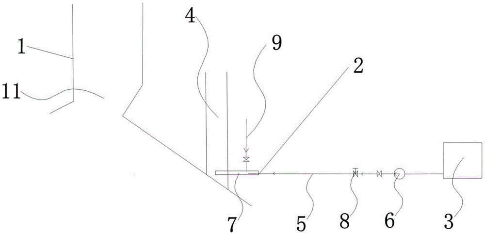
图1是本实用新型实施例中焚烧炉的降尘系统的结构示意图。1 is a schematic structural diagram of a dust suppression system of an incinerator in an embodiment of the present invention.
具体实施方式Detailed ways
为了使本技术领域的人员更好地理解本实用新型方案,下面将结合本实用新型实施例中的附图,对本实用新型实施例中的技术方案进行清楚、完整地描述,显然,所描述的实施例仅仅是本实用新型一部分的实施例,而不是全部的实施例。基于本实用新型中的实施例,本领域普通技术人员在没有做出创造性劳动前提下所获得的所有其他实施例,都应当属于本实用新型请求保护的技术方案范围。In order to enable those skilled in the art to better understand the solutions of the present invention, the technical solutions in the embodiments of the present invention will be clearly and completely described below with reference to the accompanying drawings in the embodiments of the present invention. Obviously, the described The embodiments are only some of the embodiments of the present invention, but not all of the embodiments. Based on the embodiments of the present invention, all other embodiments obtained by persons of ordinary skill in the art without creative work shall fall within the scope of the technical solutions claimed in the present invention.
实施例一:Example 1:
如图1所示,本实施例提供一种焚烧炉的降尘系统,包括具有炉膛11的焚烧炉本体1,还包括喷枪组件2、存液池3和控制器,其中在焚烧炉本体1上设置有下灰通道4且下灰通道4与炉膛11相连通,喷枪组件2一端与下灰通道4相连通,另一端与存液池3相连通,控制器与喷枪组件2电性连接以控制喷枪组件2将存液池3内的液体往下灰通道4内喷出,进入下灰通道4内的液体继续往炉膛11内流动以对炉膛11内进行降尘降温工作。As shown in FIG. 1 , the present embodiment provides a dust suppression system for an incinerator, including an
在本实施例中,由于焚烧炉二三通道下灰时在焚烧炉燃尽区域会产生扬尘,从而导致火焰监视器和现场观火孔积灰,进而使运行操作人员无法准确判断垃圾在焚烧炉内的燃烧情况,因此控制器控制喷枪组件2将存液池3内的液体往下灰通道4内喷出,进入下灰通道4内的液体继续往炉膛11内流动以对炉膛11内进行降尘降温工作,其结构简单,有效解决焚烧炉下灰时所产生扬尘问题,同时有效对焚烧炉进行降温工作。In this embodiment, since dust is generated in the burnout area of the incinerator when the second and third passages of the incinerator are discharged, dust will accumulate in the flame monitor and the on-site fire observation hole, so that the operator cannot accurately judge whether the garbage is in the incinerator. Therefore, the controller controls the
进一步地,喷枪组件2包括连接管5、水泵6和喷枪7,其中连接管5一端与与存液池3相连通,另一端与下灰通道4相连通,水泵6设置在连接管5上,喷枪7设置于连接管5在接近于下灰通道4的一端且喷枪7位于下灰通道4内,水泵6、喷枪7分别与控制器电性连接,其结构简单,设计合理,可利于将存液池3内的液体往下灰通道4内喷出。Further, the
优选地,喷枪组件2还包括与控制器电性连接的调节阀8,调节阀8设置在连接管5且位于喷枪7与水泵6的之间位置处,其结构简单,可利于对连接管5内所流经的液体流量进行调节控制。Preferably, the
具体地,喷枪组件2还包括压缩空气管9,压缩空气管9设置在喷枪7上,其设计合理、巧妙,可进一步提高喷枪7往下灰通道4内喷出液体的压力。Specifically, the
优选地,喷枪7为雾化式喷枪制成,其设计合理,可有效提高炉膛11内的降尘和降温效果。Preferably, the
进一步地,还包括渗滤液处理设备,渗滤液处理设备的出液端与存液池3相连通以使存液池3适于存储渗滤液处理设备所产生的浓缩液,其结构简单,设计合理,可利于对渗滤液处理设备所产生的浓缩液进行回收处理。Further, it also includes leachate treatment equipment, the liquid outlet end of the leachate treatment equipment is communicated with the
特别地,下灰通道4设置在焚烧炉本体1的后拱位置处,其设计合理,可有效提高炉膛11内的降尘效果。In particular, the
在本实施例中,下灰通道4设置在焚烧炉本体1的后拱位置处,尤其是优选设置在焚烧炉本体1的后拱中部位置处或者后拱侧墙上,存液池3的进口与渗滤液处理设备的出液端和/或外部供水相连通,当然,更优地,本实施例中存液池3的进口以与渗滤液处理设备的出液端相连通举例进行描述,其它类型的不再赘述,如此即可有效对垃圾焚烧发电厂所产生的浓缩液进行处理,存液池3的出口通过连接管5与喷枪7相连通,喷枪7的喷嘴位于下灰通道4与炉膛11后拱的相交位置处,在连接管5上由存液池3往喷枪7的方向依次设置有水泵6和调节阀8,水泵6适于将存液池3内的浓缩液泵送至下灰通道4内,调节阀8适于对连接管5的通断进行控制以及通过调节阀8门的开度对连接管5内所流经的液体流量进行调节控制,本实施例中喷枪7优选为雾化式喷枪制成,从而有效提高炉膛11内的降尘和降温效果,当焚烧炉二三通道下灰时在焚烧炉燃尽区域产生扬尘,控制器控制调节阀8打开以使存液池3通过连接管5与喷枪7相互连通,然后同时打开水泵6和喷枪7,水泵6将存液池3内的浓缩液经连接管5泵送至喷枪7上,通过喷枪7对浓缩液进行雾化后再喷射至下灰通道4内,进入下灰通道4内的浓缩液继续往炉膛11内流动,以对炉膛11内进行降尘降温工作,从而有效解决焚烧炉二三通道下灰时在焚烧炉燃尽区域所产生的扬尘问题,由于喷枪7的喷嘴位于下灰通道4与炉膛11后拱的相交位置处,如此即可使喷枪7将雾化后的浓缩液直接往炉膛11内喷出,从而进一步提高降尘和降温的效果。In this embodiment, the
以上所述的仅是本实用新型的一些实施方式。对于本领域的普通技术人员来说,在不脱离本实用新型创造构思的前提下,还可以做出若干变形和改进,这些都属于本实用新型的保护范围。The above are only some embodiments of the present invention. For those of ordinary skill in the art, without departing from the inventive concept of the present invention, several modifications and improvements can be made, which all belong to the protection scope of the present invention.
Claims (7)
Priority Applications (1)
| Application Number | Priority Date | Filing Date | Title |
|---|---|---|---|
| CN202123142219.XU CN216481003U (en) | 2021-12-14 | 2021-12-14 | Dust fall system of incinerator |
Applications Claiming Priority (1)
| Application Number | Priority Date | Filing Date | Title |
|---|---|---|---|
| CN202123142219.XU CN216481003U (en) | 2021-12-14 | 2021-12-14 | Dust fall system of incinerator |
Publications (1)
| Publication Number | Publication Date |
|---|---|
| CN216481003U true CN216481003U (en) | 2022-05-10 |
Family
ID=81424474
Family Applications (1)
| Application Number | Title | Priority Date | Filing Date |
|---|---|---|---|
| CN202123142219.XU Active CN216481003U (en) | 2021-12-14 | 2021-12-14 | Dust fall system of incinerator |
Country Status (1)
| Country | Link |
|---|---|
| CN (1) | CN216481003U (en) |
-
2021
- 2021-12-14 CN CN202123142219.XU patent/CN216481003U/en active Active
Similar Documents
| Publication | Publication Date | Title |
|---|---|---|
| CN216481003U (en) | Dust fall system of incinerator | |
| CN201410434Y (en) | Steady Combustion Large Fog Machine | |
| CN103185340A (en) | Anti-tar-blocking nozzle system and nozzle tar treatment method adopting same | |
| CN209836219U (en) | Converter fire door spraying dust suppression device | |
| CN208966380U (en) | Prevent the safe voltage-stabilizing system of steam-turbine lubrication oil pump pneumatosis starting failure | |
| CN217612608U (en) | A recyclable sprinkler system for electrochemical energy storage devices | |
| CN104115808A (en) | Ignition system for smoke sprayers | |
| CN209189980U (en) | A kind of micro- mist continuous casting billet flame cutting dust pelletizing system of full-automatic high-pressure | |
| CN209501160U (en) | Spraying dust suppression and cooling device for coke oven greenhouse | |
| CN207478277U (en) | The system of CO in a kind of removing flue gas | |
| CN110918283B (en) | A real-time pressure control system for low-pressure two-fluid water mist nozzles | |
| CN211119445U (en) | Biomass boiler flue gas processing apparatus | |
| CN202757136U (en) | Boiler water soot blower gun barrel structure | |
| CN101622433A (en) | Blast furnace gas burning facility and its operation method | |
| CN2531249Y (en) | High-efficiency energy-saving burner for heat gas in producer | |
| CN211158320U (en) | High-pressure water mist fire extinguishing device | |
| CN106869514B (en) | Haze spraying, cleaning and fire-fighting jet device for building attachment | |
| CN206103578U (en) | Half -dried quench tower atomizing water flow control system | |
| CN112402831A (en) | A kind of inhibitor spraying device for coal seam fire extinguishing | |
| CN206320776U (en) | A kind of biomass boiler system with denitrification apparatus | |
| CN217187632U (en) | A new type of gas automatic fire extinguishing device | |
| CN221181481U (en) | Fire extinguisher spray gun and fire extinguisher | |
| CN216047737U (en) | Accurately-adjusted atomizing spray gun | |
| CN217843975U (en) | Gas-jet stove combustion system | |
| CN1314923C (en) | A water-assisted combustion energy-saving device for gas appliances or gas-powered engines |
Legal Events
| Date | Code | Title | Description |
|---|---|---|---|
| GR01 | Patent grant | ||
| GR01 | Patent grant | ||
| CP03 | Change of name, title or address | ||
| CP03 | Change of name, title or address |
Address after: 528400 beside wuzhu mountain, Huangpu town, Zhongshan City, Guangdong Province Patentee after: Zhongshan North Public Environmental Protection Energy Co.,Ltd. Country or region after: China Address before: 528400 beside wuzhu mountain, Huangpu town, Zhongshan City, Guangdong Province Patentee before: ZHONGSHAN TIANYI ENERGY Co.,Ltd. Country or region before: China |