CN216318105U - Installation extractor of planting baffle guide ring - Google Patents
Installation extractor of planting baffle guide ring Download PDFInfo
- Publication number
- CN216318105U CN216318105U CN202120479152.XU CN202120479152U CN216318105U CN 216318105 U CN216318105 U CN 216318105U CN 202120479152 U CN202120479152 U CN 202120479152U CN 216318105 U CN216318105 U CN 216318105U
- Authority
- CN
- China
- Prior art keywords
- section
- locking
- guide ring
- main handle
- head
- Prior art date
- Legal status (The legal status is an assumption and is not a legal conclusion. Google has not performed a legal analysis and makes no representation as to the accuracy of the status listed.)
- Active
Links
Images


Landscapes
- Prostheses (AREA)
Abstract
The utility model belongs to the field of an oral implantation navigation process, and discloses an installation extractor for an implantation guide plate guide ring. This plant installation extractor of baffle guide ring, including replacing head and main handle, can replace the head including installation section, thrust section and guide ring fixed section, the main handle is including gripping section, locking function section and lock sleeve, can replace the installation section of head and install in the locking function section of main handle, and locking section and the unblock section through locking piece cooperation lock sleeve realize to the locking and the unblock of replacing the head. Utilize this installation extractor combination, various guide rings are taken out in the installation that can be effective quick to can realize the quick replacement of head, match the guide ring of different models, reduce the whole volume of a whole set of instrument, convenient storage and use, and effective reduce cost.
Description
Technical Field
The utility model belongs to the field of an oral implantation navigation process, and particularly relates to an installation extractor for an implantation guide plate guide ring.
Background
Dentition defects are common problems in the field of oral repair, can cause the chewing function of a patient to be limited, has influence on the face and beauty of the patient, and can also influence the pronunciation of the patient due to the tooth missing in a special area. Long-term dentition defects can lead to problems of tilting of the remaining teeth on the gap side, stretching of the teeth in the jaw, food retention, etc., which in turn can lead to caries or (and) periodontal disease of the remaining teeth, and also can lead to temporomandibular joint disease, which in turn can affect the entire oromandibular system. Therefore, patients with dentition defects should be treated in a timely manner.
Implant repair is one of the most effective repair methods for treating dentition defects at present. In the case of row implant restoration, a prepared hole is made in the alveolar bone by an implant operation, and then the implant is substituted for the missing natural tooth root. In order to make the operation more accurate, generally will adopt the planting baffle to navigate. The planting guide plate is provided with a metal planting guide ring so as to accurately control the direction and the depth of the drill point.
In the prior art, the guide rings are all circular rings, and after the resin guide plate is manufactured, the guide rings are required to be manually inserted into corresponding holes of the resin guide plate. The guide ring is inserted into the guide plate generally by hands and is not easy to operate. When the guide plate is loose, the guide plate is not easy to fix accurately, so that the direction of the guide ring is easy to change, and the planting precision is influenced; when the guide plate is biased tightly, the guide plate is not easy to be inserted, and is not easy to be taken out and replaced after being inserted, so that the working efficiency of a technician is low.
The patent application with the publication number of CN211884099U discloses a positioning device for manufacturing an oral implant guide plate, which comprises a guide pillar and a guide ring, wherein the guide pillar is composed of a large section and a small section of coaxial cylinders, the diameter of the small end is 0.5-1mm, the large section and the small section are connected through a conical surface, the diameter of the large section is 2-3mm, the inner diameter of the guide ring is in transition fit with the outer diameter of the large section of the guide pillar, the outer diameter of the guide ring is 4.5-5.5mm, the length of the guide ring is 6-8mm, and the guide ring is sleeved on the large section of the guide pillar. The positioning device is mainly used for positioning the guide ring when the light curing is used for manufacturing the planting guide plate, so that the planting guide plate with the guide ring is manufactured, and the accuracy of the positioning device is greatly superior to that of free-hand planting. If be used as the guide ring installation extractor after planting the baffle preparation with positioner, can improve the installation effectiveness of guide ring to a certain extent, however, need set up corresponding handheld portion when the installation, so as to grip the operation, probably need the guide ring of different diameters to the planting baffle of difference, the guide ring installation extractor of different diameters is required to the correspondence, and if make corresponding complete installation extractor respectively to the guide ring of every model, then can lead to the quantity of installing the extractor too much, occupation space is great, be unfavorable for accomodating and using.
SUMMERY OF THE UTILITY MODEL
The utility model aims to solve the technical problem of providing an installation extractor of a guide ring of a planting guide plate, which can be used for replacing the head part and adapting to guide rings of different types.
The utility model discloses an installation extractor of a guide ring of a planting guide plate, which comprises a replaceable head part and a main handle;
the replaceable head comprises an installation section, a thrust section and a guide ring fixing section, the diameter of the guide ring fixing section is matched with the inner diameter of the corresponding guide ring, the diameter of the thrust section is larger than that of the guide ring fixing section, and the installation section of the replaceable head is provided with a locking groove;
the main handle comprises a holding section and a locking functional section, the locking functional section is provided with a head mounting hole matched with the mounting section of the replaceable head, the locking functional section is provided with a locking hole penetrating through the side wall and communicated with the head mounting hole, a locking piece movably matched along the radial direction is arranged in the locking hole, and the inner end part of the locking piece is matched with a locking groove of the replaceable head;
the main handle is further provided with a lock sleeve, the lock sleeve is provided with a sleeving hole, the locking section of the main handle is movably sleeved in the sleeving hole in a penetrating mode, the sleeving hole comprises a locking section and an unlocking section, the inner diameter of the unlocking section is larger than that of the locking section, the inner wall of the locking section is used for limiting the locking piece to enable the inner end portion of the locking piece to protrude into the head mounting hole, a gap is formed between the outer sides of the unlocking section and the locking function section to enable the inner end portion of the locking piece to retract into the locking hole,
preferably, the locking function section is provided with an elastic member for pushing the unlocking section corresponding locking member of the lock sleeve to the locking section corresponding locking member.
Preferably, the sleeving hole of the lock sleeve further comprises a guide sleeve section, the locking section and the unlocking section are sequentially arranged from inside to outside, a sliding section is arranged between the holding section and the locking functional section of the main handle, and the inner end of the guide sleeve section of the lock sleeve is in sliding guide fit with the sliding section of the main handle;
the elastic piece is a spring, the spring is sleeved outside the locking function section of the main handle and is positioned in the guide sleeve section of the lock sleeve, one end of the spring abuts against the end part of the sliding section of the main handle, the other end of the spring abuts against the end part of the guide sleeve section of the lock sleeve, and a first limiting structure used for preventing the lock sleeve from sliding out of the locking function section is further arranged at the outer end part of the locking function section of the main handle.
Preferably, an annular mounting groove is formed in the outer end portion of the main handle locking function section, the first limiting structure is a ring-shaped member and is mounted in the annular mounting groove, and the outer diameter of the first limiting structure is larger than the inner diameter of the locking section of the lock sleeve.
Preferably, a second limit structure for preventing the locking piece from being exposed out of the lock sleeve due to excessive sliding of the lock sleeve is arranged between the holding section and the sliding section of the main handle.
Preferably, the second limiting structure is an annular convex structure, and the outer diameter of the second limiting structure is larger than the inner diameter of the guide sleeve section of the lock sleeve.
Preferably, an end of the locking hole near the head mounting hole has an inward projection structure that prevents the locking piece from sliding into the head mounting hole.
Preferably, the locking element is spherical.
Preferably, the mounting section of the replaceable head and the head mounting hole of the main handle are both in a non-revolving body shape, and the locking groove of the replaceable head is an annular groove arranged around the periphery of the replaceable head.
Preferably, the two side edges of the locking groove are smooth cambered surfaces or inclined surfaces.
Preferably, the holding section of the main handle comprises a hand-pushing assisting area, a first finger holding area, a blocking area and a second holding area in sequence, the diameter of the blocking area is larger than that of the first holding area and that of the second holding area, the blocking area is in smooth transition with the first finger holding area and the second holding area, and the second holding area is located at one end close to the locking functional section.
The utility model has the beneficial effects that:
(1) by utilizing the installation extractor combination, various guide rings can be effectively and quickly installed and extracted, and the labor and material cost can be saved.
(2) When the guide ring is installed by utilizing the installation extractor, the position of the installation guide ring can be more accurate by controlling the direction of the installation extractor, and the guide plate is not easy to be damaged, so that the accuracy of the guide plate is improved.
(3) The installation extractor is safer than bare-handed installation and cannot hurt a maker.
(4) The guide ring can be conveniently taken out by installing the extractor, the utilization rate is improved, and the material waste is reduced.
(5) When the guide ring has defects or the model is not required to be replaced, the guide ring can be conveniently taken out by installing the extractor, the guide plate cannot be damaged, and the waste is reduced while the piece outlet efficiency is improved.
(6) Can replace head and main handle locking cooperation, can realize the quick replacement of head, match the guide ring of different models, reduce the whole volume of a whole set of instrument, convenient storage and use to effective reduce cost.
Drawings
FIGS. 1A-1F are schematic views of various models of an alternative header;
FIG. 2 is a schematic view of an alternative head;
FIG. 3 is a schematic view of the main handle with the lock sleeve not installed;
FIG. 4 is a schematic view of a locked state of the main handle with an alternative head;
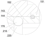
fig. 5 is an enlarged view of a portion I in fig. 4.
FIG. 6 is a schematic view of the unlocked state of the main handle and the alternative head;
reference numerals: a main handle 100, a hand-push assisting area 111, a first finger-grip area 112, a blocking area 113, a second grip area 114, a second limiting structure 120, a sliding section 130, a locking function section 140, a head mounting hole 141, a first limiting structure 142, a locking hole 143, an inward convex structure 144, an annular mounting groove 145, a lock sleeve 150, an unlocking section 151, a locking section 152, a guide sleeve section 153, a spring 160, a locking member 170, a replaceable head 200, a mounting section 210, a locking groove 220, a thrust section 230, a guide ring fixing section 240,
Detailed Description
The utility model is further described below with reference to the accompanying drawings.
The installation extractor of the guide ring of the planting guide of the utility model comprises an alternative head part 200 and a main handle 100,
as shown in fig. 2, the replaceable head 200 includes a mounting section 210, a thrust section 230 and a guide ring fixing section 240, the guide ring fixing section 240 has a diameter adapted to an inner diameter of a corresponding guide ring, the thrust section 230 has a diameter greater than that of the guide ring fixing section 240, and the mounting section 210 of the replaceable head 200 is provided with a locking groove 220;
as shown in fig. 3, the main handle 100 includes a holding section and a locking functional section 140, the locking functional section 140 is provided with a head mounting hole 141 adapted to the mounting section 210 of the replaceable head 200, the locking functional section 140 is provided with a locking hole 143 penetrating through the sidewall and communicating with the head mounting hole 141, a locking piece 170 movably engaged in the radial direction is provided in the locking hole 143, an inner end portion of the locking piece 170 is adapted to the locking groove 220 of the replaceable head 200, that is, an end of the locking piece 170 facing the head mounting hole 141 can be locked in the locking groove 220;
the main handle 100 is further provided with a lock sleeve 150, the lock sleeve 150 is provided with a sleeve hole, the locking section 152 of the main handle 100 is movably sleeved in the sleeve hole, the sleeve hole comprises a locking section 152 and an unlocking section 151, the inner diameter of the unlocking section 151 is larger than that of the locking section 152, the inner wall of the locking section 152 is used for limiting the locking piece 170 to enable the inner end portion of the locking piece 170 to protrude out of the head mounting hole 141, and a gap is formed between the outer sides of the unlocking section 151 and the locking function section 140 to enable the inner end portion of the locking piece 170 to retract into the locking hole 143.
A main handle 100 and a plurality of interchangeable heads 200 are typically provided in a set of installation extractors, with different interchangeable heads 200 having different types of guide ring retaining segments 240 to accommodate different types of guide rings. According to the inner diameter of the guide ring commonly used in the current medical market, the common sizes of the special definitions are 6, which are respectively: phi 1.5mm, phi 2.0mm, phi 3.7mm, phi 5.0mm, phi 5.1mm, and phi 6.0mm, as shown in FIG. 1A-FIG. 1F.
When the replaceable head 200 is installed, according to the inner diameter of the guide ring to be installed, the corresponding replaceable head 200 is selected, the lock sleeve 150 is pushed, the unlocking section 151 corresponds to the locking hole 143, the main handle 100 is in the unlocked state, the inner end portion of the locking member 170 can be retracted from the head mounting hole 141 into the locking hole 143, then the mounting section 210 of the replaceable head 200 is inserted into the head mounting hole 141 of the main handle 100, the locking member 170 is opposite to the locking groove 220 of the replaceable head 200, the lock sleeve 150 is pushed reversely, the locking section 152 is opposite to the locking hole 143, the main handle 100 is in the locked state, the inner end portion of the locking member 170 protrudes out of the head mounting hole 141 and is clamped into the locking groove 220 of the replaceable head 200, and the locked state is maintained, so that the replaceable head 200 is fixed on the main handle 100, as shown in fig. 4 and 5.
When the replaceable head 200 is removed, the locking sleeve 150 is pushed or pulled by force to the unlocked state, and the inner end portion of the locking member 170 can be retracted from the head mounting hole 141 into the locking hole 143, and the replaceable head 200 can be removed by slightly pulling the replaceable head 200 by force. Specifically, the locking element 170 may be forced to retract by shaking or the like, but the edges of the locking slot 220 are preferably smooth arcs or chamfers, such that pulling on the interchangeable head 200, the smooth arcs apply a force to the locking element 170 to retract the locking element 170 into an unlocked state, and the interchangeable head 200 may then be removed and installed, as shown in fig. 6.
Further, although the locking groove 220 may have a circular groove hole structure, it is determined that it is more effective to form a circumferential groove around the outer circumference of the replaceable head portion 200, and thus it is not necessary to pay attention to whether the locking groove 220 and the locking member 170 are positioned right opposite to each other when the replaceable head portion 200 is installed. However, the circumferential groove is easy to rotate the interchangeable head 200, which is not good for stable operation, and thus the mounting section 210 of the interchangeable head 200 and the head mounting hole 141 of the main handle 100 are preferably both in a non-rotational body shape, such as a hexagonal, tetragonal, or elliptical cylinder structure, which prevents the interchangeable head from rotating.
When the installation extractor is used for installing the guide ring, the guide ring is sleeved on the guide ring fixing section 240 of the replaceable head 200, limited by the thrust section 230, stopped at the end part of the thrust section 230, aligned with the guide ring installation hole of the guide plate, vertically pushed into the guide ring arrangement hole until the guide ring is in place when observed from the other side, and finally pulled out to install the extractor, so that the installation is completed.
When the guide ring is taken out, the guide ring fixing section 240 for installing the extractor is inserted into the guide ring from the reverse surface of the guide ring installation, so that the thrust section 230 just abuts against the end surface of the guide ring, and the guide ring installer is pushed forcibly, so that the guide ring can be pushed out of the installation hole of the guide plate, and the guide ring is taken out.
After the replaceable head 200 is installed, the main handle 100 needs to be kept in a locked state, specifically, a fixing structure such as a screw may be used to fix the position of the lock sleeve 150, and a mode of increasing the sliding resistance may also be used to ensure that the lock sleeve 150 does not move. However, it is preferable that the locking function section 140 is provided with an elastic member for pushing the unlocking section 151 of the lock sleeve 150 corresponding to the locking member 170 to the locking section 152 corresponding to the locking member 170, and the lock sleeve 150 can automatically slide from the unlocked state to the locked state by the elastic force of the elastic member, thereby implementing the self-locking function.
The elastic member may specifically adopt a spring 160, a spring plate, and the like, in a preferred embodiment of the present application, the sheathing hole of the lock sleeve 150 further includes a guide sleeve section 153, the locking section 152, and the unlocking section 151 are sequentially arranged from inside to outside, a sliding section 130 is provided between the holding section and the locking function section 140 of the main handle 100, and the inner end of the guide sleeve section 153 of the lock sleeve 150 is in sliding guide fit with the sliding section 130 of the main handle 100;
as shown in fig. 4 and 6, the elastic member is a spring 160, the spring 160 is sleeved outside the locking function section 140 of the main handle 100 and is located inside the guide sleeve section 153 of the lock sleeve 150, one end of the spring 160 abuts against the end of the sliding section 130 of the main handle 100, the other end abuts against the end of the guide sleeve section 153 of the lock sleeve 150, and the outer end of the locking function section 140 of the main handle 100 is further provided with a first limiting structure 142 for preventing the lock sleeve 150 from sliding out of the locking function section 140.
The guide sleeve section 153 plays a role in accommodating the spring 160, and can be matched with the sliding section 130 to play a guide role, so that the sliding stability of the lock sleeve 150 is improved, two ends of the spring 160 are respectively abutted against the main handle 100 and the lock sleeve 150, so that the lock sleeve 150 can be always in a locking state under a natural condition, and the first limiting structure 142 can limit one end of the lock sleeve 150 and prevent the lock sleeve from sliding out of the main handle 100. The first limit structure 142 may be a protrusion, a screw, a bolt, etc., and in the embodiment shown in fig. 3, 4 and 6, the outer end of the locking functional section 140 of the main handle 100 is provided with an annular mounting groove 145, the first limit structure 142 is an annular member and is mounted in the annular mounting groove 145, and the outer diameter of the first limit structure 142 is greater than the inner diameter of the locking section 152 of the lock sleeve 150. When the main handle 100 is assembled, the locking member 170 is disposed in the locking hole 143 of the locking functional section 140 of the main handle 100; then the spring 160 is sleeved into the locking function section 140 of the main handle 100 and pushed into the limit position at the end part of the sliding section 130; then the lock sleeve 150 is sleeved into the main handle 100 and is forcibly pressed into the sliding section 130; at this time, the annular mounting groove 145 for mounting the first limiting structure 142 on the main handle 100 is exposed, the annular first limiting structure 142 is sleeved into the annular mounting groove 145 and pressed in place, the lock sleeve 150 is loosened, the lock sleeve 150 pushes the lock sleeve 150 back to the first limiting structure 142 under the action of the spring 160 and cannot be dislocated, and the first limiting structure 142 may specifically adopt an annular steel wire, an annular collar and the like.
The first position-limiting structure 142 can prevent the lock sleeve 150 from sliding out of the locking function section 140, and in order to prevent the lock sleeve 150 from sliding excessively to expose the locking member 170 out of the lock sleeve 150, the second position-limiting structure 120 is provided between the grip section and the sliding section 130 of the main handle 100, and the second key position structure can also adopt a protrusion, a screw position-limiting mode and the like, in the embodiment shown in fig. 4, the second position-limiting structure 120 is an annular protrusion structure, and the outer diameter of the second position-limiting structure 120 is larger than the inner diameter of the guide sleeve section 153 of the lock sleeve 150.
The locking member 170 may be cylindrical, spherical, ellipsoidal, etc., wherein the spherical shape is most effective and the spherical shape can roll to facilitate the pulling of the replaceable head 200 out of the head mounting hole 141. To prevent the locking member 170 from sliding into the head mounting hole 141, as shown in fig. 5, the locking hole 143 has an inward protrusion 144 at an end thereof adjacent to the head mounting hole 141, and the inward protrusion 144 allows the locking member 170 to partially protrude into the head mounting hole 141 while preventing the locking member from falling inward.
As shown in fig. 3, the grip section of the main handle 100 includes a hand-push assisting area 111, a first finger grip area 112, a blocking area 113, and a second grip area 114 in sequence, the diameter of the blocking area 113 is greater than the diameters of the first grip area and the second grip area 114, the blocking area 113 is in smooth transition with the first finger grip area 112 and the second grip area 114, and the second grip area 114 is located at an end close to the locking function section 140. When the hand-push assisting area 111 is held for pushing force, the guide ring can be pushed into or pushed out of the guide plate more easily and comfortably, the first finger holding area 112 can be used for holding the little finger and the ring finger, the second holding area 114 can be used for holding the middle finger, the index finger and the thumb, and the blocking area 113 has certain blocking performance between the middle finger and the ring finger, so that the holding of the hand is more stable.
Claims (11)
1. The device for installing and extracting the guide ring of the planting guide plate is characterized by comprising an interchangeable head part (200) and a main handle (100);
the replaceable head (200) comprises a mounting section (210), a thrust section (230) and a guide ring fixing section (240), the diameter of the guide ring fixing section (240) is matched with the inner diameter of a corresponding guide ring, the diameter of the thrust section (230) is larger than that of the guide ring fixing section (240), and a locking groove (220) is arranged on the mounting section (210) of the replaceable head (200);
the main handle (100) comprises a holding section and a locking function section (140), the locking function section (140) is provided with a head mounting hole (141) matched with a mounting section (210) of the replaceable head (200), the locking function section (140) is provided with a locking hole (143) penetrating through the side wall and communicated with the head mounting hole (141), a locking piece (170) movably matched along the radial direction is arranged in the locking hole (143), and the inner end part of the locking piece (170) is matched with a locking groove (220) of the replaceable head (200);
the main handle (100) is further provided with a lock sleeve (150), the lock sleeve (150) is provided with a sleeving hole, the locking section (152) of the main handle (100) is movably sleeved in the sleeving hole, the sleeving hole comprises a locking section (152) and an unlocking section (151), the inner diameter of the unlocking section (151) is larger than that of the locking section (152), the inner wall of the locking section (152) is used for limiting the locking piece (170) to enable the inner end portion of the locking piece (170) to protrude out of the head mounting hole (141), and a gap is formed between the outer side of the unlocking section (151) and the outer side of the locking functional section (140) to enable the inner end portion of the locking piece (170) to retract into the locking hole (143).
2. The implant guide ring installation extractor of claim 1, wherein: the locking function section (140) is provided with an elastic member for pushing the locking member (170) corresponding to the unlocking section (151) of the lock sleeve (150) to the locking member (170) corresponding to the locking section (152).
3. The implant guide ring installation extractor of claim 2, wherein: the sleeving hole of the lock sleeve (150) further comprises a guide sleeve section (153), the guide sleeve section (153), a locking section (152) and an unlocking section (151) are sequentially arranged from inside to outside, a sliding section (130) is arranged between the holding section and the locking function section (140) of the main handle (100), and the inner end of the guide sleeve section (153) of the lock sleeve (150) is in sliding guide fit with the sliding section (130) of the main handle (100);
the elastic piece is a spring (160), the spring (160) is sleeved outside the locking function section (140) of the main handle (100) and is located in the guide sleeve section (153) of the lock sleeve (150), one end of the spring (160) abuts against the end of the sliding section (130) of the main handle (100), the other end of the spring (160) abuts against the end of the guide sleeve section (153) of the lock sleeve (150), and a first limiting structure (142) used for preventing the lock sleeve (150) from sliding out of the locking function section (140) is further arranged at the outer end of the locking function section (140) of the main handle (100).
4. The implant guide ring installation extractor of claim 3, wherein: the outer end part of the locking functional section (140) of the main handle (100) is provided with an annular mounting groove (145), the first limiting structure (142) is an annular piece and is mounted in the annular mounting groove (145), and the outer diameter of the first limiting structure (142) is larger than the inner diameter of the locking section (152) of the lock sleeve (150).
5. The implant guide ring installation extractor of claim 3, wherein: a second limiting structure (120) for preventing the lock sleeve (150) from sliding excessively to expose the locking piece (170) out of the lock sleeve (150) is arranged between the holding section and the sliding section (130) of the main handle (100).
6. The implant guide ring installation extractor of claim 5, wherein: the second limiting structure (120) is an annular convex structure, and the outer diameter of the second limiting structure (120) is larger than the inner diameter of the guide sleeve section (153) of the lock sleeve (150).
7. The implant guide ring installation extractor of claim 1, wherein: the end of the locking hole (143) near the head mounting hole (141) has an inward projection structure (144) that prevents the locking member (170) from sliding into the head mounting hole (141).
8. The implant guide ring installation extractor of claim 1, wherein: the locking member (170) is spherical.
9. The implant guide ring installation extractor of claim 1, wherein: the mounting section (210) of the replaceable head (200) and the head mounting hole (141) of the main handle (100) are both in a non-rotational body shape, and the locking groove (220) of the replaceable head (200) is an annular groove arranged around the periphery of the replaceable head (200).
10. The implant guide ring installation extractor of claim 1, wherein: the edges of two sides of the locking groove (220) are smooth cambered surfaces or inclined surfaces.
11. The implant guide ring installation extractor of claim 1, wherein: the main handle (100) comprises a holding section, a first finger holding area (111), a blocking area (113) and a second holding area (114), wherein the holding section sequentially comprises a hand-pushing assisting area (111), the first finger holding area (112), the blocking area (113) and the second holding area (114), the diameter of the blocking area (113) is larger than that of the first holding area and that of the second holding area (114), the blocking area (113), the first finger holding area (112) and the second holding area (114) are in smooth transition, and the second holding area (114) is located at one end close to the locking functional section (140).
Priority Applications (1)
| Application Number | Priority Date | Filing Date | Title |
|---|---|---|---|
| CN202120479152.XU CN216318105U (en) | 2021-03-05 | 2021-03-05 | Installation extractor of planting baffle guide ring |
Applications Claiming Priority (1)
| Application Number | Priority Date | Filing Date | Title |
|---|---|---|---|
| CN202120479152.XU CN216318105U (en) | 2021-03-05 | 2021-03-05 | Installation extractor of planting baffle guide ring |
Publications (1)
| Publication Number | Publication Date |
|---|---|
| CN216318105U true CN216318105U (en) | 2022-04-19 |
Family
ID=81128615
Family Applications (1)
| Application Number | Title | Priority Date | Filing Date |
|---|---|---|---|
| CN202120479152.XU Active CN216318105U (en) | 2021-03-05 | 2021-03-05 | Installation extractor of planting baffle guide ring |
Country Status (1)
| Country | Link |
|---|---|
| CN (1) | CN216318105U (en) |
-
2021
- 2021-03-05 CN CN202120479152.XU patent/CN216318105U/en active Active
Similar Documents
| Publication | Publication Date | Title |
|---|---|---|
| US4763548A (en) | Screwdriver, particularly for surgical purposes | |
| US8459155B2 (en) | Modified fastener and insertion tool | |
| JP5722338B2 (en) | Screw delivery system | |
| US9179989B2 (en) | O-ring insertion tool and method | |
| JP2010172703A (en) | Impression post for dental implant | |
| US9655688B2 (en) | Dental instrument | |
| EP0376944A1 (en) | A tool for a prosthetic part. | |
| JPS61128962A (en) | Chuck mechanism of dental handpiece | |
| US3499223A (en) | Dental handpiece in combination with collet wrench means | |
| US20070087306A1 (en) | Clamping device and dental handpiece including same | |
| KR101181924B1 (en) | Implant operation tool | |
| CN216318105U (en) | Installation extractor of planting baffle guide ring | |
| US5911578A (en) | Head assembly for a medical handpiece | |
| US5232360A (en) | Orthodontic pliers | |
| US20020105149A1 (en) | Centrifugal dental drill bit chuck | |
| US20090017420A1 (en) | Gingival Cord Applicator for Dental Crown Preparation | |
| KR101720605B1 (en) | Dental Flattening Drill | |
| JPH08511209A (en) | Integrated collet chuck device | |
| GB2119685A (en) | Tool for screwing rods into teeth | |
| US7111533B1 (en) | Multiple bit screwdriver | |
| US20240026916A1 (en) | Universal fastening system | |
| US11246690B2 (en) | Denture lock and tool therefor | |
| CN211834796U (en) | Annular cutting knife for soft tissue of implant | |
| US20060234184A1 (en) | Dental device | |
| JP2010220635A (en) | Chuck device of dental handpiece |
Legal Events
| Date | Code | Title | Description |
|---|---|---|---|
| GR01 | Patent grant | ||
| GR01 | Patent grant |