CN215931341U - Sampling device for gold ore pulp - Google Patents
Sampling device for gold ore pulp Download PDFInfo
- Publication number
- CN215931341U CN215931341U CN202121936325.2U CN202121936325U CN215931341U CN 215931341 U CN215931341 U CN 215931341U CN 202121936325 U CN202121936325 U CN 202121936325U CN 215931341 U CN215931341 U CN 215931341U
- Authority
- CN
- China
- Prior art keywords
- plate
- ore pulp
- gold ore
- connecting plate
- bearing
- Prior art date
- Legal status (The legal status is an assumption and is not a legal conclusion. Google has not performed a legal analysis and makes no representation as to the accuracy of the status listed.)
- Active
Links
Images


Landscapes
- Sampling And Sample Adjustment (AREA)
Abstract
The utility model discloses a sampling device for gold ore pulp, which is mainly used for extracting the gold ore pulp and is convenient for detecting the content of each substance in the gold ore pulp; the method comprises the following steps: the device comprises a device shell, a first connecting plate and a second connecting plate, wherein a fixing plate is arranged outside the device shell, and the lower end of the fixing plate is provided with the first connecting plate; the fixing sleeve is mutually attached to the first connecting plate; further comprising: the movable sliding blocks are symmetrically distributed about the center of the first connecting plate; and the damping spring is arranged in the fixing sleeve, and the damping spring is arranged at the lower end of the first connecting plate. This a sampling device for gold ore pulp through the rotation of motor, drives and places the board and reciprocate to the realization is taken a sample to different positions, and through all leading-in the collection box of sample in unifying the collection, can effectual homogeneity and the accuracy of guaranteeing the sample, and set up the device into detachable construction, thereby be convenient for dismantle the pipeline, be convenient for transport the device.
Description
Technical Field
The utility model relates to the technical field of gold ore collection, in particular to a sampling device for gold ore pulp.
Background
In the process of collecting the gold ore, the gold substance in the gold ore pulp needs to be extracted and separated out, so that the gold substance can be conveniently processed into jewelry and gold bars in the follow-up process.
The publication number is: CN213812991U, an automatic sampling device of an ore pulp pipeline, a trapezoid nut is driven by a motor reducer to move up and down by the aid of a lifting mechanism, when a sampling pipe is placed in an ore to sample a pipeline opening, ore pulp enters the sampling pipe through a through hole in the sampling pipe and flows into a sampling barrel, a lower limit switch acts when the sampling pipe reaches a specified position, a motor stops, after time delay sampling, the motor rotates reversely, the sampling pipe moves linearly upwards, and the upper limit switch acts when the sampling pipe reaches the specified position, so that the purpose of automatic sampling is achieved; the utility model has simple structure, convenient use, continuous and uniform sampling and strong sampling representativeness.
However, there are some problems in the process of using the above device, for example, the above device is difficult to ensure the accuracy of sampling in the sampling process, and in the sampling process, the device is easy to have large vibration, so that the using effect of the device is affected, and the device adopts an integrated structure, so that in the transportation process, the transportation is difficult due to the overlong pipeline. Aiming at the problems, innovative design is urgently needed to be carried out on the basis of the original gold ore pulp sampling device.
SUMMERY OF THE UTILITY MODEL
The utility model aims to provide a sampling device for gold ore pulp, which aims to solve the problem that the device is easy to cause transportation difficulty in the transportation process of an integrated structure due to large vibration in the background technology.
In order to achieve the purpose, the utility model provides the following technical scheme: a sampling device for gold ore pulp is mainly used for extracting the gold ore pulp, and is convenient for detecting the content of each substance in the gold ore pulp;
the method comprises the following steps:
the device comprises a device shell, a first connecting plate and a second connecting plate, wherein a fixing plate is arranged outside the device shell, and the lower end of the fixing plate is provided with the first connecting plate;
the fixing sleeve is mutually attached to the first connecting plate, and a bearing plate is arranged outside the fixing sleeve;
the supporting base is arranged at the lower end of the bearing plate;
further comprising:
the movable sliding blocks are symmetrically distributed about the center of the first connecting plate and are in sliding connection with the fixed sleeve through grooves formed in the fixed sleeve;
the damping spring is installed inside the fixing sleeve and is installed at the lower end of the first connecting plate;
the supporting base is symmetrically distributed about the lower end of the bearing plate, and a base plate made of rubber is mounted at the lower end of the supporting base;
the motor is placed at the upper end of the device shell, the output end of the motor is connected with the rotating screw rod, and the rotating screw rod and the device shell form a rotating mechanism through a bearing arranged on the device shell;
the placing plate is connected with the rotating screw through a threaded hole formed in the upper end of the placing plate, and a threaded structure is arranged on the outer surface of the rotating screw.
Preferably, the two ends of the placing plate are symmetrically provided with the bearing sliding blocks, the bearing sliding blocks are arranged to be T-shaped, the outer surfaces of the bearing sliding blocks are arranged to be smooth, and the moving range of the placing plate is limited conveniently through the bearing sliding blocks through the structure.
Preferably, the receiving sliding block is in sliding connection with the second connecting plate through a groove formed in the second connecting plate, the second connecting plate is mounted on the inner surface of the device shell, and the number of the second connecting plates is 2.
Preferably, 2 collecting boxes are installed at the upper end of the placing plate, connecting hoses made of PVC materials are installed at the upper ends of the collecting boxes, fixing pipes are installed at the upper ends of the connecting hoses, meanwhile, the fixing pipes are installed on the device shell, and through the structure, samples of the collecting boxes can be taken out conveniently through the connecting hoses, and the collecting boxes can be cleaned conveniently.
Preferably, the lower end of the collecting box is provided with a first connecting pipe, the first connecting pipe and the second connecting pipe are attached to each other, a guide plate is arranged inside the first connecting pipe and the second connecting pipe, and the first connecting pipe and the second connecting pipe are conveniently connected and fixed through the structure.
Preferably, install the closing plate on the deflector, just the deflector with install the mounting panel on the first takeover, and it has fastening screw to run through on the mounting panel, through above-mentioned structure, is convenient for take over the dismantlement with the second to be convenient for follow-up transport.
Compared with the prior art, the utility model has the beneficial effects that: according to the sampling device for the gold ore pulp, the placing plate is driven to move up and down through the rotation of the motor, so that sampling at different positions is realized, samples are uniformly guided into the collecting box to be uniformly collected, the uniformity and the accuracy of the samples can be effectively guaranteed, and the device is arranged into a detachable structure, so that a pipeline can be conveniently detached, and the device can be conveniently transported;
1. the collecting box is arranged on the placing plate, so that the collecting box moves up and down while the placing plate moves up and down, and the samples mixed in the collecting box are led out through the connecting hose and the fixing pipe, so that the samples mixed uniformly can be taken out for detection, and the detection effect can be effectively ensured;
2. through rotating fastening screw to left and right sides mounting panel no longer by fixed, then the pulling second is taken over, until the closing plate no longer with the second take over the deflector laminating of installation, just realize taking off the second and take over this moment, thereby can be convenient for transport this device, convenient and fast more.
Drawings
FIG. 1 is a schematic cross-sectional front view of a device housing according to the present invention;
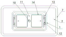
FIG. 2 is a schematic cross-sectional front view of a first connecting plate according to the present invention;
FIG. 3 is a schematic top view of a cross-sectional structure of the receiving slider according to the present invention;
FIG. 4 is a schematic top sectional view of the first adapter of the present invention;
FIG. 5 is a schematic side sectional view of the receiving plate according to the present invention;
FIG. 6 is an enlarged view of the structure at A in FIG. 1 according to the present invention.
In the figure: 1. a device housing; 2. a fixing plate; 3. a first connecting plate; 4. moving the slide block; 5. fixing the sleeve; 6. a damping spring; 7. a bearing plate; 8. a support base; 9. an electric motor; 10. rotating the screw; 11. placing the plate; 12. carrying the sliding block; 13. a second connecting plate; 14. a collection box; 15. a connecting hose; 16. a fixed tube; 17. a first adapter tube; 18. a second adapter tube; 19. a guide plate; 20. a sealing plate; 21. mounting a plate; 22. and (5) fastening the screw.
Detailed Description
The technical solutions in the embodiments of the present invention will be clearly and completely described below with reference to the drawings in the embodiments of the present invention, and it is obvious that the described embodiments are only a part of the embodiments of the present invention, and not all of the embodiments. All other embodiments, which can be derived by a person skilled in the art from the embodiments given herein without making any creative effort, shall fall within the protection scope of the present invention.
Referring to fig. 1-6, the present invention provides a technical solution: a sampling device for gold ore pulp is mainly used for extracting the gold ore pulp, and is convenient for detecting the content of each substance in the gold ore pulp;
the method comprises the following steps:
the device comprises a device shell 1, a fixed plate 2 is arranged outside the device shell, and a first connecting plate 3 is arranged at the lower end of the fixed plate 2;
the fixing sleeve 5 is attached to the first connecting plate 3, and a bearing plate 7 is arranged outside the fixing sleeve 5;
a supporting base 8 installed at the lower end of the bearing plate 7;
further comprising:
the movable sliding blocks 4 are symmetrically distributed about the center of the first connecting plate 3, and the movable sliding blocks 4 are in sliding connection with the fixed sleeve 5 through grooves formed in the fixed sleeve 5;
a damping spring 6 installed inside the fixing sleeve 5, and the damping spring 6 is installed at the lower end of the first connection plate 3;
the supporting base 8 is symmetrically distributed about the lower end of the bearing plate 7, and a base plate made of rubber is arranged at the lower end of the supporting base 8;
the motor 9 is placed at the upper end of the device shell 1, the output end of the motor 9 is connected with the rotating screw 10, and the rotating screw 10 and the device shell 1 form a rotating mechanism through a bearing arranged on the device shell 1;
the placing plate 11 is connected with the rotating screw 10 through a threaded hole formed in the upper end of the placing plate, and a threaded structure is arranged on the outer surface of the rotating screw 10;
in this example, two ends of the placing plate 11 are symmetrically provided with the receiving sliding blocks 12, the receiving sliding blocks 12 are arranged in a T shape, and the outer surfaces of the receiving sliding blocks 12 are smooth; the bearing slide block 12 is in sliding connection with the second connecting plate 13 through a groove formed in the second connecting plate 13, the second connecting plate 13 is installed on the inner surface of the device shell 1, and 2 second connecting plates 13 are arranged; 2 collecting boxes 14 are arranged at the upper end of the placing plate 11, a connecting hose 15 made of PVC is arranged at the upper end of each collecting box 14, a fixing pipe 16 is arranged at the upper end of each connecting hose 15, and the fixing pipe 16 is arranged on the device shell 1;
however, when the gold ore pulp needs to be sampled, the second connecting pipe 18 and the pulp temporary storage box are attached to each other, that is, the second connecting pipe 18 and the pulp in the temporary storage box are contacted with each other, then a valve arranged on the first connecting pipe 17 is opened, that is, the sample pulp is guided into the collecting box 14 through the second connecting pipe 18 and the first connecting pipe 17 for temporary storage, then the motor 9 starts to work, because the output end of the motor 9 is connected with the rotating screw 10, the rotating screw 10 starts to work, because the rotating screw 10 is connected with the placing plate 11 through a threaded hole formed in the placing plate 11, the placing plate 11 moves up and down under the action of the bearing slide block 12 along with the rotation of the rotating screw 10, and then the sample in the collecting box 14 can be taken out through the connecting hose 15 and the fixing pipe 16, so that the sample can be detected;
a first connecting pipe 17 is arranged at the lower end of the collecting box 14, the first connecting pipe 17 and a second connecting pipe 18 are attached to each other, and a guide plate 19 is arranged inside the first connecting pipe 17 and the second connecting pipe 18; a sealing plate 20 is arranged on the guide plate 19, an installation plate 21 is arranged on the guide plate 19 and the first connecting pipe 17, and a fastening screw 22 penetrates through the installation plate 21;
when the second connecting pipe 18 needs to be disassembled, the fastening screw 22 is rotated, the fastening screw 22 moves towards the direction far away from the mounting plate 21 until the fastening screw 22 and the nut are disassembled, then the fastening screw 22 can be taken down, then the second connecting pipe 18 is pulled, the second connecting pipe 18 starts to move towards the direction far away from the first connecting pipe 17 until the sealing plate 20 mounted on the guide plate 19 arranged inside the first connecting pipe 17 is not attached to the groove formed in the guide plate 19 arranged inside the second connecting pipe 18, at this time, the first connecting pipe 17 and the second connecting pipe 18 can be disassembled, so that the second connecting pipe 18 can be disassembled, and the device can be conveniently transported subsequently.
The working principle is as follows: when needs use this device, place this device in the assigned position, then make motor 9 begin work, motor 9 just drives and rotates screw rod 10 and rotate, just make this moment and place board 11 and reciprocate under the effect of accepting slider 12, the realization is taken a sample to the ore pulp of co-altitude not, the ore pulp after the sample just gets into in collecting box 14, later can realize taking out the sample after mixing in collecting box 14 through coupling hose 15 and fixed pipe 16, the realization detects the sample, and set up to detachable construction between first takeover 17 and the second takeover 18, thereby be convenient for dismantle second takeover 18, along with second takeover 18 is dismantled, be convenient for transport this takeover device, this is exactly this a sampling device's for gold mine ore pulp theory of operation.
Although embodiments of the present invention have been shown and described, it will be appreciated by those skilled in the art that changes, modifications, substitutions and alterations can be made in these embodiments without departing from the principles and spirit of the utility model, the scope of which is defined in the appended claims and their equivalents.
Claims (6)
1. A sampling device for gold ore pulp is mainly used for extracting the gold ore pulp, and is convenient for detecting the content of each substance in the gold ore pulp;
the method comprises the following steps:
the device comprises a device shell, a first connecting plate and a second connecting plate, wherein a fixing plate is arranged outside the device shell, and the lower end of the fixing plate is provided with the first connecting plate;
the fixing sleeve is mutually attached to the first connecting plate, and a bearing plate is arranged outside the fixing sleeve;
the supporting base is arranged at the lower end of the bearing plate;
it is characterized by also comprising:
the movable sliding blocks are symmetrically distributed about the center of the first connecting plate and are in sliding connection with the fixed sleeve through grooves formed in the fixed sleeve;
the damping spring is installed inside the fixing sleeve and is installed at the lower end of the first connecting plate;
the supporting base is symmetrically distributed about the lower end of the bearing plate, and a base plate made of rubber is mounted at the lower end of the supporting base;
the motor is placed at the upper end of the device shell, the output end of the motor is connected with the rotating screw rod, and the rotating screw rod and the device shell form a rotating mechanism through a bearing arranged on the device shell;
the placing plate is connected with the rotating screw through a threaded hole formed in the upper end of the placing plate, and a threaded structure is arranged on the outer surface of the rotating screw.
2. A sampling device for gold ore pulp according to claim 1 wherein: the placing plate is characterized in that two ends of the placing plate are symmetrically provided with bearing sliding blocks, the bearing sliding blocks are arranged to be T-shaped, and the outer surfaces of the bearing sliding blocks are smooth.
3. A sampling device for gold ore pulp according to claim 2 wherein: the bearing slide block and the second connecting plate form sliding connection through a groove formed in the second connecting plate, the second connecting plate is installed on the inner surface of the device shell, and the number of the second connecting plates is 2.
4. A sampling device for gold ore pulp according to claim 1 wherein: place the board upper end and install 2 collecting boxes, just the coupling hose of PVC material is installed to the collecting box upper end, and the coupling hose upper end is installed fixed pipe, simultaneously fixed pipe is installed on the device shell.
5. A sampling device for gold ore pulp according to claim 4 wherein: the collecting box is characterized in that a first connecting pipe is installed at the lower end of the collecting box, the first connecting pipe and a second connecting pipe are attached to each other, and a guide plate is installed inside the first connecting pipe and the second connecting pipe.
6. A sampling device for gold ore pulp according to claim 5 wherein: the guide plate is provided with a sealing plate, the guide plate and the first connecting pipe are provided with a mounting plate, and a fastening screw penetrates through the mounting plate.
Priority Applications (1)
| Application Number | Priority Date | Filing Date | Title |
|---|---|---|---|
| CN202121936325.2U CN215931341U (en) | 2021-08-18 | 2021-08-18 | Sampling device for gold ore pulp |
Applications Claiming Priority (1)
| Application Number | Priority Date | Filing Date | Title |
|---|---|---|---|
| CN202121936325.2U CN215931341U (en) | 2021-08-18 | 2021-08-18 | Sampling device for gold ore pulp |
Publications (1)
| Publication Number | Publication Date |
|---|---|
| CN215931341U true CN215931341U (en) | 2022-03-01 |
Family
ID=80423289
Family Applications (1)
| Application Number | Title | Priority Date | Filing Date |
|---|---|---|---|
| CN202121936325.2U Active CN215931341U (en) | 2021-08-18 | 2021-08-18 | Sampling device for gold ore pulp |
Country Status (1)
| Country | Link |
|---|---|
| CN (1) | CN215931341U (en) |
-
2021
- 2021-08-18 CN CN202121936325.2U patent/CN215931341U/en active Active
Similar Documents
| Publication | Publication Date | Title |
|---|---|---|
| CN215931341U (en) | Sampling device for gold ore pulp | |
| CN221325988U (en) | Portable water sample collection equipment | |
| CN221764962U (en) | Sampling device and water quality detection equipment | |
| CN116123387B (en) | Pipeline collection robot and collection method | |
| CN117451426A (en) | River channel water level water resource evaluation and detection integrated treatment system | |
| CN216899677U (en) | Sampling and cutting device for building detection | |
| CN116165358A (en) | Water quality testing platform for river channel diversified ecological system | |
| CN215833055U (en) | Powder sampling device in concrete production | |
| CN115586038A (en) | Water treatment facilities with water source sampling function | |
| CN212432686U (en) | Chemical industry safety ring protects gaseous sampling device | |
| CN221350732U (en) | Sewage sampling device for laboratory | |
| CN214584134U (en) | Food detection sampling device | |
| CN114236076A (en) | Movable water pollution monitoring device | |
| CN209148331U (en) | A soil nematode community sample collection device | |
| CN220357056U (en) | Sewage detection device for informatization construction | |
| CN220380818U (en) | Water pollution sampling device | |
| CN112881634A (en) | Intelligent detection instrument with intercepting blowdown structure for pipe installation | |
| CN220812179U (en) | Sludge low-temperature drying box | |
| CN220018978U (en) | Self-positioning electric control soil sampler for large-scale consolidation apparatus | |
| CN222299248U (en) | Sewage detection device for chemical drainage pipeline | |
| CN221523510U (en) | Soil sampling device with complete sampling | |
| CN211527882U (en) | Agricultural technology promotes and uses soil sampling device | |
| CN221325992U (en) | Building material sampling device is built in room | |
| CN219475051U (en) | Building material sampling device | |
| CN219104387U (en) | Soil collecting device is surveyed to soil |
Legal Events
| Date | Code | Title | Description |
|---|---|---|---|
| GR01 | Patent grant | ||
| GR01 | Patent grant |