SUMMERY OF THE UTILITY MODEL
The application provides an ink horn of printer, this ink horn can reduce to the gas filled number of times in the deformation air cavity, reduces the cracked risk of deformation membrane, makes the ink horn normally supply ink to the printer.
The embodiment of the application provides an ink horn of printer, the ink horn includes: the ink storage box comprises a box body and a control device, wherein the box body is provided with an ink storage cavity for storing ink, and an ink supply port communicated with the ink storage cavity; deforming the film; the ink storage cavity is internally provided with a deformation air cavity communicated with a printer pump, the deformation film forms at least two mutually-spaced side walls of the deformation air cavity, and the deformation film can deform and is used for driving ink in the ink storage cavity to be discharged from the ink supply port.
In one possible design, the deformation membrane includes at least a first deformation membrane and a second deformation membrane which are separately arranged, and the first deformation membrane and the second deformation membrane form two opposite side walls of the deformation air cavity.
In one possible design, the first deformable membrane and the second deformable membrane are mounted to the box body, and the first deformable membrane, the second deformable membrane and the box body enclose the deformable air chamber. In one possible design, the cartridge body has a deformation ink chamber, and the deformation ink chamber and the deformation air chamber are separated by the first deformation film; an elastic piece is arranged on one side, away from the second deformation membrane, of the first deformation membrane, and the elastic piece is located in the deformation ink cavity; the ink storage cavity is communicated with the deformation ink cavity through a communication port.
In one possible design, the amount of deformability of the first deformable membrane is greater than the amount of deformability of the second deformable membrane.
In one possible design, the box body is also provided with an inflation inlet communicated with the deformation air cavity; the pump of the printer can inflate the deformable air cavity through the inflation port.
In one possible design, the box body is further provided with an air inlet communicated with the ink storage cavity, and a control valve is arranged between the air inlet and the ink supply port; in the process of inflating the deformation air cavity, the control valve is in a closed state; when the deformed air chamber stops being inflated, the control valve is in an open state, so that the ink storage cavity is communicated with the outside through the air inlet.
In one possible design, the control valve includes a valve body, the box body has a gas passage and an installation space, and the gas passage communicates the gas inlet and the installation space; the valve body is positioned in the mounting space and can move in the mounting space to block or open the gas channel.
In one possible design, the valve body is of a spherical structure.
In one possible design, the control valve further includes an air outlet that is higher than the ink supply port, or the air outlet is offset from the ink supply port.
In this application, the box body of ink horn is including holding ink chamber, and the ink storage is in holding ink chamber. When the printer needs the ink box to provide ink, the deformation air cavity in the ink storage cavity expands and deforms, the volume of the deformation air cavity is increased, the pressure in the ink storage cavity is increased, positive pressure is formed, and the ink in the ink storage cavity is pushed to flow out from the ink supply port so as to provide ink for the printer. In this ink supply process, because the deformation air cavity has two lateral walls at least and is formed by the deformation membrane, consequently, can be to two at least orientation inflation deformation after the deformation air cavity is aerifyd to can increase the ink volume that extrudes when the deformation air cavity expands at every turn, when guaranteeing that the ink horn provides sufficient ink for the printer, can reduce the deformation air cavity and aerify the number of times of deformation, thereby reduce the deformation membrane because of aerifing the too much cracked risk of inflation number of times, improve the life of deformation membrane.
Meanwhile, the deformed air cavity has smaller volume before expansion, occupies smaller volume of the ink storage cavity and does not influence the ink storage amount of the ink box.
It is to be understood that both the foregoing general description and the following detailed description are exemplary and explanatory only and are not restrictive of the application.
Detailed Description
For better understanding of the technical solutions of the present application, the following detailed descriptions of the embodiments of the present application are provided with reference to the accompanying drawings.
It should be understood that the embodiments described are only a few embodiments of the present application, and not all embodiments. All other embodiments, which can be derived by a person skilled in the art from the embodiments given herein without making any creative effort, shall fall within the protection scope of the present application.
The terminology used in the embodiments of the present application is for the purpose of describing particular embodiments only and is not intended to be limiting of the application. As used in the examples of this application and the appended claims, the singular forms "a", "an", and "the" are intended to include the plural forms as well, unless the context clearly indicates otherwise.
It should be understood that the term "and/or" as used herein is merely one type of association that describes an associated object, meaning that three relationships may exist, e.g., a and/or B may mean: a exists alone, A and B exist simultaneously, and B exists alone. In addition, the character "/" herein generally indicates that the former and latter related objects are in an "or" relationship.
It should be noted that the terms "upper", "lower", "left", "right", and the like used in the embodiments of the present application are described in terms of the angles shown in the drawings, and should not be construed as limiting the embodiments of the present application. In addition, in this context, it will also be understood that when an element is referred to as being "on" or "under" another element, it can be directly on "or" under "the other element or be indirectly on" or "under" the other element via an intermediate element.
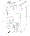
The embodiment of the application provides an ink box of a printer, which is used for providing ink for the printer. As shown in fig. 1 to 4, the ink cartridge includes a cartridge body 1 and a deformable film, the cartridge body 1 has an ink storage chamber 11 for storing ink, and the cartridge body 1 is further provided with an ink supply port 111 communicating with the ink storage chamber 11. Wherein, the ink storage cavity 11 has a deformation air cavity 2 therein, and the deformation film forms at least two mutually spaced side walls of the deformation air cavity 2, and the deformation film can be deformed for driving the ink in the ink storage cavity 11 to be discharged from the ink supply port 111.
In the present embodiment, the cartridge body 1 has an inner cavity, which is an ink storage chamber 11, and ink is stored in the ink storage chamber 11. When the printer needs the ink box to provide ink, the deformation air cavity 2 in the ink storage cavity 11 expands and deforms, the volume of the deformation air cavity 2 is increased, the pressure in the ink storage cavity 11 is increased, positive pressure is formed, and the ink in the ink storage cavity 11 is pushed to flow out from the ink supply port 111 to provide ink for the printer. In this ink supply process, because the deformation air cavity 2 has two mutual spaced lateral walls at least and is formed by the deformation membrane, consequently, can be to two at least orientation inflation deformation after the deformation air cavity 2 aerifys to can increase the ink volume that extrudes when the deformation air cavity 2 expands at every turn, when guaranteeing that the ink horn provides sufficient ink for the printer, can reduce the number of times that the deformation air cavity 2 aerifys the deformation, thereby reduce the deformation membrane because of aerifing the too much cracked risk of inflation number of times, improve the life of deformation membrane.
Meanwhile, the volume of the deformation air cavity 2 before expansion is small, the volume occupied by the ink storage cavity 11 is small, and the ink storage capacity of the ink box is not influenced.
In a specific embodiment, as shown in fig. 4 and 5, the deformable film includes at least a first deformable film 21 and a second deformable film 22 which are separately disposed, and the first deformable film 21 and the second deformable film 22 form two opposite side walls of the deformable air chamber 2.
In the present embodiment, when the first deformable film 21 and the second deformable film 22 form the opposite side walls of the deformable air chamber 2 so that the deformable air chamber 2 is deformed by expansion, the deformation directions of the first deformable film 21 and the second deformable film 22 are opposite, so that the discharge of ink from the ink supply port 111 is further promoted by the first deformable film 21 and the second deformable film 22 applying pressing forces in opposite directions to the ink in the ink reservoir 11. Meanwhile, when the first deformable film 21 and the second deformable film 22 are separately arranged, the two films can be conveniently and independently mounted, and the materials and the shapes of the first deformable film 21 and the second deformable film 22 can be conveniently and reasonably selected according to needs, so that the deformation of the two films can be changed according to needs.
The first deformable film 21 and the second deformable film 22 provided separately may be deformable films of the same material or different materials, as long as they are elastically deformable.
Further, as shown in fig. 4, the side of the first deformable film 21 away from the second deformable film 22 is provided with an elastic member 18.
In this embodiment, when the printer needs the ink cartridge to provide ink, the deformable air chamber 2 is inflated to deform the first deformable membrane 21 and the second deformable membrane 22 in the direction away from each other under the action of pressure, so as to squeeze the ink in the ink storage chamber 111 to supply ink to the printer from the ink supply port 111, and the elastic member 18 can be squeezed to make the elastic member 18 in a compressed state in the process of deformation of the first deformable membrane 21; when the printer is in the condition that the ink box does not need to provide ink such as printing state or standby, the deformation air cavity 2 no longer expands, and the effect that first deformation membrane 21 extrudes elastic component 18 disappears, and under the resilience effect, elastic component 18 resumes original shape, and under the resilience effect of elastic component 18, can push back original position with first deformation membrane 21, and the storage ink chamber 11 internal pressure reduces, and the malleation state disappears, no longer drives the ink and flows out from supplying ink mouth 111. In addition, when the deformation air chamber 2 expands due to a large change in the temperature of the use environment of the ink cartridge, the elastic member 18 pushes the first deformation film 21 back to the pre-expansion state, so that the pressure in the ink storage chamber 11 decreases and the ink is no longer driven to flow out from the ink supply port 111.
Therefore, in the present embodiment, by providing the elastic member 18, the first deformation film 21 can be driven to return to the initial position, so that ink supply from the ink cartridge is quickly stopped, and ink leakage from the ink supply port 111 is prevented.
The elastic member 18 may be a spring or other object capable of elastically deforming. The side of the elastic element 18 far away from the first deformation film 21 is fixedly connected with the box body 1, so that the elastic element 18 can not move along with the change of the position and the direction of the ink box.
In addition, the elastic member 18 may be a conical spring, one end of the conical spring with a large cross section is fixedly connected to the case 1, so that the connection reliability between the elastic member 18 and the case 1 is improved, and the other end of the conical spring with a small cross section is in contact with the first deformation film 21, so that the stress of the elastic member 18 on the first deformation film 21 is increased. When the spring is pressed by the first deformation film 21, the small ring part close to the first deformation film 21 can be retracted into the large ring part far away from the first deformation film 21, when the ink in the ink box is less, the amount of the ink which can not be discharged around the spring is reduced, and the ink box can provide more ink for the printer under the condition of not increasing the volume of the box body 1.
In another specific embodiment, the deformable amount of the first deformation film 21 is larger than the deformable amount of the second deformation film 22. The material with the larger elastic coefficient is selected as the first deformation film 21, the material with the elastic coefficient smaller than that of the first deformation film 21 is selected as the second deformation film 22, and the deformation amount of the first deformation film 21 is larger than that of the second deformation film 22 when the deformation air cavity 2 expands.
Specifically, when the printer needs the ink box to provide ink, the deformation air cavity 2 expands, and the first deformation film 21 extrudes the elastic element 18 to deform; after the ink cartridge provides sufficient ink for the printer, the deformation air cavity 2 needs to return to the state before expansion, at this moment, the second deformation membrane 22 restores the initial state under the resilience effect of self, the first deformation membrane 21 restores the initial state under the resilience effect of self resilience and elastic member 18, therefore, the restoring force that the second deformation membrane 22 received is greater than the restoring force that the first deformation membrane 21 received, the deformation air cavity 2 restores the in-process of initial state, the deflection of the first deformation membrane 21 is greater than the deflection of the second deformation membrane 22. In this embodiment, by setting the deformable amount of the first deformable film 21 to be larger than the deformable amount of the second deformable film 22, it is possible to reduce the risk that the first deformable film 21 is damaged by its own resilient force and the resilient force of the elastic member 18 while quickly restoring the first deformable film 21 to the initial state.
Further, as shown in fig. 4, the first deformable film 21 and the second deformable film 22 are attached to the case body 1, and the first deformable film 21, the second deformable film 22, and the case body 1 enclose the deformable air chamber 2.
In the present embodiment, the first deformable film 21, the second deformable film 22, and the side walls of the mounting portion 12 of the cartridge body 1 between the deformable films together enclose the deformable air chamber 2. On one hand, the position of the deformed air cavity 2 is determined, and the position of the deformed air cavity 2 in the ink storage cavity 11 cannot change along with the movement of the ink box, so that the ink box is stable; on the other hand, when the deformation air chamber 2 expands, the length of the side wall of the mounting part 12 between the deformation films is small and does not deform, so that the deformation amount of the first deformation film 21 and the second deformation film 22 is larger, the driving effect on ink is stronger, and the elastic action of the elastic element 18 makes the deformation air chamber 2 recover the state before expansion faster.
The mounting portion 12 is located in the ink storage chamber 11 and is formed by the internal structure of the case 1. The first deformable film 21 and the second deformable film 22 may be attached to the attachment portion 12 by pressure welding, adhesion, or the like.
Further, as shown in fig. 3 and 4, the cartridge body 1 has a deformed ink chamber 19, and the elastic member 18 is located in the deformed ink chamber 19; the ink storage chamber 11 and the deformed ink chamber 19 are communicated through a communication port 17.
Specifically, the first deformation film 21 and the mounting portion 12 enclose a deformation ink chamber 19, the deformation ink chamber 19 can be filled with ink and the elastic member 18, the first deformation film 21 pushes the elastic member 18 to deform and simultaneously pushes the ink in the deformation ink chamber 19 to flow into the ink storage chamber 11 through the communication port 17, the ink in the ink storage chamber 11 flows out from the ink supply port 111 to provide ink for printing, and the sectional area of the communication port 17 is small, so that the flow rate of the ink entering the ink storage chamber 11 from the deformation ink chamber 19 can be increased, and the ink is further promoted to be discharged from the ink supply port 111.
In this embodiment, as shown in fig. 1 and 4, the box body 1 is further provided with an inflation inlet 14 communicated with the deformation air cavity 2; the pump of the printer can inflate the deformable air cavity 2 through the inflation inlet 14, the air in the deformable air cavity 2 is increased, the air pressure is increased, and the deformable air cavity expands outwards, so that the ink in the ink storage cavity 11 is driven to be discharged from the ink supply port 111 to supply ink for the printer. After the ink horn provides sufficient ink for the printer, the state before the inflation need be got back to deformation air cavity 2, no longer aerifys to deformation air cavity 2, and deformation air cavity 2 is pushed back original state under the resilience force of first deformation membrane 21 and the resilience force effect of elastic component 18, and at this moment, the gas passes through inflation inlet 14 and discharges in the deformation air cavity 2, prevents that deformation air cavity 2 that the too big result in of air pressure in the deformation air cavity 2 can't reply original state.
The diameter of the inflation inlet 14 can be selected as required, so as to increase the rate of inflating the deformation air cavity 2 and further improve the efficiency of the ink supply process of the ink box.
Further, as shown in fig. 7 to 10, the box body 1 is further provided with an air inlet 13 communicated with the ink storage chamber 11, and a control valve 16 is arranged between the air inlet 13 and the ink supply port 111; in the process of inflating the deformable air cavity 2, the control valve 16 is in a closed state, when the inflation of the deformable air cavity 2 is stopped, the control valve 16 is in an open state, when the control valve 16 is opened, the ink storage cavity 11 can be communicated with the outside through the air inlet 13, and when the control valve 16 is closed, the ink storage cavity 11 is disconnected from the outside.
In this embodiment, when the print head of the printer lacks ink, the deformable air chamber 2 is inflated through the inflation port 14, so that the deformable air chamber 2 expands under the pressure of the air, so as to form positive pressure in the ink storage chamber 11, thereby pushing the ink in the ink storage chamber 11 to be discharged through the ink supply port 111, supplying ink to the printer, and starting printing by the printer, and in this process, the control valve 16 is closed, so as to prevent the ink in the ink storage chamber 11 from leaking from the control valve 16. When the printer is in a normal printing state, the deformed air chamber 2 is stopped from being inflated, so that the deformed air chamber 2 returns to an original state, the pressure in the ink storage chamber 11 is reduced to form negative pressure, the control valve 16 is opened under the action of the negative pressure, the ink storage chamber 11 is communicated with the outside through the air inlet 13, the pressure difference between the ink storage chamber 11 and the outside is balanced, ink in the ink storage chamber 11 can be smoothly discharged from the ink supply port 111, and continuous ink supply of the ink box to the printer is realized. Therefore, in this embodiment, by providing the control valve 16, not only can continuous ink supply from the ink cartridge to the printer be achieved, but also ink leakage from the ink cartridge can be prevented.
Specifically, as shown in fig. 3 to 10, the control valve 16 includes a valve body 162, the box body 1 has a gas passage and an installation space 161, and the gas passage communicates the gas inlet 13 and the installation space 161; the valve body 162 is located in the installation space 161 and can move in the installation space 161 to close or open the gas passage.
In this embodiment, the valve body 162 of the control valve 16 can move along the mounting space 161 under the pressure in the ink storage chamber 11, so as to block or open the gas passage to block or communicate the outside with the ink storage chamber 11, and the valve body 162 can roll in the mounting space 161, thereby reducing the resistance. When the deformation air chamber 2 expands to form positive pressure in the ink storage chamber 11, as shown in fig. 7 and 8, the valve body 162 blocks the air passage under the action of the positive pressure; when the deformed air chamber 2 returns to the original state so that negative pressure is formed in the ink reservoir 11, as shown in fig. 9 and 10, the valve body 162 opens the gas passage by the negative pressure, so that the gas in the ink reservoir 11 can flow to the outside in the direction indicated by the arrow in fig. 10.
More specifically, the internal structure of the cartridge 1 forms a mounting space 161 and a gas passage composed of three parts communicating with each other, i.e., a first gas passage 3 (FIG. 3), a second gas passage 4 (FIG. 6), and a third gas passage 5 (FIGS. 7 to 10). Wherein the first gas channel 3 is directly communicated with the gas inlet 13, the control valve 16 is arranged on the third gas channel 5, and the second gas channel 4 is communicated with the first gas channel 3 and the third gas channel 5, thereby communicating the ink storage cavity 11 and the outside through the first gas channel 3, the second gas channel 4 and the third gas channel 5.
Meanwhile, as shown in fig. 8 and 10, one end of the control valve 16 away from the third gas passage 5 may be provided with a first filter 163, and as shown in fig. 6, a second filter 41 is provided where the first gas passage 3 and the second gas passage 4 communicate with each other. In the process that the air enters the ink storage cavity 11 from the air inlet 13, impurities in the air can be filtered out by the two layers of filter screens, and the quality of the ink in the ink storage cavity 11 is guaranteed.
In this embodiment, the gas channel may be a labyrinth-type channel. The air passage is arranged in a labyrinth type, so that the length of the air passage can be increased without increasing the weight of the ink box. The longer the length of the gas passage, the slower and gentler the gas speed entering the ink storage cavity 11 from the gas passage, the fluctuation of the ink in the ink storage cavity 11 can not be excited, thereby preventing the ink in the ink storage cavity 11 from generating bubbles to influence the quality of the ink when the ink is supplied by the ink box.
Meanwhile, as shown in fig. 2, a first sealing film 6 is arranged between the first gas channel 3 and the ink storage cavity 11, and the first sealing film 6 separates the gas in the first gas channel 3 from the ink in the ink storage cavity 11; a second sealing film 7 is arranged between the second air channel 4 and the outside, the second sealing film 7 separates the air in the second air channel 4 from the outside, and the air inlet 13 and the air outlet 112 at the whole air channel are good in external sealing performance.
In one particular embodiment, the valve body 162 is a ball structure. When the valve body 162 has a spherical structure, friction during movement in the control valve 16 is small, and the control valve has high sensitivity.
Meanwhile, the valve body 162 may be designed in other shapes to block or open the gas passage.
Further, as shown in fig. 9 and 10, the control valve 16 further includes an air outlet 112, and the air outlet 112 is higher than the ink supply port 111, or the air outlet 112 is offset from the ink supply port 111.
In this embodiment, when the control valve 16 is opened, as shown in fig. 9 and 10, the air enters the ink storage chamber 11 through the air inlet 13, the air passage, the control valve 16 and the air outlet 112, and when the air outlet 112 is higher than the ink supply port 111, the air directly flows in from above the ink supply port 111, so as to prevent the ink entering the print head through the ink supply port 111 from generating bubbles; when the air outlet 112 is staggered with the ink supply port 111, the air can be prevented from directly mixing with the ink when entering from the air outlet 112 and then being discharged from the ink supply port 111, so that the ink entering the printing head through the ink supply port 111 is prevented from generating bubbles, and the printing quality is improved.
Wherein, the air outlet 112 and the ink supply port 111 may be constituted by the third sealing film 8 fixed in the ink storage chamber 11 and the inner structure of the cartridge body 1.
An embodiment of the present application further provides a printer, including: a print head; an ink cartridge according to any one of the above embodiments; wherein the ink supply port 111 communicates with the print head. The ink box body 1 is provided with an ink outlet 15, the ink outlet 15 is communicated with the ink supply port 111, and when the printer works, ink can enter the printing head through the ink supply port 111 and the ink outlet 15 in sequence to provide ink for printing. Since the ink box has the technical effects, the printer comprising the ink box also has corresponding technical effects, and the details are not repeated herein.
Specifically, the printer further includes a detection portion for detecting the amount of ink of the print head, and a control portion for inflating the deformation air chamber 2 when the detection portion detects that the amount of ink is insufficient, and for controlling the deformation air chamber 2 to stop inflating when the detection portion detects that the amount of ink is sufficient.
In this embodiment, after the ink cartridge is installed in the printer or when the ink in the print head is insufficient, the control unit controls the gas to inflate the deformable air cavity 2 through the inflation inlet 14 under the control of the detection result of the detection unit, so that the deformable air cavity 2 expands, a positive pressure is formed in the ink storage cavity 11, and the positive pressure drives the ink in the ink storage cavity 11 to flow to the print head through the ink supply port 111 and the ink outlet port 15; when the printer works normally, after the detection part in the printing head detects that the ink is enough, the controller controls the deformed air chamber 2 not to be inflated any more, the first deformation film 21 of the deformed air chamber 2 is pushed back to the position before expansion under the action of the elastic part 18, negative pressure is formed in the ink storage chamber 11, and under the action of the negative pressure, the ink does not flow to the printing head through the ink supply port 111 and the ink outlet port 15 any more, so that the ink box of the printer cannot leak the ink under the normal printing state. Therefore, by providing the detection portion and the control portion, it is possible to automatically control whether to inflate the inside of the deformed air chamber 2 according to the operating state of the printer, thereby preventing ink leakage while supplying ink to the inside of the print head through the ink cartridge.
The above description is only a preferred embodiment of the present application and is not intended to limit the present application, and various modifications and changes may be made by those skilled in the art. Any modification, equivalent replacement, improvement and the like made within the spirit and principle of the present application shall be included in the protection scope of the present application.