CN214409261U - Current measurement calibration system - Google Patents
Current measurement calibration system Download PDFInfo
- Publication number
- CN214409261U CN214409261U CN202023071951.8U CN202023071951U CN214409261U CN 214409261 U CN214409261 U CN 214409261U CN 202023071951 U CN202023071951 U CN 202023071951U CN 214409261 U CN214409261 U CN 214409261U
- Authority
- CN
- China
- Prior art keywords
- load
- current
- calibration
- module
- logic control
- Prior art date
- Legal status (The legal status is an assumption and is not a legal conclusion. Google has not performed a legal analysis and makes no representation as to the accuracy of the status listed.)
- Withdrawn - After Issue
Links
- 238000005259 measurement Methods 0.000 title claims abstract description 53
- 238000004891 communication Methods 0.000 claims abstract description 4
- 239000011159 matrix material Substances 0.000 claims description 24
- 238000004164 analytical calibration Methods 0.000 claims description 7
- 238000004364 calculation method Methods 0.000 claims description 4
- 229910044991 metal oxide Inorganic materials 0.000 claims description 3
- 150000004706 metal oxides Chemical class 0.000 claims description 3
- 239000004065 semiconductor Substances 0.000 claims description 3
- 238000012360 testing method Methods 0.000 abstract description 8
- 230000006870 function Effects 0.000 abstract description 5
- 238000010586 diagram Methods 0.000 description 8
- 238000000034 method Methods 0.000 description 5
- 230000010354 integration Effects 0.000 description 3
- 238000013075 data extraction Methods 0.000 description 1
- 238000013500 data storage Methods 0.000 description 1
- 238000001514 detection method Methods 0.000 description 1
- 238000011161 development Methods 0.000 description 1
- 230000018109 developmental process Effects 0.000 description 1
- 230000000694 effects Effects 0.000 description 1
- 238000005516 engineering process Methods 0.000 description 1
- 230000011218 segmentation Effects 0.000 description 1
- 238000001228 spectrum Methods 0.000 description 1
Images


Landscapes
- Measurement Of Current Or Voltage (AREA)
Abstract
The utility model provides a low-cost, small, high accuracy, easily integrated and have calibration function's current measurement calibration system. The utility model discloses the system includes logic control unit (1), current measurement unit (2), memory cell (3) and host computer (4), logic control unit respectively with current measurement unit, memory cell and host computer communication connection. The utility model discloses can be applied to the test field.
Description
Technical Field
The utility model relates to an electronic product detection area especially relates to a current measurement calibration system.
Background
For electronic products, current is a necessary index for measuring the functions and performance of the products. All electronic products require current measurement before leaving the factory to ensure product quality. With the improvement of functions and performances of electronic products, technical requirements such as low power consumption, low current, rapid charging, high current and the like tend to be common. In order to accurately judge whether the product works normally, the current measurement result is required to be very accurate. The conventional solution mainly uses standard instruments such as Keysight 34465A, Keysight 34470A to measure the current, and the whole structure is shown in FIG. 1. However, standard measurement instruments are expensive and are not suitable for use in testing/measuring of bulk products; and the current measurement requirements of electronic products under the new trend are flexible and changeable, and the standard measurement instrument is difficult to meet the consumer electronics test industry under the new trend. With the development of technology, analog and digital circuits are increasingly used in the test equipment industry to implement current measurement functions, rather than standard instruments. However, when current measurement is performed using analog and digital circuits, the current measurement system needs to be calibrated to ensure measurement accuracy. The conventional calibration method is to calibrate the current using a standard current source, and the system architecture is shown in fig. 2. However, the existing standard current source is large in volume, difficult to integrate, and expensive, and is not suitable for the consumer electronics product testing industry under new trend, which increases the measurement cost of the electronic product.
SUMMERY OF THE UTILITY MODEL
The utility model aims to solve the technical problem that overcome prior art not enough, provide a low cost, small, high accuracy, easily integrated and have the current measurement calibration system of calibration function.
The technical scheme that current calibration system adopted is: the device comprises a logic control unit, a current measuring unit, a storage unit and an upper computer, wherein the logic control unit is respectively in communication connection with the current measuring unit, the storage unit and the upper computer,
the logic control unit is used for receiving an instruction signal from the upper computer, collecting a signal of the current measuring unit, sending a control signal to the current measuring unit and storing a calibration coefficient into the storage unit;
the current measuring unit is used for connecting a product to be measured, supplying power to the product to be measured, receiving signals sent by the logic control unit and the upper computer and sending signals to the logic control unit and the upper computer;
the storage unit is used for storing the calibration parameters sent by the logic control unit;
the upper computer is used for sending instruction signals to the logic control unit, receiving signals uploaded by the logic control unit, calculating a calibration coefficient of the system, and sending the calibration coefficient to the storage unit for storage;
the current measuring unit comprises a power supply module, a power supply matrix, a universal calibration board, an instrument interface and a load module, the power supply module supplies power to a product to be measured, the load module, the universal calibration board and the instrument interface through the power supply matrix, a DAC module of the logic control unit generates a plurality of analog voltages to drive the load module, the load module generates a constant current load, the upper computer reads current values through the current measuring unit and a standard instrument connected to the universal calibration board and the instrument interface respectively, obtains two groups of current values through calculation to obtain calibration coefficients, writes the obtained calibration coefficients into the storage unit, and then selects the power supply path and the load path to carry out current calibration of the current measuring unit by using the calibration coefficients.
The power supply module provides a VBUS power supply and a VBATT power supply, current sensors are arranged on the paths of the two power supplies, the current sensors convert current on the power supply path into voltage, the voltage is measured through an ADC module connected with the current sensors, and the ADC module is connected with the logic control unit through an SPI bus and outputs a current measurement result of the power supply.
The power supply matrix is composed of a relay, and the power supply matrix switches whether a power supply loop of the VBUS power supply and the VBATT power supply is connected to the universal calibration board and an instrument interface.
The universal calibration board and the instrument interface comprise an MOS (metal oxide semiconductor) tube switching path and an instrument calibration interface, the MOS tube switching path comprises a plurality of channels, and the instrument calibration interface is connected with a current calibration standard instrument when the power module and the load module are subjected to current calibration.
The load module comprises a plurality of load channels, a channel switch and a following amplifier, wherein each load channel comprises a channel DAC module, a voltage amplifier and a constant current load which are sequentially connected, the channel DAC module is used for setting the load current, the constant current load is used for simulating and generating the constant current load, and the channel switch is used for switching the load channels.
The load module is further connected with a load switching matrix, the other side of the load switching matrix is connected with a product to be tested, and the load switching matrix is used for switching different load channels to be connected with the product to be tested.
The utility model has the advantages that: the utility model discloses in, power module pass through the power supply matrix to the product that awaits measuring, load module with general calibration board and instrument interface power supply general calibration board and instrument interface connect the standard instrument, logic control unit's DAC module produces a plurality of analog voltage and drives the load module, the load module produces the constant current load, the host computer respectively through current measurement unit, be connected to the standard instrument on general calibration board and the instrument interface reads the current value, the host computer obtains two sets of current values, through calculating, obtains the calibration coefficient, the host computer writes in the calibration coefficient who obtains storage element, then utilize the calibration coefficient respectively to carry out the current calibration to current measurement unit's power supply path and load path; it can be seen that, the utility model discloses a current measurement, calibration scope are wide: it can measure 10 mA-5A current; the measurement accuracy is high: the 32bit ADC is adopted, and the precision can reach +/-1 thousandth +/-2 mA; a universal calibration board and an instrument interface are adopted, so that the integration level is high, and the system is flexible and expandable; in addition, the utility model has low system cost, and can calibrate a plurality of parameters at one time, such as VBUS current, E _ Load setting voltage and I _ Load current; the utility model realizes high precision measurement and calibration of current, and the system is simple to build; the data storage and extraction are convenient, and the problems of high current measurement cost, difficult integration and the like are solved, so that the method can be applied to electronic test/measurement equipment.
Drawings
FIG. 1 is a simplified prior art architecture diagram for current sensing using standard instrumentation;
FIG. 2 is a simplified prior art architecture diagram for current sensing using analog and digital circuitry;
FIG. 3 is a block diagram of the simple system structure of the present invention;
FIG. 4 is a block diagram showing a simple structure of the current measuring unit;
FIG. 5 is a block diagram of a simplified configuration of the power module;
FIG. 6 is a block diagram of a simplified structure of the power supply matrix;
FIG. 7 is a simplified block diagram of the universal calibration board and instrument interface;
fig. 8 is a block diagram showing a simple structure of the load module.
Detailed Description
The utility model discloses as follows specifically.
As shown in fig. 3 to 8, the current measurement calibration system of the present invention includes a logic control unit 1, a current measurement unit 2, a storage unit 3 and an upper computer 4, wherein the logic control unit 1 is respectively in communication connection with the current measurement unit 2, the storage unit 3 and the upper computer 4, and the logic control unit 1 is configured to receive an instruction signal from the upper computer 4, collect a signal of the current measurement unit 2, send a control signal to the current measurement unit 2, and store a calibration coefficient in the storage unit 3; the current measuring unit 2 is used for connecting a product to be measured, supplying power to the product to be measured, receiving signals sent by the logic control unit 1 and the upper computer 4, and sending signals to the logic control unit 1 and the upper computer 4; the storage unit 3 is configured to store the calibration parameters sent by the logic control unit 1; the upper computer 4 is used for sending instruction signals to the logic control unit 1, receiving signals uploaded by the logic control unit 1, calculating calibration coefficients of a system and sending the calibration coefficients to the logic control unit 1The storage unit 3 stores; the current measuring unit 2 comprises a power module 21, a power supply matrix 22, a universal calibration board and instrument interface 23 and a load module E-Load, the power module 21 passes through the power supply matrix 22 to the product to be tested, the Load module E-The Load and the general calibration board and instrument interface 23 are powered, and the DAC module of the logic control unit 1 generates a plurality of analog voltages to drive the Load module E-Load, the Load module E-The Load generates a constant current Load, the upper computer 4 reads current values through the current measuring unit 2 and a standard instrument connected to the universal calibration board and the instrument interface 23, the upper computer 4 obtains two groups of current values, a calibration coefficient is obtained through calculation, the upper computer 4 writes the obtained calibration coefficient into the storage unit 3, and then a power supply path and a Load path are selected to carry out current calibration on the current measuring unit 2 by using the calibration coefficient.
The power module 21 provides a VBUS power 211 and a VBATT power 212, current sensors 213 are disposed on paths of the two power supplies, the current sensors 213 convert current on the power supply path into voltage, and measure the voltage through an ADC module 214 connected to the current sensors 213, and the ADC module 214 is connected to the logic control unit 1 through an SPI bus and outputs a current measurement result of the power supply.
The power supply matrix 22 is composed of relays, and the power supply matrix 22 switches whether the power supply loops of the VBUS power supply 211 and the VBATT power supply 212 are connected to the universal calibration board and the instrument interface 23. When the calibration is not carried out, the two power supplies normally output; when the calibration is carried out, the two paths of power supplies are alternately connected to the universal calibration board card to carry out current calibration.
The general calibration board and instrument interface 23 comprises an MOS (metal oxide semiconductor) tube switching path and an instrument calibration interface, the MOS tube switching path comprises a plurality of channels, and the power module 21 and the load module E are aligned-When the Load carries out current calibration, the instrument calibration interface is connected to a current calibration standard instrument.
The load module E-The Load comprises a plurality of Load channels, a channel switch I _ Load and a followerEach Load channel of the amplifier 241 comprises a channel DAC module 242, a voltage amplifier 243 and a constant current Load CC _ Eload, which are connected in sequence, wherein the channel DAC module 242 is used for setting the magnitude of a Load current, the constant current Load CC _ Eload is used for simulating generation of a constant current Load, and the channel switch I _ Load is used for switching the Load channels and providing a Load current measurement result for the logic control unit 1 according to different Load channels.
The load module E-The Load is further connected with a Load switching matrix 25, the other side of the Load switching matrix 25 is connected with a product to be tested, and the Load switching matrix 25 is used for switching different Load channels to be connected with the product to be tested. The load switching matrix 25 is set up between the product to be tested and the load module E-Load establishes Load channel to detect the performance of other differences of the product that awaits measuring, thereby the utility model discloses can adapt to the test requirement to the product difference that awaits measuring, have better expansibility and compatibility.
Furthermore, the utility model discloses utilize above-mentioned current measurement calibration system to carry out the method calibrated to the current measurement unit includes following step:
step a, the power supply module 21 supplies power to a product to be tested and the load module E through the power supply matrix 22-The Load and the universal calibration board and instrument interface 23 are powered on, and a standard instrument is connected to the universal calibration board and instrument interface 23;
b, the DAC module of the logic control unit 1 generates a plurality of analog voltages to drive the load module E-Load, the Load module E-The Load generates a constant current Load;
c, the upper computer 4 reads current values through the current measuring unit 2 and a standard instrument connected to the universal calibration board and the instrument interface 23 respectively, and the upper computer 4 obtains two groups of current values;
step d, calculating to obtain a calibration coefficient;
and e, writing the obtained calibration coefficient into the storage unit 3 by the upper computer 4, and then respectively carrying out current calibration on a power supply passage and a load passage of the current measuring unit 2 by using the calibration coefficient.
The specific steps of calculating the calibration coefficient in the step d are as follows:
step d1., sending an instruction to the Load module E-Load through the upper computer 4, wherein the Load module E-Load generates a constant current Load of a full current section;
step d2, sequentially and respectively acquiring current values read by the current measuring unit 2 and a standard instrument connected to the universal calibration board and the instrument interface 23 according to a set current step (the set current step can be 50mA, also can be 100mA, 150mA or 200mA, which can be determined according to actual conditions, in the utility model, 100mA is taken as the current step), respectively taking the two values as X, Y-axis values of an XY coordinate system, taking X, Y values at the tail end point of each current step to obtain intersection points in a X, Y quadrant, and sequentially connecting the obtained intersection points by using lines to obtain a curve;
step d3., on the curve obtained in step d2, using the position of the curve where the obvious inflection point appears as the segmentation point of the current calibration;
d4., sending an instruction to the Load module E-Load through the upper computer 4 in each current segment, wherein the Load module E-Load generates a constant current Load with set stepping (the set stepping in the embodiment is 100 mA);
step d5., acquiring current values read by the current measuring unit 2 and a standard instrument connected to the universal calibration board and the instrument interface 23, respectively, and calculating slope K and bias B from the acquired data through a least square formula Y = KX + B;
and d6, selecting a value falling between 0.95 and 1.05 as a value of the slope K, and after the slope K and the bias B are correct, writing the values of K and B into the storage unit 3 by the upper computer 4 through an instruction to serve as a calibration coefficient. The value of the slope K cannot be too far from the spectrum, the general principle being: 0.95 to 1.05.
The utility model discloses a current measurement, calibration scope are wide: it can measure 10 mA-5A current; the measurement accuracy is high: the 32bit ADC is adopted, and the precision can reach +/-1 thousandth +/-2 mA; a universal calibration board and an instrument interface are adopted, so that the integration level is high, and the system is flexible and expandable; furthermore, the utility model discloses the system is with low costs, and it can once calibrate a plurality of parameters, like VBUS electric current, E _ Load set voltage, I _ Load electric current. Through experimental, the utility model discloses can reach the calibration effect of preferred.
Table 1 below is current data measured by the load module in the current measurement unit before calibration, where ELOAD _1 and ILOAD _1 respectively indicate setting a voltage of the CC load and reading a current of the CC load, and the same is applied below.
The meaning of the items in each table is as follows:
before RawData represents the original data measured Before calibration;
measure (a) represents a current value measured by the device current measuring unit;
agilent (A) represents the current value measured by a standard instrument;
measure (A) -agilent (A) represents the difference value of the current measured by the standby current measuring unit and the current measured by the standard instrument;
error represents the Error of the measured value;
gain represents the gain of the calibration coefficient;
offset represents the offset of the calibration coefficient;
after invoking the calibration coefficients, After RawData represents the raw data measured.

TABLE 1
Through inserting standard instrument, host computer (computer) are through the utility model discloses the calibration parameter table 2 that the method calculated and obtained is shown.

TABLE 2
The current measurement unit invokes the calibration parameters to obtain the current measurement results as shown in table 3.
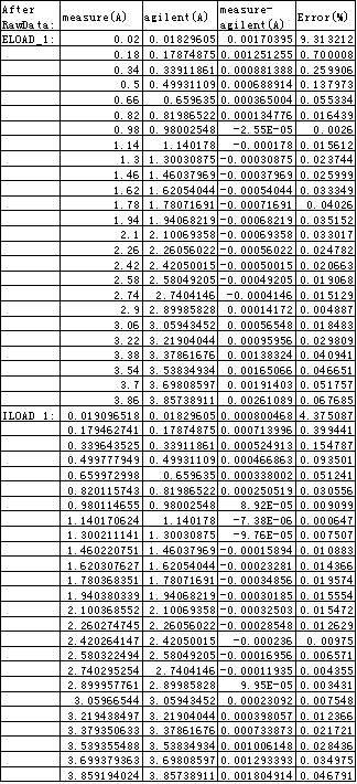
TABLE 3
Furthermore, for the VBUS power source in the power module, the current data measured before the current measurement unit is not calibrated at low current is shown in Table 4.

TABLE 4
The calibration parameters obtained by the calculation of the upper computer are shown in table 5.

TABLE 5
The current measurement unit invokes the calibration parameters and obtains the current measurement results as shown in table 6.

TABLE 6
For the VBUS power source in the power module, the measured current data before calibration of the current measurement unit at high current conditions is shown in Table 7.
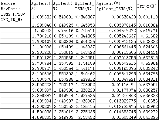
TABLE 7
The calibration parameters calculated by the upper computer are shown in table 8.

TABLE 8
The current measurement unit invokes the calibration parameters and obtains the current measurement results as shown in table 9.

TABLE 9
Through above-mentioned calibration process, the utility model discloses the system is small, with low costs, transplant convenience, integrated simple, and wide to the electric current calibration scope, the calibration back current measurement precision is high, is applicable to consumer electronics product test field.
Claims (6)
1. A current measurement calibration system, characterized by: the system comprises a logic control unit (1), a current measuring unit (2), a storage unit (3) and an upper computer (4), wherein the logic control unit (1) is respectively in communication connection with the current measuring unit (2), the storage unit (3) and the upper computer (4),
the logic control unit (1) is used for receiving an instruction signal from the upper computer (4), collecting a signal of the current measuring unit (2), sending a control signal to the current measuring unit (2), and storing a calibration coefficient into the storage unit (3);
the current measuring unit (2) is used for connecting a product to be measured, supplying power to the product to be measured, receiving signals sent by the logic control unit (1) and the upper computer (4), and sending signals to the logic control unit (1) and the upper computer (4);
the storage unit (3) is used for storing the calibration parameters sent by the logic control unit (1);
the upper computer (4) is used for sending instruction signals to the logic control unit (1), receiving signals uploaded by the logic control unit (1), calculating a calibration coefficient of the system, and sending the calibration coefficient to the storage unit (3) for storage;
the current measuring unit (2) comprises a power supply module (21), a power supply matrix (22), a general calibration board, an instrument interface (23) and a load module (E)-Load), through which the power supply module (21) passes22) To the product to be tested, the load module (E)-Load) and the general calibration board and instrument interface (23), the DAC module of the logic control unit (1) generates a plurality of analog voltages to drive the Load module (E)-Load), the Load module (E)-The Load) generates a constant current Load, the upper computer (4) reads current values through the current measuring unit (2) and a standard instrument connected to the universal calibration board and the instrument interface (23), the upper computer (4) obtains two groups of current values, calibration coefficients are obtained through calculation, the upper computer (4) writes the obtained calibration coefficients into the storage unit (3), and then a power supply passage and a Load passage are selected to carry out current calibration on the current measuring unit (2) by utilizing the calibration coefficients.
2. A current measurement calibration system according to claim 1, wherein: the power module (21) provides VBUS power (211) of the same way and VBATT power (212) of the same way, all is provided with current sensor (213) on the route of two way powers, current sensor (213) convert the electric current on the power route into voltage, and through with ADC module (214) that current sensor (213) are connected measures, ADC module (214) through the SPI bus with logic control unit (1) is connected and the current measurement result of output power.
3. A current measurement calibration system according to claim 2, wherein: the power supply matrix (22) is composed of relays, and the power supply matrix (22) switches whether power supply loops of the VBUS power source (211) and the VBATT power source (212) are connected to the universal calibration board and the instrument interface (23).
4. A current measurement calibration system according to claim 1, wherein: the universal calibration board and instrument interface (23) comprises an MOS (metal oxide semiconductor) tube switching path and an instrument calibration interface, the MOS tube switching path comprises a plurality of channels, and the power module (21) and the instrument calibration interface are alignedLoad module (E)-Load), the instrument calibration interface accesses a current calibration standard instrument.
5. A current measurement calibration system according to claim 1, wherein: the load module (E)-The Load) comprises a plurality of Load channels, a channel selector switch (I _ Load) and a follower amplifier (241), wherein each Load channel comprises a channel DAC (DAC) module (242), a voltage amplifier (243) and a constant current Load (CC _ Eload) which are sequentially connected, the channel DAC module (242) is used for setting the magnitude of Load current, the constant current Load (CC _ Eload) is used for simulating and generating the constant current Load, and the channel selector switch (I _ Load) is used for switching the Load channels.
6. A current measurement calibration system according to claim 5, wherein: the load module (E)-Load) still is connected with Load and switches matrix (25), the opposite side of Load switches matrix (25) is connected with the product that awaits measuring, Load switches matrix (25) and is used for switching different Load passageways and is connected with the product that awaits measuring.
Priority Applications (1)
| Application Number | Priority Date | Filing Date | Title |
|---|---|---|---|
| CN202023071951.8U CN214409261U (en) | 2020-12-18 | 2020-12-18 | Current measurement calibration system |
Applications Claiming Priority (1)
| Application Number | Priority Date | Filing Date | Title |
|---|---|---|---|
| CN202023071951.8U CN214409261U (en) | 2020-12-18 | 2020-12-18 | Current measurement calibration system |
Publications (1)
| Publication Number | Publication Date |
|---|---|
| CN214409261U true CN214409261U (en) | 2021-10-15 |
Family
ID=78039425
Family Applications (1)
| Application Number | Title | Priority Date | Filing Date |
|---|---|---|---|
| CN202023071951.8U Withdrawn - After Issue CN214409261U (en) | 2020-12-18 | 2020-12-18 | Current measurement calibration system |
Country Status (1)
| Country | Link |
|---|---|
| CN (1) | CN214409261U (en) |
Cited By (1)
| Publication number | Priority date | Publication date | Assignee | Title |
|---|---|---|---|---|
| CN112557987A (en) * | 2020-12-18 | 2021-03-26 | 珠海市运泰利自动化设备有限公司 | Current measurement calibration system and method |
-
2020
- 2020-12-18 CN CN202023071951.8U patent/CN214409261U/en not_active Withdrawn - After Issue
Cited By (2)
| Publication number | Priority date | Publication date | Assignee | Title |
|---|---|---|---|---|
| CN112557987A (en) * | 2020-12-18 | 2021-03-26 | 珠海市运泰利自动化设备有限公司 | Current measurement calibration system and method |
| CN112557987B (en) * | 2020-12-18 | 2024-10-11 | 珠海市运泰利自动化设备有限公司 | Current measurement calibration system and method |
Similar Documents
| Publication | Publication Date | Title |
|---|---|---|
| CN112557987B (en) | Current measurement calibration system and method | |
| CN104360165A (en) | Multichannel resistance measuring device | |
| CN103579699B (en) | The calibration steps of cell voltage and device | |
| CN113514168B (en) | Multi-channel temperature sensor testing device | |
| CN117555738B (en) | DPS power supply board for memory FT test | |
| CN108663622A (en) | Battery voltage measuring circuit and voltage measurement system | |
| CN214409261U (en) | Current measurement calibration system | |
| CN114894344A (en) | Temperature sensor calibration circuit, device and system | |
| CN214384610U (en) | Voltage measurement calibration system | |
| CN222599012U (en) | Testing device based on arm model heat flow | |
| CN112187050A (en) | Precise low-cost programmable power supply module for test equipment | |
| CN210835059U (en) | nA-level current measuring system for test equipment | |
| CN218099460U (en) | Power chip testing device | |
| CN112557988A (en) | Voltage measurement calibration system and method | |
| CN114675074B (en) | VDDA correction device and correction method of MCU | |
| CN217467081U (en) | Power panel testing device | |
| CN206695925U (en) | A kind of multichannel RTD thermal resistance measurement modules | |
| CN213342014U (en) | Precise low-cost programmable power supply module for test equipment | |
| CN214205479U (en) | Precise high-voltage attenuation circuit | |
| CN212540524U (en) | Current measurement circuit and equipment applying same | |
| CN211043591U (en) | Handheld tester of intelligent universal circuit breaker | |
| CN114035091A (en) | BMS slave control module single voltage automatic calibration system and method | |
| CN108152776A (en) | A kind of portable digital table characteristic measuring device | |
| CN221281131U (en) | Voltage measurement control circuit | |
| CN223333062U (en) | Multi-channel parameter measurement unit |
Legal Events
| Date | Code | Title | Description |
|---|---|---|---|
| GR01 | Patent grant | ||
| GR01 | Patent grant | ||
| AV01 | Patent right actively abandoned | ||
| AV01 | Patent right actively abandoned | ||
| AV01 | Patent right actively abandoned |
Granted publication date: 20211015 Effective date of abandoning: 20241011 |
|
| AV01 | Patent right actively abandoned |
Granted publication date: 20211015 Effective date of abandoning: 20241011 |