CN213494886U - Lactose sieving device for condensed milk - Google Patents
Lactose sieving device for condensed milk Download PDFInfo
- Publication number
- CN213494886U CN213494886U CN202022506102.4U CN202022506102U CN213494886U CN 213494886 U CN213494886 U CN 213494886U CN 202022506102 U CN202022506102 U CN 202022506102U CN 213494886 U CN213494886 U CN 213494886U
- Authority
- CN
- China
- Prior art keywords
- lactose
- box body
- sides
- box
- vibrating screen
- Prior art date
- Legal status (The legal status is an assumption and is not a legal conclusion. Google has not performed a legal analysis and makes no representation as to the accuracy of the status listed.)
- Active
Links
- GUBGYTABKSRVRQ-QKKXKWKRSA-N Lactose Natural products OC[C@H]1O[C@@H](O[C@H]2[C@H](O)[C@@H](O)C(O)O[C@@H]2CO)[C@H](O)[C@@H](O)[C@H]1O GUBGYTABKSRVRQ-QKKXKWKRSA-N 0.000 title claims abstract description 37
- 239000008101 lactose Substances 0.000 title claims abstract description 37
- 235000020186 condensed milk Nutrition 0.000 title claims abstract description 25
- 238000007873 sieving Methods 0.000 title claims abstract description 18
- 230000006835 compression Effects 0.000 claims abstract description 6
- 238000007906 compression Methods 0.000 claims abstract description 6
- 238000002347 injection Methods 0.000 claims description 15
- 239000007924 injection Substances 0.000 claims description 15
- 230000035939 shock Effects 0.000 claims description 10
- 239000012535 impurity Substances 0.000 claims description 5
- 238000013016 damping Methods 0.000 claims description 4
- 238000007599 discharging Methods 0.000 claims description 4
- XLYOFNOQVPJJNP-UHFFFAOYSA-N water Substances O XLYOFNOQVPJJNP-UHFFFAOYSA-N 0.000 claims description 3
- 239000008187 granular material Substances 0.000 abstract description 7
- 238000001914 filtration Methods 0.000 abstract description 4
- 239000010813 municipal solid waste Substances 0.000 abstract description 4
- 239000000463 material Substances 0.000 abstract description 3
- 238000012216 screening Methods 0.000 abstract description 2
- 239000004744 fabric Substances 0.000 description 8
- 238000000034 method Methods 0.000 description 7
- 239000002245 particle Substances 0.000 description 5
- 238000007664 blowing Methods 0.000 description 2
- 150000002597 lactoses Chemical class 0.000 description 2
- 235000013336 milk Nutrition 0.000 description 2
- 239000008267 milk Substances 0.000 description 2
- 210000004080 milk Anatomy 0.000 description 2
- 235000013361 beverage Nutrition 0.000 description 1
- 238000001035 drying Methods 0.000 description 1
- 235000020251 goat milk Nutrition 0.000 description 1
- 238000004519 manufacturing process Methods 0.000 description 1
- 239000002994 raw material Substances 0.000 description 1
- 229910001220 stainless steel Inorganic materials 0.000 description 1
- 239000010935 stainless steel Substances 0.000 description 1
- 230000001954 sterilising effect Effects 0.000 description 1
- 239000000126 substance Substances 0.000 description 1
Images


Landscapes
- Combined Means For Separation Of Solids (AREA)
Abstract
The utility model discloses a lactose sieving device for condensed milk, which comprises a box body, wherein a feeding funnel is arranged at the top end of the box body, first motors are arranged on two sides of the top end in the box body, scattering blades are symmetrically arranged at the output ends of the first motors, and a vibrating screen with a conical design is arranged below the scattering blades in the box body; the utility model discloses it is rotatory earlier to break up the blade through first motor drive, thereby break up the lactose that adds from feed hopper, make more even of its whereabouts, and then make the lactose distribution on the vibratory screen more even, the phenomenon is piled up to difficult appearance, make it be convenient for sieve, the jet-propelled pipe of rethread second motor drive removes and spouts the vibrating screen through the first air jet of high compression pump drive, thereby in time dredge the sunning mesh when the vibratory screen blocks up, and then guarantee the normal clear of vibratory screen screening work, the large granule material that makes the filtration interception is convenient for take out through setting up the trash removal pipe in the vibratory screen both sides after that, convenience and practicality.
Description
Technical Field
The utility model relates to a condensed milk processing equipment technical field especially relates to a lactose device that sieves for condensed milk.
Background
Condensed milk is a milk product, is a beverage made by sterilizing and concentrating fresh milk or goat milk, and is characterized by being capable of being stored for a long time, the condensed milk can be divided into sugared condensed milk, light condensed milk, defatted condensed milk, semi-defatted condensed milk, flower-colored condensed milk, fortified condensed milk and modulated condensed milk according to different processing raw materials, wherein the sugared condensed milk needs lactose with a specified particle size in the processing process, so that ground lactose particles need to be sieved in the production and processing process of the sugared condensed milk to screen out substances with large particles so as to avoid influencing the quality of subsequent products;
present lactose for condensed milk device that sieves is mostly single structure, the inhomogeneous of lactose granule whereabouts when reinforced leads to falling the lactose on the screen cloth uneven distribution and appearing accumulational phenomenon easily to reduce the efficiency of sieving, and sieve the in-process and block up the screen cloth with the lactose granule that screen cloth aperture size is the same easily, thereby influence the normal clear of work of sieving, the large granule lactose of sieving in-process interception is not convenient for take out in addition, and the practicality is not high, consequently, the utility model provides a lactose for condensed milk device that sieves is used for solving the problem that exists among the prior art.
SUMMERY OF THE UTILITY MODEL
To the above problem, the utility model aims to provide a lactose device that sieves for condensed milk, this lactose device that sieves for condensed milk breaks up the blade rotation through first motor drive earlier, thereby the lactose that will follow feed hopper and add breaks up, make more even of its whereabouts, rethread second motor drive jet-propelled pipe removes and spouts the vibrating screen through the first air jet of high compression pump drive, thereby in time dredge the mesh to shining when vibrating screen blocks up, make the large granule material of filtration interception convenient to take out through arranging the trash discharge pipe in vibrating screen both sides after that.
In order to realize the utility model discloses a purpose, the utility model discloses a following technical scheme realizes: a lactose sieving device for condensed milk comprises a box body, wherein a feeding funnel is arranged at the top end of the box body, first motors are arranged on two sides of the top end inside the box body, dispersing blades are symmetrically arranged at the output ends of the first motors, a vibrating screen with a conical design is arranged below the dispersing blades inside the box body, a vibrating motor is installed on the vibrating screen, impurity discharging pipes are arranged on two sides of the vibrating screen, a baffle plate is arranged below the vibrating screen, a screw rod driven to rotate by a second motor is arranged below the baffle plate, a thread block is sleeved on the screw rod, an air injection pipe in sliding connection with the inner wall of the box body is fixed at the top end of the thread block, a first air injection port is arranged at the top end of the air injection pipe, two sides of the bottom end of the air injection pipe are connected with a high-pressure air pump through elastic hoses, and the high, the bottom end of the box body is provided with a discharge hole.
The further improvement lies in that: the box below is equipped with the shock attenuation seat, the shock attenuation seat inboard is connected with the box through damping spring, shock attenuation seat bottom symmetry is fixed with the supporting leg.
The further improvement lies in that: the first air jet is the equidistance and distributes on the jet-propelled pipe, the intermediate position of both sides all is equipped with the second air jet around the jet-propelled pipe, the second air jet is located same water flat line with the screw rod.
The further improvement lies in that: the gas injection pipe is characterized in that sliding blocks are fixed at two ends of the gas injection pipe, sliding grooves matched with the sliding blocks are formed in the inner walls of two sides of the box body, and the gas injection pipe is connected with the inner wall of the box body in a sliding mode through the sliding blocks.
The further improvement lies in that: and blowing fans are arranged between the vibrating screen and the scattering blades and are symmetrically arranged on the inner walls of the two sides of the box body.
The further improvement lies in that: all install the valve on arranging miscellaneous pipe and the discharge gate, transparent observation window has been seted up on the box.
The utility model has the advantages that: the utility model discloses a box, it is rotatory to break up the blade through first motor drive earlier, thereby break up the lactose that adds from feed hopper, make more even of its whereabouts, and then make the lactose distribution on the vibration screen cloth more even, the phenomenon of piling up is difficult to appear, make it be convenient for sieve, sieving efficiency has been improved to a certain extent, rethread second motor drive jet-propelled pipe removes and spouts the vibration screen cloth through the first jet-propelled mouth of high compression pump drive, thereby in time dredge the sunning mesh when the vibration screen cloth blocks up, and then guarantee the normal clear of vibration screen cloth screening work, large granular material through setting up the trash discharging pipe in vibration screen cloth both sides and making the filtration interception is convenient for take out, convenience and practicality.
Drawings
Fig. 1 is a front view of the present invention;
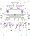
fig. 2 is a cross-sectional view of the present invention;
fig. 3 is a side partial cross-sectional view of the present invention.
Wherein: 1. a box body; 2. a feed hopper; 3. a first motor; 4. scattering leaves; 5. vibrating a screen; 6. a trash removal pipe; 7. a striker plate; 8. a second motor; 9. a screw; 10. a thread block; 11. a gas ejector tube; 12. a first air injection port; 13. an elastic hose; 14. a high pressure air pump; 15. a discharge port; 16. a shock absorbing seat; 17. a damping spring; 18. supporting legs; 19. a second air injection port; 20. a slider; 21. a chute; 22. a blowing fan; 23. a transparent viewing window.
Detailed Description
In order to deepen the understanding of the present invention, the following embodiments will be combined to make the present invention do further details, and the present embodiment is only used for explaining the present invention, and does not constitute the limitation of the protection scope of the present invention.
According to figures 1, 2 and 3, the embodiment provides a lactose sieving device for condensed milk, which comprises a box body 1, wherein a feeding funnel 2 is arranged at the top end of the box body 1, first motors 3 are arranged on two sides of the top end in the box body 1, dispersing blades 4 are symmetrically arranged at the output ends of the first motors 3, a vibrating screen 5 in a conical design is arranged below the dispersing blades 4 in the box body 1, a vibrating motor is arranged on the vibrating screen 5, impurity discharging pipes 6 are arranged on two sides of the vibrating screen 5, a baffle plate 7 is arranged below the vibrating screen 5, a screw rod 9 driven to rotate by a second motor 8 is arranged below the baffle plate 7, a thread block 10 is sleeved on the screw rod 9, an air jet pipe 11 in sliding connection with the inner wall of the box body 1 is fixed at the top end of the thread block 10, a first air jet port 12 is arranged at the top end of the air jet pipe 11, both sides of the bottom end of the air injection pipe 11 are connected with a high-pressure air pump 14 through an elastic hose 13, the high-pressure air pump 14 is located at the lower part of two side walls of the box body 1, and a discharge hole 15 is formed in the bottom end of the box body 1.
The box body 1 below is equipped with shock attenuation seat 16, the shock attenuation seat 16 inboard is connected with box body 1 through damping spring 17, 16 bottom symmetries of shock attenuation seat are fixed with supporting leg 18.
The two ends of the gas injection pipe 11 are both fixed with sliding blocks 20, sliding grooves 21 matched with the sliding blocks 20 are formed in the inner walls of the two sides of the box body 1, and the gas injection pipe 11 is connected with the inner wall of the box body 1 in a sliding mode through the sliding blocks 20.
A blowing-off fan 22 is arranged between the vibrating screen 5 and the scattering blades 4, and the blowing-off fan 22 is symmetrically arranged on the inner walls of two sides of the box body 1.
All install the valve on arranging miscellaneous pipe 6 and the discharge gate 15, set up transparent observation window 23 on the box 1, be convenient for observe the condition of sieving.
When lactose is required to be sieved in the condensed milk processing process, a first motor 3 is started to drive a dispersing blade 4 to rotate, then the ground lactose is added into a box body 1 from a feeding hopper 2, then a dispersing fan 22 is started, the lactose is firstly dispersed by the dispersing blade 4 and then is blown by the dispersing fan 22 so as to uniformly fall on a vibrating screen 5, then the vibrating screen 5 is started to drive the lactose to vibrate and sieve, the lactose with qualified particle size falls through a baffle plate 7 and is discharged through a discharge port 15 in the sieving process, then the discharged lactose is collected and stored through a sealed stainless steel tank, finally the lactose with overlarge particle size on the vibrating screen 5 is discharged through an impurity discharge pipe 6, when the vibrating screen 5 is blocked in the vibrating and sieving process, a second motor 8 is started firstly to drive a screw rod 9 to rotate, a thread block 10 on the screw rod 9 drives an air injection pipe 11 to move, and a high-pressure air pump 14 is started to convey air in the air injection pipe 11 at the same time, so that the clogged screen openings are unclogged by the high-pressure gas ejected through the first gas ejection openings 12.
This lactose device that sieves for condensed milk, the power distribution box comprises a box body 1, it is rotatory to break up 4 blades through the drive of first motor 3 earlier, thereby break up the lactose that will follow feed hopper 2 and add, make more even of its whereabouts, and then make the lactose distribution on the vibrating screen 5 more even, the phenomenon is piled up to difficult appearance, make it be convenient for sieve, sieving efficiency has been improved to a certain extent, rethread second motor 8 drive jet-propelled pipe 11 removes and spouts vibrating screen 5 through high compression pump 14 drive first jet-propelled mouth 12, thereby in time to drying in the sun the mesh when vibrating screen 5 blocks up and dredge, and then guarantee vibrating screen 5 normal clear of work, make the large granule material of filtering the interception convenient to take out through setting up impurity discharge pipe 6 in vibrating screen 5 both sides, and convenient and practical.
The foregoing illustrates and describes the principles, general features, and advantages of the present invention. It will be understood by those skilled in the art that the present invention is not limited to the above embodiments, and that the foregoing embodiments and descriptions are provided only to illustrate the principles of the present invention without departing from the spirit and scope of the present invention. The scope of the invention is defined by the appended claims and equivalents thereof.
Claims (6)
1. The utility model provides a condensed milk is with lactose device that sieves, includes box (1), its characterized in that: the box body (1) top is provided with a feeding funnel (2), both sides of the top end inside the box body (1) are provided with a first motor (3), the output end of the first motor (3) is symmetrically provided with scattering blades (4), the lower part of the inside of the box body (1) located at the scattering blades (4) is provided with a vibrating screen (5) with a conical design, the vibrating screen (5) is provided with a vibrating motor, both sides of the vibrating screen (5) are provided with impurity discharging pipes (6), a baffle plate (7) is arranged below the vibrating screen (5), the lower part of the baffle plate (7) is provided with a screw rod (9) which is driven to rotate by a second motor (8), the upper thread of the screw rod (9) is sleeved with a thread block (10), the top end of the thread block (10) is fixed with an air jet pipe (11) which is in sliding connection with the inner wall of the box body (1), the top end of the air jet pipe, the air injection pipe (11) bottom both sides all are connected with high compression pump (14) through elastic hose (13), high compression pump (14) are located the lower part position of box (1) both sides wall, box (1) bottom is equipped with discharge gate (15).
2. A lactose sieving apparatus as claimed in claim 1, wherein: the box (1) below is equipped with shock attenuation seat (16), shock attenuation seat (16) inboard is connected with box (1) through damping spring (17), shock attenuation seat (16) bottom end symmetry is fixed with supporting leg (18).
3. A lactose sieving apparatus as claimed in claim 1, wherein: first air jet (12) are the equidistance and distribute on jet (11), the intermediate position of both sides all is equipped with second air jet (19) around jet (11), second air jet (19) are located same water flat line with screw rod (9).
4. A lactose sieving apparatus as claimed in claim 1, wherein: both ends of the jet pipe (11) are fixed with sliding blocks (20), sliding grooves (21) matched with the sliding blocks (20) are formed in the inner walls of the two sides of the box body (1), and the jet pipe (11) is connected with the inner wall of the box body (1) in a sliding mode through the sliding blocks (20).
5. A lactose sieving apparatus as claimed in claim 1, wherein: be equipped with between vibrating screen (5) and break up blade (4) and blow off fan (22), blow off fan (22) symmetry is installed in the both sides inner wall of box (1).
6. A lactose sieving apparatus as claimed in claim 1, wherein: all install the valve on arranging miscellaneous pipe (6) and discharge gate (15), transparent observation window (23) have been seted up on box (1).
Priority Applications (1)
| Application Number | Priority Date | Filing Date | Title |
|---|---|---|---|
| CN202022506102.4U CN213494886U (en) | 2020-11-03 | 2020-11-03 | Lactose sieving device for condensed milk |
Applications Claiming Priority (1)
| Application Number | Priority Date | Filing Date | Title |
|---|---|---|---|
| CN202022506102.4U CN213494886U (en) | 2020-11-03 | 2020-11-03 | Lactose sieving device for condensed milk |
Publications (1)
| Publication Number | Publication Date |
|---|---|
| CN213494886U true CN213494886U (en) | 2021-06-22 |
Family
ID=76420178
Family Applications (1)
| Application Number | Title | Priority Date | Filing Date |
|---|---|---|---|
| CN202022506102.4U Active CN213494886U (en) | 2020-11-03 | 2020-11-03 | Lactose sieving device for condensed milk |
Country Status (1)
| Country | Link |
|---|---|
| CN (1) | CN213494886U (en) |
Cited By (2)
| Publication number | Priority date | Publication date | Assignee | Title |
|---|---|---|---|---|
| CN114471810A (en) * | 2022-02-10 | 2022-05-13 | 新沂市砥研医药技术研究院有限公司 | A kind of automatic crushing equipment for the recycling and reuse of vials |
| CN114570513A (en) * | 2022-03-07 | 2022-06-03 | 江西和盈药业有限公司 | Device and method for grinding raw materials in pulse-activating decoction oral liquid |
-
2020
- 2020-11-03 CN CN202022506102.4U patent/CN213494886U/en active Active
Cited By (3)
| Publication number | Priority date | Publication date | Assignee | Title |
|---|---|---|---|---|
| CN114471810A (en) * | 2022-02-10 | 2022-05-13 | 新沂市砥研医药技术研究院有限公司 | A kind of automatic crushing equipment for the recycling and reuse of vials |
| CN114570513A (en) * | 2022-03-07 | 2022-06-03 | 江西和盈药业有限公司 | Device and method for grinding raw materials in pulse-activating decoction oral liquid |
| CN114570513B (en) * | 2022-03-07 | 2022-08-12 | 江西和盈药业有限公司 | Device and method for grinding raw materials in pulse-activating decoction oral liquid |
Similar Documents
| Publication | Publication Date | Title |
|---|---|---|
| CN103521452B (en) | A kind of environment-friendly type compound grain cleaner | |
| CN213494886U (en) | Lactose sieving device for condensed milk | |
| CN210545297U (en) | Device special for rice finish machining | |
| CN109569897A (en) | A kind of building waste screening plant | |
| CN205518535U (en) | A raw material handling sieve for feed processing production | |
| CN119610484A (en) | Environment-friendly PET bottle piece breaker | |
| CN115430607B (en) | Impurity removing device for rice processing | |
| CN208288422U (en) | Vibrating screen is used in a kind of screening of low-smoke halogen-free cable particulate material | |
| CN208990749U (en) | A kind of discharging mechanism on wet mixing pelletizer | |
| CN208407285U (en) | Pulverize unit | |
| CN114632609B (en) | Broken washing recovery production line of metal oil drum and engine oil check | |
| CN204620432U (en) | A kind of accurate seed aidr bells blast system | |
| CN208679312U (en) | A kind of raw material grinding device | |
| CN212597127U (en) | Sieving mechanism for agricultural product processing | |
| CN213700215U (en) | Pomace feed production line | |
| CN108772284A (en) | Sandstone production system | |
| CN210701121U (en) | Concrete vibrates separation sieve | |
| CN211964482U (en) | Special ceramic refining equipment | |
| CN107824458A (en) | A kind of grains separating machine of multistage pneumatic separation | |
| CN115634761A (en) | A kind of jet mill for silver powder production | |
| CN222833660U (en) | Discharging device and vibration screening system | |
| CN207746120U (en) | A kind of grains separating machine of multistage pneumatic separation | |
| CN206661361U (en) | A kind of efficient dedusting type whole grain device | |
| CN208494880U (en) | A kind of novel foodstuff barrel cleaning sieve | |
| CN215902197U (en) | Fodder powder cleaning sieve |
Legal Events
| Date | Code | Title | Description |
|---|---|---|---|
| GR01 | Patent grant | ||
| GR01 | Patent grant |