SUMMERY OF THE UTILITY MODEL
To the not enough of above-mentioned prior art, the utility model aims to solve the technical problem that: how to provide
In order to solve the technical problem, the utility model discloses a following technical scheme: the utility model provides a tent convenient to expand, includes tent top, umbrella stick, its characterized in that: umbrella support ribs are uniformly arranged on the top of the tent, the umbrella support ribs are unfolded in an umbrella shape, tent cloth covers the umbrella support ribs, one ends of the umbrella support ribs are concentrated at the umbrella rod, and one ends of the umbrella support ribs, far away from the umbrella rod, are provided with connecting pieces; the umbrella rod is provided with a spring and a switch; the umbrella is characterized by further comprising an enclosure awning, wherein the enclosure awning comprises an operation box, a threaded rod and a supporting rod, and the outer top end of the operation box is rotatably connected with the bottom end of the umbrella rod; the top end in the operation box is rotationally connected with the upper end of the threaded rod, and the lower end of the threaded rod penetrates through the bottom of the operation box and extends to the outside and is connected with a base through a bearing; a driven bevel gear is arranged on the threaded rod and positioned in the operation box, a driving bevel gear is externally meshed with the driven bevel gear, the driving bevel gear is connected with a rotating shaft, and a rotating disc is connected to one end, far away from the driving bevel gear, of the rotating shaft; the threaded rod is further rotatably connected with a threaded sleeve, a movable rod is evenly hinged to the radial circumference of the horizontal threaded sleeve, one end, away from the threaded sleeve, of the movable rod is hinged to the lower end of the supporting rod, and the upper end of the supporting rod is connected with the umbrella supporting rib through the connecting piece.
The working principle of the scheme;
when the tent needs to be unfolded and installed, the base is fixed at the place where the tent needs to be installed, and then the umbrella support ribs are unfolded like an umbrella through the springs and the switches on the umbrella rods, so that a ceiling is formed; then, rotating the turntable, wherein the turntable drives the rotating shaft to rotate, the rotating shaft drives the driving bevel gear to rotate, the driving bevel gear drives the driven bevel gear to rotate, the driven bevel gear drives the threaded rod to rotate, and the threaded rod rotates to drive the threaded sleeve to move downwards; because the threaded sleeve is evenly hinged with the movable rod, and then one end of the movable rod, which is far away from the threaded sleeve, is hinged with the supporting rod, the movable rod and the supporting rod can be slowly unfolded, after the threaded sleeve rotates to the chassis, the supporting rod and the threaded rod are parallel to each other, and after the movable rod and the supporting rod are perpendicular to each other, the enclosure is unfolded; then the tent is unfolded after the umbrella branch ribs are connected with the supporting rods through the connecting pieces by operating the connecting pieces on the umbrella branch ribs.
The beneficial effect of this scheme:
the tent roof is quickly opened like an umbrella, then the enclosure tent can be directly unfolded by rotating the rotary disc of the operation box, and then the tent roof and the enclosure tent are connected through the connecting piece, so that the whole tent is unfolded, and the problems that the existing tent is multiple in parts, complicated in assembly steps and inconvenient to unfold and install are solved; the position of the umbrella supporting rib can be adjusted when the operating box is connected with the bottom end of the umbrella rod in a rotating mode, so that the umbrella supporting rib is more easily corresponding to the supporting rod, and the operating box is convenient to connect.
Detailed Description
The present invention will be described in further detail with reference to the accompanying drawings.
In the specific implementation: as shown in fig. 1 to 6, a tent convenient to unfold comprises a tent roof 1 and an umbrella rod 3, wherein umbrella support ribs 2 are uniformly arranged on the tent roof 1, the umbrella support ribs 2 are unfolded like an umbrella, tent cloth covers the umbrella support ribs 2, one ends of the umbrella support ribs 2 are concentrated at the umbrella rod 3, one ends of the umbrella support ribs 2, which are far away from the umbrella rod 3, are provided with connecting pieces, and the umbrella rod 3 is provided with a spring and a switch;
the umbrella is characterized by further comprising an enclosure awning, wherein the enclosure awning comprises an operation box 4, a threaded rod 5 and a supporting rod 11, and the outer top end of the operation box 4 is rotatably connected with the bottom end of the umbrella rod 3; the top end in the operation box 4 is rotationally connected with the upper end of the threaded rod 5, and the lower end of the threaded rod 5 penetrates through the bottom of the operation box 4 to extend to the outside and is connected with a base through a bearing; a driven bevel gear 6 is arranged on the threaded rod 5 and in the operation box 4, a driving bevel gear 7 is externally meshed on the driven bevel gear 6, the driving bevel gear 7 is connected with a rotating shaft, and a rotating disc 8 is connected to one end, far away from the driving bevel gear 7, of the rotating shaft; threaded rod 5 is last still to rotate and to be connected with thread bush 9, 9 horizontal radial week of thread bush evenly articulate there is the movable rod 10, the movable rod 10 keep away from the one end of thread bush 9 with the bracing piece 11 lower extreme is articulated, and 11 upper ends of bracing piece pass through with umbrella bone 2 the connecting piece is connected.
The working principle of the scheme;
when the tent needs to be unfolded and installed, the base is firstly fixed at the place where the tent needs to be installed, then the switch on the umbrella rod 3 is pressed, and the umbrella support ribs 2 are unfolded like an umbrella through the matching of the spring and the sliding sleeve 9, so that a ceiling is formed; then, the rotating disc 8 is rotated, the rotating disc 8 drives the rotating shaft to rotate, the rotating shaft drives the driving bevel gear 7 to rotate, the driving bevel gear 7 drives the driven bevel gear 6 to rotate, the driven bevel gear 6 drives the threaded rod 5 to rotate, and the threaded rod 5 rotates to drive the threaded sleeve 9 to move downwards; because the threaded sleeve 9 is evenly hinged with the movable rod 10, and then one end of the movable rod 10, which is far away from the threaded sleeve 9, is hinged with the supporting rod 11, the movable rod 10 and the supporting rod 11 can be slowly unfolded, after the threaded sleeve 9 rotates to the chassis, the supporting rod 11 and the threaded rod 5 are parallel to each other, and after the movable rod 10 and the supporting rod 11 are perpendicular to each other, the enclosure tent is unfolded; then, the umbrella ribs 2 are connected with the support rods 11 through the connecting pieces by operating the connecting pieces on the umbrella ribs 2, and then the tent is unfolded.
The beneficial effect of this scheme:
the tent top 1 is quickly opened like an umbrella, then the enclosure tent can be directly unfolded by rotating the rotary disc 8 of the operation box 4, and then the tent top 1 and the enclosure tent are connected through the connecting piece, so that the whole tent is unfolded, and the problems of multiple parts, complex assembly steps and inconvenience in unfolding and installation of the existing tent are solved; the outer top end of the operation box 4 is rotatably connected with the bottom end of the umbrella rod 3, so that the position of the umbrella support rib 2 can be adjusted when the operation box is installed, the umbrella support rib 2 is easier to correspond to the support rod 11, and the connection is convenient.
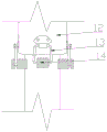
The connecting piece is a sleeve 12 with a downward opening, a buckle 13 is arranged on the outer side of the sleeve 12 in the horizontal radial circumference, and clamping seats 14 are uniformly arranged on the upper end of the supporting rod 11 in the horizontal radial circumference; the inner circle diameter of the sleeve 12 is larger than that of the support rod 11.
Because the inner circle diameter of the sleeve 12 is larger than that of the supporting rod 11, when the supporting rod 11 is connected with the umbrella supporting framework 2, the upper end of the supporting rod 11 is inserted into the sleeve 12 and then connected with the clamping seat 14 through the buckle 13, and the ceiling and the enclosure are more tightly connected.
Wherein, still include powerful magnet, the bracing piece 11 upper end, top in the sleeve 12, the thread bush 9 bottom and the base top are provided with respectively powerful magnet.
When the threaded sleeve 9 rotates to the top end of the base plate, the bottom end of the threaded sleeve 9 and the top end of the base can be mutually adsorbed through a strong magnet, and the upper end of the stay bar can also be mutually adsorbed with the inner top of the sleeve 12 after being inserted into the sleeve 12; therefore, the stability and the safety of the tent can be further improved.
Wherein, still include gas spring 15, one end of gas spring 15 sets up on the movable rod 10, the other end of gas spring 15 sets up on bracing piece 11.
The gas spring 15 can fix the support rod 11 and the movable rod 10 after the enclosure is unfolded, so as to prevent the accidental contraction between the support rod 11 and the movable rod 10; stability of the tent after further deployment.
The fixing piece comprises a threaded pipe 16, a rotary seat 17 and a handle, one end of the threaded pipe 16 is connected with the rotary seat 17, and the rotary seat 17 is disc-shaped and is eccentrically connected with the handle at the top end.
When the tent is completely unfolded, the threaded pipe 16 is rotatably fixed in the ground by rotating the handle, so that the support pole 11 is more stable.
Wherein, a drill bit is arranged on one end of the threaded pipe 16 far away from the rotary seat 17.
The tent can be installed by being turned over to the ground through the drill bit in a place where the ground is hard, and the practicability of the tent is higher.
Wherein, still include the tarpaulin, the tarpaulin sets up on movable rod 10 and bonds through magic subsides.
The waterproof cloth is more convenient to install by being pasted through the magic tape.
Wherein, still include dampproofing pad, dampproofing pad covers on the tarpaulin.
The moisture resistance and the adaptability of the tent are improved.
Wherein, the utility model also comprises a shielding cloth which is arranged between the support rods 11 and is provided with a zipper 18.
Wherein, the tent cloth is provided with a ventilation window 20, and the shielding cloth is provided with an observation window 19.
The above is only a preferred embodiment of the present invention, and it should be noted that, for those skilled in the art, various changes and modifications can be made without departing from the technical scope of the present invention, and the technical scope of the present invention is also considered to fall into the scope of the claims.