CN212735863U - Hydraulic steel rail plug nail puller - Google Patents
Hydraulic steel rail plug nail puller Download PDFInfo
- Publication number
- CN212735863U CN212735863U CN202021042378.5U CN202021042378U CN212735863U CN 212735863 U CN212735863 U CN 212735863U CN 202021042378 U CN202021042378 U CN 202021042378U CN 212735863 U CN212735863 U CN 212735863U
- Authority
- CN
- China
- Prior art keywords
- oil
- clamping plate
- hydraulic
- shell
- rail plug
- Prior art date
- Legal status (The legal status is an assumption and is not a legal conclusion. Google has not performed a legal analysis and makes no representation as to the accuracy of the status listed.)
- Expired - Fee Related
Links
Images


Landscapes
- Portable Nailing Machines And Staplers (AREA)
Abstract
The utility model relates to a fluid pressure type rail plug pin pull-out ware, it includes power part, first casing and end cover, power part arranges in and link firmly in the first casing, the end cover links firmly with first casing, and its characteristics are: the hydraulic cylinder of the pulling component is arranged in the second shell and fixedly connected with the second shell, the fixed clamping plate of the pulling component is fixedly connected with the second shell, and the hydraulic cylinder of the pulling component is communicated with the power component through the oil delivery hose. When the hydraulic oil extraction device works, the stop valve of the oil return channel is closed, the movable clamping plate of the extraction component is close to the steel rail, the movable clamping plate and the fixed clamping plate of the extraction component are placed at the neck of the steel rail plug pin, the swing handle pulls the plunger of the oil pump to move in a reciprocating mode, hydraulic oil is injected into the hydraulic cylinder of the extraction component, the hydraulic oil drives the piston rod to extend out, and the distance between the movable clamping plate and the fixed clamping plate is gradually increased until the steel rail plug pin is extracted.
Description
Technical Field
The utility model relates to a railway maintenance tool, concretely relates to rail plug pin of railway station inside and between section track circuit equipment plays to pull out is a fluid pressure type rail plug pin pull-out ware.
Background
The guide wire, the jumper wire, the box connecting wire and the like connected between the track circuit steel rails in the railway station and between the sections are connected by steel rail plug nails, the steel rail plug nails and plug nail holes are in knocking contact with steel conical surfaces, the contact is very tight, the operation space is limited, tools need to be replaced for use in a matched mode, and the operation cannot be performed when special narrow and small spaces exist. The existing pulling tools are divided into 4 types:
1. when the operation space is large, the hammer and the punch are used for beating forcefully by manpower. There are problems: the hammer type is 4 pounds, the weight is 1.5 kilograms, the punch length is 20 centimeters, the diameter is 20 millimeters, and the weight of the quenched hexagonal steel is 0.5 kilogram. When the flat-headed hammer is used for knocking, the large surface of the flat-headed hammer is in contact with the small surface of the punch, the requirement on the operability of operators is extremely high, and the hand slightly deviating to hold the punch can be injured by crashing, so that personal injury is easily caused. The punch is made of quenched steel, and the field operation often generates over-violent force, generates fracture, and splashes steel blocks to hurt people. The operation space is small and cannot be used;
2. when the operation space is small, a crowbar is used for pulling out the steel pipe by utilizing the lever principle. There are problems: the crowbar has the advantages that the total length is 1.5-0.8 meter, the weight is 5-11 kilograms, the nail pulling part needs to be specially customized and is not durable, the weight is larger, the crowbar is not easy to carry, and the crowbar is rarely used in operation. When the plug nail is pulled out, the plug nail needs to be perpendicular to the ground, the plug nail drops off instantly, and operators are easy to slip and fall down. When the contact of the plug nail is too deep, the space of the nail pulling part is insufficient and the plug nail can not be used;
3. mechanical screw plug pin extractor. There are problems: the length is 33 cm, the weight is 3 kg, the internal screw rod part has dense and small threads, is not durable and is easy to damage, a 300MM wrench needs to be carried for rotation during operation, the operation speed is slow and labor is wasted, the number of carrying tools is increased, the length is long, the weight is heavy, the carrying is difficult, and the field operation is basically not used;
4. a hydraulic plug pin extractor. There are two types: the device is respectively a right angle and a full-length integrated type, wherein (1) the right angle is L-shaped, the length of an operable surface is 21 cm, and the weight is 4.5 kg. (2) Typically, the monolith is 55 cm in length and weighs 4.5 kg. The two types of pulling-out devices have the same principle, and are pressurized by a manual oil pump, so that the oil cylinder acts to jack the plug nail through the pulling-out part. There are problems: the weight is heavier, the size is large, the universal use cannot be realized due to the limitation of the operation space during operation, and the pulling weight is 8 tons.
Summary the above tools present common problems: (1) the size is too long or too large, and the universal capability cannot be achieved due to the limitation of the operation space. (2) The mechanical strength is insufficient and the product is easy to damage. (3) Heavy, bulky and not easy to carry. (4) The operability is strong, the operation requirement is high, and the requirement of simplicity, convenience and quickness cannot be met. (5) The safety factor is low, and personal injury is caused.
Disclosure of Invention
The utility model discloses the technical problem that will solve is: overcomes the defects of the prior art and provides a hydraulic steel rail plug nail extractor.
The utility model provides a technical problem's scheme is: the utility model provides a hydraulic pressure type rail plug pin extractor, it includes power part, first casing and end cover, power part is hydraulic control device, and power part arranges in first casing links firmly, the end cover links firmly characterized by with first casing: the hydraulic cylinder of the pulling component is arranged in the second shell and fixedly connected, the fixed clamping plate of the pulling component is fixedly connected with the second shell, and the overflowing hole of the hydraulic cylinder of the pulling component is communicated with the oil conveying hole of the power component through the oil conveying hose.
The pull-up component comprises a hydraulic cylinder, a fixed clamping plate, a movable clamping plate, a reset plate and a reset spring, the hydraulic cylinder is arranged in the second shell, a piston rod downwards extends out of the second shell, a cylinder body of the hydraulic cylinder is fixedly connected with the second shell, an overflowing hole extends out of the second shell, the fixed clamping plate is sleeved on the piston rod and is in sliding connection, and the upper end of the fixed clamping plate is fixedly connected with the second shell.
Decide the grip block and be right trapezoid's flat board for the cross-section, decide the centre of grip block and set up big through-hole, the cross-section is right trapezoid's decides grip block, the hypotenuse of its one side is for can getting into the first inclined plane between rail and the rail plug nail, sets up the first open slot that is used for centre gripping rail plug nail neck in the middle of first inclined plane, in first inclined plane, the bottom of first open slot sets up the facet for hold the rail plug nail, the bottom surface of deciding the grip block, its front end and rear end set up two parallel logical grooves, and logical groove one side that corresponds with first inclined plane sets up ascending second inclined plane, and the second inclined plane intersects with first inclined plane and forms the breach of stepping down.
A small through hole is arranged in the middle of the movable clamping plate, and the position of the small through hole corresponds to the position of the large through hole of the fixed clamping plate; a second opening groove for clamping the neck of the steel rail plug pin is arranged on the left side or the right side of the movable clamping plate, and the position and the shape of the second opening groove are consistent with those of the first opening groove of the fixed clamping plate; two parallel first bosses are arranged on the top surface, the front end and the rear end of the movable clamping plate, and the positions and the shapes of the first bosses correspond to those of the through grooves of the fixed clamping plate; and a second boss with a triangular section is arranged on one side of the first boss corresponding to the second open slot, the two bevel edges of the second boss with the triangular section are respectively a third bevel and a fourth bevel, and the positions and the shapes of the third bevel and the fourth bevel of the second boss correspond to the first bevel and the second bevel of the fixed clamping plate.
The power part includes oil tank, blanking cover, the fixed body, oil pump, first check valve, second check valve, stop valve, handle and knob, in the first casing was arranged in to the oil tank, outside the oil filler point of oil tank stretched out first casing, the oil filler point by the blanking cover shutoff, the side of oil tank is arranged in to the fixed body, in the fixed body was arranged in to the oil pump, the plunger of oil pump passed the fixed body and stretched out outside first casing, the oil inlet of oil pump passed through the oil feed passageway and the oil tank intercommunication of the fixed body, the oil-out of oil pump and the passageway intercommunication of producing oil of the fixed body, first check valve was arranged in the oil feed passageway of the fixed body, the second check valve was arranged in the passageway of producing oil of the fixed body, the stop valve was arranged in the oil return passageway of the fixed body, and the control rod passed the fixed body and stretched out outside the first casing, outside the first casing was arranged in to the handle, the plunger top of oil pump, the rear end is an operating handle, the middle part is hinged with the plunger piston, and the knob is arranged outside the first shell and at the operating rod of the stop valve and fixedly connected.
The oil pump fixing device is characterized in that the fixing body is a cylinder, one side, close to the oil tank, of the fixing body is provided with an accommodating cavity for accommodating an oil pump, a main channel is arranged at the center of the side face of the accommodating cavity and the center of the fixing body, an oil inlet channel and an oil outlet channel are respectively arranged at the bottom of the accommodating cavity, the oil inlet channel is communicated with the oil tank, the oil outlet channel is communicated with the main channel, an oil return channel is arranged at the side face of the accommodating cavity, and one end of the oil return channel.
The oil pump is a plunger pump.
The utility model discloses a use method is: rotating the knob to close the stop valve of the oil return passage, adjusting the movable clamping plate of the pulling part to be upwards contacted with the fixed clamping plate, enabling the movable clamping plate of the pulling part to be close to the steel rail, placing a first open slot and a second open slot which are formed by the movable clamping plate and the fixed clamping plate of the pulling part into the neck of the steel rail plug nail between the steel rail and the steel rail plug nail, swinging the handle, pulling a plunger of an oil pump to reciprocate through the handle to inject hydraulic oil into a hydraulic cylinder of the pulling part, driving a piston to stretch out through the hydraulic oil, enabling the fixed clamping plate to move in the opposite direction of the movement of the piston due to the fact that the movable clamping plate leans against the steel rail, and gradually increasing the distance between the movable clamping plate and the fixed clamping plate until the steel rail plug.
The utility model has the advantages that:
1 the utility model discloses a pull-out ware has carried out preferential improvement to current pull-out ware shortcoming, and power unit uses hydraulic control device, and power unit and pull-out adopt the oil hose to carry out the flexible coupling between the part, can fold or the components of a whole that can function independently carries. The weight is reduced, compared with the pulling device in the prior art, the volume is reduced to 25 cm on the whole, the weight is reduced to 3.3 kg, the pulling height is increased by 3 cm, and the pulling weight is 10 tons;
2 the puller of the utility model can be suitable for pulling steel rail plug nails in special and narrow operation space, the steel rail plug nails in special and narrow operation space are found in the test, the operation space is 14 cm, the pulling part is 12 cm, and the operation requirement can be completely met;
3 the puller of the utility model can be used for installing new plug nails, and when installing new steel rail plug nails, the new steel rail plug nails can be jacked into the steel rail by utilizing the characteristic that the oil cylinder stretches out by 5 cm, thereby realizing the function of both pulling nails and ingot nails;
4 the utility model discloses a puller is small and exquisite, nimble, and easy operation does not receive the operating space restriction, can 360 degrees rotations, buckle the use, and large-scale station crossover switch, the movable point switch of speeding, the pulling plug nail work of marshalling yard trouble district position, special narrow and small space all can not be restricted, has realized general function completely, and the disposable does not need the maintenance throughout, and it is convenient to maintain.
The folding portable folding chair has the advantages of being small, flexible, light in weight, capable of being disassembled, folded, convenient to carry, adaptable to various space, strong in universality, time-saving, labor-saving, high in efficiency, convenient to maintain and long in service life.
Drawings
Fig. 1 is a schematic structural view of a hydraulic rail plug nail extractor of the present invention;
FIG. 2 is a schematic cross-sectional view of a hydraulic rail plug nail extractor;
FIG. 3 is a schematic sectional view A-A of FIG. 2;
FIG. 4 is a schematic cross-sectional view B-B of FIG. 2;
FIG. 5 is a schematic cross-sectional view C-C of FIG. 2;
FIG. 6 is a schematic cross-sectional view of a hydraulic rail plug pin extractor according to the present invention, with the fixed clamping plate and the movable clamping plate removed from the extracting member;
FIG. 7 is a schematic left side cross-sectional view of FIG. 6;
FIG. 8 is a schematic front view of a fixed clamping plate of the hydraulic rail plug nail extractor of the present invention;
FIG. 9 is a left side schematic view of FIG. 8;
FIG. 10 is a top view of FIG. 8;
FIG. 11 is a schematic cross-sectional view D-D of FIG. 10;
fig. 12 is a schematic front view of a movable clamping plate of the hydraulic rail plug nail extractor of the present invention;
FIG. 13 is a left side schematic view of FIG. 12;
FIG. 14 is a top view of FIG. 12;
FIG. 15 is a schematic cross-sectional view E-E of FIG. 14;
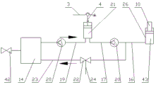
fig. 16 is a schematic view of a hydraulic system of the hydraulic rail plug nail extractor of the present invention.
In the figure: 1 blanking cover, 2 power parts, 3 handles, 4 plungers, 5 lugs, 6 end covers, 7 oil delivery hoses, 8 knobs, 9 pulling parts, 10 piston rods, 11 movable clamping plates, 12 fixed clamping plates, 13 first shells, 14 oil tanks, 15 fixed bodies, 16 main channels, 17 oil outlet channels, 18 second one-way valves, 19 oil inlet channels, 20 first one-way valves, 21 oil pumps, 22 stop valves, 23 oil return channels, 24 operating rods, 25 second shells, 26 cylinder bodies, 27 return springs, 28 return plates, 29 overflowing holes, 30 second inclined planes, 31 first inclined planes, 32 through grooves, 33 first open grooves, 34 small planes, 35 large through holes and 36 gaps, 37 first boss, 38 fourth slope, 39 third slope, 40 second open slot, 41 small through hole, 42 valve, 43 valve.
Detailed Description
The present invention will be further explained with reference to the drawings and examples.
Referring to fig. 1 to 16, in embodiment 1, a hydraulic rail plug nail extractor includes a power component 2, a first housing 13 and an end cover 6, where the power component 2 is a hydraulic control device, the power component 2 is disposed in the first housing 13 and is fixedly connected thereto, a layer of soft rubber is coated on an outer circumferential surface of one end of the first housing 13 close to the plug cover 1, the end cover 6 is fixedly connected to the first housing 13, the hydraulic rail plug nail extractor further includes a pull component 9, a second housing 25 and an oil hose 7, a hydraulic cylinder 43 of the pull component 9 is disposed in the second housing 25 and is fixedly connected thereto, a fixed clamping plate 12 of the pull component 9 is fixedly connected to the second housing 25, an overflow hole 29 of the hydraulic cylinder 43 of the pull component 9 is communicated with an oil delivery hole of the power component 2 through the oil hose 7, and the oil hose 7 is a high-pressure hose.
The pulling component 9 comprises a hydraulic cylinder 43, a fixed clamping plate 12, a movable clamping plate 11, a reset plate 28 and a reset spring 27, wherein the hydraulic cylinder 43 is arranged in the second shell 25, the piston rod 10 extends downwards out of the second shell 25, a cylinder body 26 of the hydraulic cylinder 43 is fixedly connected with the second shell 25, and an overflowing hole 29 extends out of the second shell 25, the fixed clamping plate 12 is sleeved on the piston rod 10 and is in sliding connection, the upper end of the fixed clamping plate is fixedly connected with the second shell 25, the movable clamping plate 11 is arranged below the fixed clamping plate 12 and at the end of the piston rod 10 and is fixedly connected with the piston rod, the reset plate 28 is arranged in the second shell 25, is sleeved on the piston rod 10 and is fixedly connected with the piston rod 10, the reset spring 27 is arranged between the second shell 25 and the hydraulic cylinder 43, the upper end of the reset spring 27 is fixedly connected with the second shell 25.
Decide grip block 12 and be the flat board that the cross-section is right trapezoid, decide the centre of grip block 12 and set up big through-hole 35, the cross-section is right trapezoid decides grip block 12, the hypotenuse of its one side is for getting into the first inclined plane 31 between rail and the rail jam nail, set up the first open slot 33 that is used for centre gripping rail jam nail neck in the middle of first inclined plane 31, in first inclined plane 31, the bottom of first open slot 33 sets up facet 34 for holding the rail jam nail, the bottom surface of deciding grip block 12, its front end and rear end set up two parallel logical grooves 32, and logical groove 32 one side that corresponds with first inclined plane 31 sets up ascending second inclined plane 30, and second inclined plane 30 intersects with first inclined plane 31 and forms and lets a position breach 36.
The middle of the movable clamping plate 11 is provided with a small through hole 41, and the position of the small through hole corresponds to the position of the large through hole 35 of the fixed clamping plate 12; a second open slot 40 for clamping the neck of the steel rail plug pin is arranged on the left side or the right side of the movable clamping plate 11, and the position and the shape of the second open slot 40 are consistent with those of the first open slot 33 of the fixed clamping plate 12; two parallel first bosses 37 are arranged on the top surface, the front end and the rear end of the movable clamping plate 11, and the positions and the shapes of the first bosses 37 correspond to those of the through grooves 32 of the fixed clamping plate 12; a second boss with a triangular section is arranged on one side of the first boss 37 corresponding to the second opening groove 40, two inclined edges of the second boss with the triangular section are respectively a third inclined surface 39 and a fourth inclined surface 38, and the positions and the shapes of the third inclined surface 39 and the fourth inclined surface 38 of the second boss correspond to the first inclined surface 31 and the second inclined surface 30 of the fixed clamping plate 12.
The power component 2 comprises an oil tank 14, a blocking cover 1, a fixed body 15, an oil pump 21, a first one-way valve 20, a second one-way valve 18, a stop valve 22, a handle 3 and a knob 8, wherein the oil tank 14 is arranged in a first shell 13, an oil filling hole of the oil tank 14 extends out of the first shell 13 and is blocked by the blocking cover 1, a valve 42 is arranged on the oil filling hole, the fixed body 15 is arranged on the side surface of the oil tank 14, the oil pump 21 is a plunger pump, the oil pump 21 is arranged in the fixed body 15, a plunger 4 of the oil pump 21 penetrates through the fixed body 15 and extends out of the first shell 13, an oil inlet of the oil pump 21 is communicated with the oil tank 14 through an oil inlet channel 19 of the fixed body 15, an oil outlet of the oil pump 21 is communicated with an oil outlet channel 17 of the fixed body 15, the first one-way valve 20 is arranged in the oil inlet channel 19 of the fixed body 15, the second one-way, stop valve 22 is arranged in the oil return passage 23 of the fixed body 15 and outside the control rod 24 passed the fixed body 15 and stretched out first casing 13, handle 3 is arranged in first casing 13 outside, 4 tops of plunger of oil pump 21, and the front end of handle 3 is articulated through journal stirrup 5 and first casing 13, the rear end is for controlling handle, centre and plunger 4 articulated, knob 8 is arranged in first casing 13 outside, control rod 24 department of stop valve 22 and links firmly.
The oil pump is characterized in that the fixed body 15 is a cylinder, one side of the fixed body 15, which is close to the oil tank 14, is provided with a cavity for accommodating the oil pump 21, the side face of the cavity and the center of the fixed body 15 are provided with a main channel 16, the bottom of the cavity is respectively provided with an oil inlet channel 19 and an oil outlet channel 17, the oil inlet channel 19 is communicated with the oil tank 14, the oil outlet channel 17 is communicated with the main channel 16, the side face of the cavity is provided with an oil return channel 23, one end of the oil return channel 23 is communicated with the oil tank 14, and the.
The present embodiment is manufactured by using the prior art, and the oil hose 7, the oil pump 21, the first check valve 20, the second check valve 18, the stop valve 22, the valve 42 and the hydraulic cylinder 43 are all commercially available products of the prior art.
The working process of the embodiment is as follows: rotating the knob 8, closing the stop valve 22 of the oil return channel 23, adjusting the movable clamping plate 11 of the pulling part 9 to be upward contacted with the fixed clamping plate 12, enabling the movable clamping plate 11 of the pulling part 9 to be close to the steel rail, placing the first open slot 33 and the second open slot 40 arranged on the movable clamping plate 11 and the fixed clamping plate 12 of the pulling part 9 into the neck of the steel rail plug nail between the steel rail and the steel rail plug nail, swinging the handle 3, pulling the plunger 4 of the oil pump 21 to reciprocate through the handle 3, so as to inject hydraulic oil into the hydraulic cylinder 43 of the pulling part 9, driving the piston rod 10 to extend out by the hydraulic oil, and enabling the fixed clamping plate 12 to move in the opposite direction of the movement of the piston rod 10 due to the fact that the movable clamping plate 11 leans against the steel rail, and gradually increasing the distance between the movable clamping plate 11 and the fixed clamping plate 12 until.
The embodiment is not limited to the present specific embodiment, and it will be apparent to those skilled in the art that simple duplication and modification without inventive work are within the scope of the present embodiment as claimed in the claims.
Claims (7)
1. The utility model provides a hydraulic pressure type rail plug pin extractor, it includes power part, first casing and end cover, power part is hydraulic control device, and power part arranges in first casing links firmly, the end cover links firmly characterized by with first casing: the hydraulic cylinder of the pulling component is arranged in the second shell and fixedly connected, the fixed clamping plate of the pulling component is fixedly connected with the second shell, and the overflowing hole of the hydraulic cylinder of the pulling component is communicated with the oil conveying hole of the power component through the oil conveying hose.
2. A hydraulic rail plug pin extractor as claimed in claim 1, wherein: the pull-up component comprises a hydraulic cylinder, a fixed clamping plate, a movable clamping plate, a reset plate and a reset spring, the hydraulic cylinder is arranged in the second shell, a piston rod downwards extends out of the second shell, a cylinder body of the hydraulic cylinder is fixedly connected with the second shell, an overflowing hole extends out of the second shell, the fixed clamping plate is sleeved on the piston rod and is in sliding connection, and the upper end of the fixed clamping plate is fixedly connected with the second shell.
3. A hydraulic rail plug pin extractor as claimed in claim 2, wherein: decide the grip block and be right trapezoid's flat board for the cross-section, decide the centre of grip block and set up big through-hole, the cross-section is right trapezoid's decides grip block, the hypotenuse of its one side is for can getting into the first inclined plane between rail and the rail plug nail, sets up the first open slot that is used for centre gripping rail plug nail neck in the middle of first inclined plane, in first inclined plane, the bottom of first open slot sets up the facet for hold the rail plug nail, the bottom surface of deciding the grip block, its front end and rear end set up two parallel logical grooves, and logical groove one side that corresponds with first inclined plane sets up ascending second inclined plane, and the second inclined plane intersects with first inclined plane and forms the breach of stepping down.
4. A hydraulic rail plug pin extractor as claimed in claim 2, wherein: a small through hole is arranged in the middle of the movable clamping plate, and the position of the small through hole corresponds to the position of the large through hole of the fixed clamping plate; a second opening groove for clamping the neck of the steel rail plug pin is arranged on the left side or the right side of the movable clamping plate, and the position and the shape of the second opening groove are consistent with those of the first opening groove of the fixed clamping plate; two parallel first bosses are arranged on the top surface, the front end and the rear end of the movable clamping plate, and the positions and the shapes of the first bosses correspond to those of the through grooves of the fixed clamping plate; and a second boss with a triangular section is arranged on one side of the first boss corresponding to the second open slot, the two bevel edges of the second boss with the triangular section are respectively a third bevel and a fourth bevel, and the positions and the shapes of the third bevel and the fourth bevel of the second boss correspond to the first bevel and the second bevel of the fixed clamping plate.
5. A hydraulic rail plug pin extractor as claimed in claim 1, wherein: the power part includes oil tank, blanking cover, the fixed body, oil pump, first check valve, second check valve, stop valve, handle and knob, in the first casing was arranged in to the oil tank, outside the oil filler point of oil tank stretched out first casing, the oil filler point by the blanking cover shutoff, the side of oil tank is arranged in to the fixed body, in the fixed body was arranged in to the oil pump, the plunger of oil pump passed the fixed body and stretched out outside first casing, the oil inlet of oil pump passed through the oil feed passageway and the oil tank intercommunication of the fixed body, the oil-out of oil pump and the passageway intercommunication of producing oil of the fixed body, first check valve was arranged in the oil feed passageway of the fixed body, the second check valve was arranged in the passageway of producing oil of the fixed body, the stop valve was arranged in the oil return passageway of the fixed body, and the control rod passed the fixed body and stretched out outside the first casing, outside the first casing was arranged in to the handle, the plunger top of oil pump, the rear end is an operating handle, the middle part is hinged with the plunger piston, and the knob is arranged outside the first shell and at the operating rod of the stop valve and fixedly connected.
6. A hydraulic rail plug pin extractor as claimed in claim 5, wherein: the oil pump fixing device is characterized in that the fixing body is a cylinder, one side, close to the oil tank, of the fixing body is provided with an accommodating cavity for accommodating an oil pump, a main channel is arranged at the center of the side face of the accommodating cavity and the center of the fixing body, an oil inlet channel and an oil outlet channel are respectively arranged at the bottom of the accommodating cavity, the oil inlet channel is communicated with the oil tank, the oil outlet channel is communicated with the main channel, an oil return channel is arranged at the side face of the accommodating cavity, and one end of the oil return channel.
7. A hydraulic rail plug pin extractor as claimed in claim 5, wherein: the oil pump is a plunger pump.
Priority Applications (1)
| Application Number | Priority Date | Filing Date | Title |
|---|---|---|---|
| CN202021042378.5U CN212735863U (en) | 2020-06-09 | 2020-06-09 | Hydraulic steel rail plug nail puller |
Applications Claiming Priority (1)
| Application Number | Priority Date | Filing Date | Title |
|---|---|---|---|
| CN202021042378.5U CN212735863U (en) | 2020-06-09 | 2020-06-09 | Hydraulic steel rail plug nail puller |
Publications (1)
| Publication Number | Publication Date |
|---|---|
| CN212735863U true CN212735863U (en) | 2021-03-19 |
Family
ID=75008567
Family Applications (1)
| Application Number | Title | Priority Date | Filing Date |
|---|---|---|---|
| CN202021042378.5U Expired - Fee Related CN212735863U (en) | 2020-06-09 | 2020-06-09 | Hydraulic steel rail plug nail puller |
Country Status (1)
| Country | Link |
|---|---|
| CN (1) | CN212735863U (en) |
-
2020
- 2020-06-09 CN CN202021042378.5U patent/CN212735863U/en not_active Expired - Fee Related
Similar Documents
| Publication | Publication Date | Title |
|---|---|---|
| CN110816159B (en) | Safe dismounting device for truck bulge wheel | |
| CN111872868A (en) | Engine end cover special fixture | |
| CN212735863U (en) | Hydraulic steel rail plug nail puller | |
| US2706103A (en) | Nail extractor | |
| CN218874353U (en) | Hydraulic puller for steel rail plug nail | |
| CN107263233A (en) | A kind of plunger bushing produces special end face Plane surface grinding machine | |
| CN110077986B (en) | Movable wheel jack and use method thereof | |
| CN112658327A (en) | Multipurpose drilling equipment without pre-punching | |
| CN208788488U (en) | Novel sleeve puller | |
| CN110303076A (en) | Hand-hydraulic apparatus for bending | |
| CN216643773U (en) | Aircraft wheel bearing oiling device | |
| CN209717091U (en) | Fixtures for machine tool fixtures | |
| CN201513396U (en) | Portable traffic accident rescuing device | |
| CN213889825U (en) | Special extractor for oil-gas fracturing pump and mud pump valve seat | |
| CN208231679U (en) | A kind of manual hydraulic device for crusher disassembly | |
| CN209940358U (en) | Movable airplane wheel jack | |
| CN108001469A (en) | One kind is used for EMU tread cleaner automatic exhaust system | |
| CN209140251U (en) | A kind of foot pedal leather sheath loads mechanism | |
| CN203907177U (en) | Rapid operating equipment for vehicle maintenance | |
| CN216590986U (en) | Composite material forming tool for aviation | |
| US6775892B2 (en) | Retaining ring installation tool | |
| CN220972107U (en) | Steel ball locking pull-down cylinder | |
| CN209363469U (en) | A kind of fixation and conveying device of press machine stamping parts | |
| CN206882612U (en) | Steel cylinder necking machine | |
| CN107215803B (en) | Oil pressure type jack |
Legal Events
| Date | Code | Title | Description |
|---|---|---|---|
| GR01 | Patent grant | ||
| GR01 | Patent grant | ||
| CF01 | Termination of patent right due to non-payment of annual fee |
Granted publication date: 20210319 |
|
| CF01 | Termination of patent right due to non-payment of annual fee |