CN212646373U - End surface friction and wear testing machine - Google Patents
End surface friction and wear testing machine Download PDFInfo
- Publication number
- CN212646373U CN212646373U CN202022069675.5U CN202022069675U CN212646373U CN 212646373 U CN212646373 U CN 212646373U CN 202022069675 U CN202022069675 U CN 202022069675U CN 212646373 U CN212646373 U CN 212646373U
- Authority
- CN
- China
- Prior art keywords
- loading
- fixed
- spring
- main shaft
- clamp base
- Prior art date
- Legal status (The legal status is an assumption and is not a legal conclusion. Google has not performed a legal analysis and makes no representation as to the accuracy of the status listed.)
- Active
Links
- 238000012360 testing method Methods 0.000 title claims abstract description 64
- 229910000831 Steel Inorganic materials 0.000 claims abstract description 10
- 230000005540 biological transmission Effects 0.000 claims abstract description 10
- 239000010959 steel Substances 0.000 claims abstract description 10
- 238000003825 pressing Methods 0.000 claims description 12
- 238000002360 preparation method Methods 0.000 claims 1
- 239000000463 material Substances 0.000 abstract description 11
- 230000008859 change Effects 0.000 abstract description 8
- 230000000694 effects Effects 0.000 abstract description 2
- 239000000523 sample Substances 0.000 description 42
- 238000000034 method Methods 0.000 description 7
- 230000009471 action Effects 0.000 description 5
- 230000006835 compression Effects 0.000 description 4
- 238000007906 compression Methods 0.000 description 4
- 238000005461 lubrication Methods 0.000 description 4
- 239000003921 oil Substances 0.000 description 4
- 230000008878 coupling Effects 0.000 description 3
- 238000010168 coupling process Methods 0.000 description 3
- 238000005859 coupling reaction Methods 0.000 description 3
- 239000010687 lubricating oil Substances 0.000 description 3
- 230000008569 process Effects 0.000 description 3
- 238000004364 calculation method Methods 0.000 description 2
- 239000003638 chemical reducing agent Substances 0.000 description 2
- 238000001514 detection method Methods 0.000 description 2
- 239000002131 composite material Substances 0.000 description 1
- 238000002474 experimental method Methods 0.000 description 1
- 230000006872 improvement Effects 0.000 description 1
- 230000001050 lubricating effect Effects 0.000 description 1
- 230000013011 mating Effects 0.000 description 1
- 239000007787 solid Substances 0.000 description 1
- 230000003068 static effect Effects 0.000 description 1
- 238000000528 statistical test Methods 0.000 description 1
- 238000010998 test method Methods 0.000 description 1
- 238000005303 weighing Methods 0.000 description 1
Images


Landscapes
- Investigating Strength Of Materials By Application Of Mechanical Stress (AREA)
Abstract
The utility model discloses an end face friction wear testing machine in the end face testing field, which comprises a frame component, a testing component and a load loading component; the test assembly comprises a first driving device, a main shaft and a clamp base; the first driving device is fixed on the frame component and is in transmission connection with the spindle, the spindle is rotationally fixed on the frame component around the axis of the spindle, an upper sample is fixed at the bottom of the spindle, a lower sample is fixed inside the upper end of the clamp base, and the upper sample rotates relative to the lower sample to form a friction pair; the clamp comprises a clamp base, a clamp base and a cantilever force cell, wherein the outer side surface of the clamp base is connected with one end of a fixed steel wire rope, the other end of the steel wire rope is connected with the cantilever force cell fixed on a rack assembly, and the cantilever force cell is connected with a computer. The utility model discloses can survey the change of test material its frictional wear performance under various influence factor effects in very wide scope.
Description
Technical Field
The utility model relates to an end face test field specifically is an end face friction wear testing machine.
Background
An end face friction and wear testing machine belongs to equipment in the field of friction experiments, and mainly adopts an upper sample (ring) to rotate, a lower sample (ring and plate) is in a static end face contact sliding friction mode to test the friction and wear performance of the sample, and the friction and wear performance of the sample is tested and detected under the conditions of oil lubrication and dry friction. The current end surface friction and wear testing machine has a narrow detection range, and can not completely detect the change of the friction and wear performance of the testing material under the action of various influencing factors.
SUMMERY OF THE UTILITY MODEL
An object of the utility model is to provide an end face friction wear testing machine to solve the problem that proposes among the above-mentioned background art.
In order to achieve the above object, the utility model provides a following technical scheme:
an end face friction wear testing machine comprises a rack assembly, a testing assembly and a load loading assembly; the test assembly comprises a first driving device, a main shaft and a clamp base; the first driving device is fixed on the frame component and is in transmission connection with the spindle, the spindle is rotationally fixed on the frame component around the axis of the spindle, an upper sample is fixed at the bottom of the spindle, a lower sample is fixed inside the upper end of the clamp base, and the upper sample rotates relative to the lower sample to form a friction pair; the outer side surface of the clamp base is connected with one end of a fixed steel wire rope, the other end of the steel wire rope is connected with a cantilever force cell fixed on the rack assembly, and the cantilever force cell is connected with a computer; the load loading assembly comprises a second driving device, a lifting device and a loading shaft; the second driving device and the lifting device are both fixed on the frame assembly, the second driving device is in transmission connection with the lifting device, a spring loading device and a load force sensor are connected between the lifting end of the lifting device and the bottom end of the loading shaft, and the load force sensor is connected with the computer; the loading shaft is coaxial with the main shaft, and the top end of the loading shaft is pressed against the bottom end of the clamp base through a bearing unit.
As an improved scheme of the utility model, the spring loading device comprises a spring lower pressing plate, a spring upper pressing plate, a loading contact and a loading cushion block which are arranged from bottom to top in sequence with the same axle center, wherein the upper end of the loading contact is pressed against the loading cushion block to an inner hole at the bottom end of the loading shaft; the upper end of the load force sensor is fixedly connected with the loading contact, the bottom end of the load force sensor is fixed on the sensor fixing block, and the sensor fixing block is fixed on the spring upper pressing plate.
As the improved scheme of the utility model, the face that the loading contact supported and pressed the loading cushion is the cambered surface.
As the improved scheme of the utility model, the spring includes first spring and the second spring that the endotheca was established, and wherein the internal diameter of second spring is greater than the external diameter of first spring.
As the utility model discloses an improvement scheme, the bearing unit includes the loading bearing housing, from the top down coaxial coupling has thrust joint bearing, second deep groove ball bearing and thrust ball bearing in proper order between the hole of loading bearing housing and the loading epaxial end, thrust joint bearing upper end roof pressure anchor clamps base bottom.
As the improved scheme of the utility model, the face that thrust joint bearing and anchor clamps base contacted is the cambered surface.
As the utility model discloses a modified scheme, the main shaft passes through the headstock and fixes on frame subassembly, and coaxial coupling has first deep groove ball bearing between main shaft outer wall upside and the headstock hole, and coaxial coupling has tapered roller bearing and cylindrical roller bearing between its outer wall downside and the headstock hole.
As the improved scheme of the utility model, be equipped with respectively on the bottom outer wall of main shaft and the bottom terminal surface and fix go up the radial pin and the axial pin of sample.
Has the advantages that: the utility model discloses in the in-service use, can adjust the selection through parameters such as load, rotational speed, time, temperature and vice mate material of friction, finish, hardness in very wide range, survey the change of test material its frictional wear performance under various influence factor effects to the change of test parameter and the wearing and tearing situation on sample surface come the tribology characteristic of assessing sample material under the dry friction condition and comprehensive properties according to different conditions. The utility model discloses be particularly suitable for the antifriction wear resistance and the comprehensive performance who assesses self-lubricating bearing material, surperficial thin layer or stratiform combined material, solid lubrication material.
Drawings
Fig. 1 is a schematic view of the overall structure of the present invention;
FIG. 2 is an enlarged view of the connecting structure of the spindle and the loading shaft of the present invention;
fig. 3 is a schematic view of the structure of the clamp base connected to the thimble according to the present invention.
In the figure: 1-a frame; 2-a first drive; 3-a motor frame; 4-middle plate; 5-lower upright column; 6-belt pulley; 7-a belt; 8-a main shaft; 9-a first deep groove ball bearing; 10-tapered roller bearings; 11-cylindrical roller bearings; 12-upper sample; 13-a top plate; 14-upper upright column; 15-a base plate; 16-a second drive; 17-a lifting device; 18-a screw rod; 19-spring hold-down plate; 20-a second spring; 21-a first spring; 22-spring upper press plate; 23-sensor fixing block; 24-a load force sensor; 25-a loading contact; 26-loading the cushion block; 27-a loading shaft; 28-loading guide sleeves; 29-a loading bushing; 30-linoleum; 31-a thrust ball bearing; 32-a second deep groove ball bearing; 33-loading the bearing sleeve; 34-a thrust knuckle bearing; 35-a clamp base; 36-a compression nut; 37-lower sample; 38-steel wire rope; 39-cantilever force cell; 40-a sensor seat; 41-a thimble; 42-pier seat.
Detailed Description
The technical solutions in the embodiments of the present invention will be described clearly and completely with reference to the accompanying drawings in the embodiments of the present invention, and it is obvious that the described embodiments are only some embodiments of the present invention, not all embodiments. Based on the embodiments in the present invention, all other embodiments obtained by a person skilled in the art without creative work belong to the protection scope of the present invention.
Referring to fig. 1-2, an end face friction wear testing machine comprises a frame assembly, a testing assembly and a load loading assembly.
The rack assembly plays a supporting role and comprises a rack 1, a middle plate 4, a lower upright post 5, a top plate 13, an upper upright post 14 and a bottom plate 15, wherein the carrier is used for connecting and placing a test assembly and a load loading assembly. The top plate 13, the middle plate 4 and the bottom plate 15 are horizontally arranged on the rack 1 from top to bottom, wherein the lower upright post 5 is fixedly connected between the middle plate 4 and the bottom plate 15, and the upper upright post 14 is fixedly connected between the top plate 13 and the middle plate 4.
The testing assembly comprises a first driving device, a main shaft 8 and a clamp base 35;
the first driving device 2 is arranged on one side of the top plate 13 and is connected and fixed on a motor frame 3 which is fixed on the middle plate 4. The first driving device 2 is in transmission connection with the main shaft 8, drives the main shaft 8 to rotate around the axis of the main shaft 8, and the main shaft is movably fixed on the top plate 13.
An upper sample 12 is fixed at the bottom of the main shaft 8, a lower sample 37 is fixed inside the upper end of the clamp base 35, and the upper sample 12 rotates relative to the lower sample 37 to form a friction pair; the outer side surface of the clamp base 35 is connected and fixed with one end of a steel wire rope 38, the other end of the steel wire rope 38 is connected with a cantilever force measuring sensor 39, the cantilever force measuring sensor 39 is connected with a computer and is fixed on a sensor seat 40, and the sensor seat 40 is fixed on the middle plate 4.
In order to prevent the clamp base 35 from being separated accidentally, as shown in fig. 3, a thimble is further fixed on the circumferential side wall of the clamp base 35, one side of the thimble 41 is fixed on the side wall of the upper column 14, and when the clamp base 35 is separated from the space between the main shaft 8 and the loading shaft 27, the thimble 41 hits the abutment 42 to prevent the clamp base 35 from being separated.
The load loading assembly comprises a second driving device 16, a lifting device 17 and a loading shaft 27; the second driving device 16 and the lifting device 17 are fixed on the bottom plate 15, the second driving device 16 is in transmission connection with the lifting device 17, a spring loading device and a load force sensor 24 are connected between the lifting end of the lifting device 17 and the bottom end of the loading shaft 27, and the load force sensor 24 is connected with a computer; the loading shaft 27 is coaxial with the main shaft 8, and its top end is pressed against the bottom end of the clamp base 35 through a bearing unit.
Therefore, the principle of operation of the present embodiment is that the spindle 8 is powered by the inverter motor and rotated by the pulley 6 to rotate the upper sample 12, and rubs against the lower sample 37 fixed inside the jig base 35 by the compression nut 36. While the main shaft 8 rotates, the second driving device 16 drives the lifting end of the lifting device 17 to ascend, the lifting device 17 enables the loading shaft 27 to move axially upwards through a spring loading device, and the loading shaft 27 provides a top loading load to give a positive pressure to the upper sample 12 during rotation.
Preferably, the spring loading device comprises a lower spring pressing plate 19, a spring, an upper spring pressing plate 22, a loading contact 25 and a loading cushion block 26 which are coaxially arranged from bottom to top in sequence, and the upper end of the loading contact 25 abuts against the loading cushion block 26 to be arranged in an inner hole at the bottom end of the loading shaft 27; the upper end of a load force sensor 24 is fixedly connected with a loading contact 25, the bottom end of the load force sensor is fixed on a sensor fixing block 23, and the sensor fixing block 23 is fixed on a spring upper pressing plate 22.
Preferably, the surface of the loading contact 25 pressing against the loading cushion block 26 is a cambered surface, which plays a role of centering support.
Preferably, the spring comprises a first spring 21 and a second spring 20 sleeved inside and outside, wherein the inner diameter of the second spring 20 is larger than the outer diameter of the first spring 21. The first spring 21 and the second spring 20 act together, so that the loading force of the spring loading device is increased, the specifications of the first spring 21 and the second spring 20 can be reduced compared with that of a single spring, the probability of damage of the springs is reduced, and the springs can be replaced in time when damaged.
During the test, the load loaded on the loading shaft 27 is realized by the compression deformation of the first spring 21 and the second spring 20, and the compression deformation of the first spring 21 and the second spring 20 is realized by the lifting end of the lifting device driven by the second driving device to rise, so as to compress the first spring 21 and the second spring 20.
The bearing unit comprises a loading bearing sleeve 33, a thrust joint bearing 34, a second deep groove ball bearing 32 and a thrust ball bearing 31 are sequentially and coaxially connected between an inner hole of the loading bearing sleeve 33 and the upper end of the loading shaft 27 from top to bottom, and the upper end of the thrust joint bearing 34 is pressed against the bottom of a clamp base 35. The contact surface of the thrust knuckle bearing 34 and the clamp base 35 is a cambered surface, which plays a role in centering support, supporting rotation and improving rotation precision, and prevents accidents caused by the load of the loading shaft 27 not being in the center.
Specifically, a loading guide sleeve 28 is sleeved outside the loading shaft 27 and fixed on the frame assembly through the loading guide sleeve 28 for guiding and supporting the loading shaft 27, a loading bush 29 and a felt 30 are coaxially connected between the outer wall of the loading shaft 27 and the inner hole of the loading guide sleeve 28, the loading bush 29 is used for reducing friction between the loading shaft 27 and the loading guide sleeve 28, accuracy is improved, and the felt 30 is used for lubricating.
Specifically, a main shaft 8 is fixed on a frame assembly through a main shaft box, a first deep groove ball bearing 9 is coaxially connected between the upper side of the outer wall of the main shaft 8 and an inner hole of the main shaft box, and a tapered roller bearing 10 and a cylindrical roller bearing 11 are coaxially connected between the lower side of the outer wall of the main shaft and the inner hole of the main shaft box. The first deep groove ball bearing 9 is used for adjusting the coaxiality of the main shaft 8 and the main shaft box, and plays a role in supporting rotation and improving rotation precision, and the tapered roller bearing 10 and the cylindrical roller bearing 11 play a role in bearing and supporting the main shaft 8 to rotate.
Specifically, the outer wall of the bottom of the main shaft 8 and the end face of the bottom end are respectively provided with a radial pin and an axial pin for fixing the upper sample 12, and after the upper sample 12 is fixed, the coaxiality of the main shaft 8 and the upper sample 12 can be prevented from being influenced due to self rotation.
Specifically, the first driving device 2 is a variable frequency motor, and the variable frequency motor is in transmission connection with a belt pulley 6 and a main shaft 8 through a belt 7. Through inverter motor, can change parameters such as rotational speed, and then test the data under different parameters, pressure.
Specifically, the second driving device 16 includes a motor, and the lifting device 17 includes a screw rod lifter, and the motor is in transmission connection with the screw rod lifter through a V-belt. In operation, the motor drives the speed reducer to transmit the speed reducer to the screw rod lifter through the gear set, the screw rod 18 presses the spring pressing plate 19 upwards to compress and deform the spring, so that the loading shaft 27 presses the clamp base 35 upwards to provide positive pressure for the rotation of the upper sample 12.
In the present embodiment, the principle of measuring the friction torque is as follows: when the upper test piece 12 (ring) and the lower test piece 37 rotate relatively, the interface friction force is generated due to the axial test load force, a friction moment in the opposite direction is generated, and the tensile force is applied to the cantilever load cell 39 through a wire rope 38. The cantilever force transducer 39 converts the load signal into an electric signal and sends the electric signal to the XSB-I type weighing controller, and displays the real-time friction value according to a certain proportional relation; and meanwhile, the force value is converted into a standard digital signal by the output end of the controller and is transmitted into a computer, and the actual friction torque and the actual friction coefficient are finally calculated by application software in the computer.
Specifically, the test method of the tester comprises the test steps of:
step 1: acquiring parameter data and surface temperature of the lower sample 37 and the upper sample 12; the parameter data includes the inner diameter, outer diameter, hardness value, roughness, etc. of the upper and lower samples 37 and 12.
Step 2: an upper sample 12 is fixed at the bottom of the main shaft 8 through a pin, a lower sample 37 is fixed in the upper end of the clamp base 35, and the vertical central axis of the lower sample 37 is overlapped with the central axis of the clamp base 35 and the central axis of the loading shaft 27;
and step 3: judging test conditions: if the dry friction condition is tested, switching to the step 5; if the oil lubrication condition is tested, switching to the step 4;
and 4, step 4: lubricating oil is injected into the upper end of the clamp base 35, so that the oil completely covers the contact surface of the upper sample 12 and the lower sample 37;
and 5: setting the working time, the threshold value of the working time, the rotation linear velocity of the main shaft 8 and the surface temperature threshold values of the upper sample 12 and the lower sample 37 of the first driving device 2 and the second driving device 16 through a computer; if the working time threshold is set to 1 hour, the surface temperature threshold is set to 180 ℃.
Step 6: starting the first driving device 2 and the second driving device 16, and controlling the transmission speed of the second driving device 16 by the computer to enable the lifting device 17 to gradually increase the positive pressure for jacking the clamp base 35;
and 7: the computer obtains the force of the steel wire rope 38 pulled detected by the cantilever force sensor 39, the force of the lifting device 17 pressing against the spring loading device detected by the load force sensor 24 and the surface temperature between the upper sample 12 and the lower sample 37 detected by the temperature sensor in real time, and obtains the friction torque and the friction coefficient by real-time calculation, wherein the calculation formula is as follows:
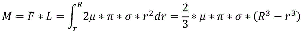
μ=3M/(2π*σ*(R3-r3))=3F*L*(R2-r2)/(2*P*(R3-r3))
wherein M is friction torque, N M; f is the detection value of the cantilever force cell, N; l is the axial movement distance of the clamp base, and is 0.0435 m; σ is the pressure per unit area of the contact surface of the upper and lower samples, and σ ═ P/π (R)2-r2),N/m2(ii) a P is an axial load value detected by a load force sensor, N; r is the outer diameter of the upper sample, m; r is the inner diameter of the upper sample, m; mu is a friction coefficient;
and 8: the surface temperatures of the upper and lower samples 12 and 37 reach the set threshold value, or the working time of the first and second driving devices 2 and 16 reaches the set threshold value, and the test of the first and second driving devices 2 and 16 is completed.
The end face friction wear test machine provided in this embodiment was tested by taking upper and lower samples having the following table properties as examples:
| material | Outer diameter (mm) | Inner diameter (mm) | Hardness of | Roughness of | ||
| | Cr12 | 30 | 22 | 52HRC | 0.4 | |
| Lower sample | Three-layer composite material | 34 | / | 86HRB | 0.4 |
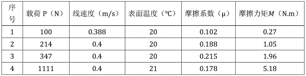
The test was carried out under dry friction conditions at an ambient temperature of 20 ℃ and an ambient humidity of 38%, and the test data obtained were as follows:
the test was carried out under oil-lubricated conditions at an ambient temperature of 14 ℃ and an ambient humidity of 38%, and the test data obtained were as follows:
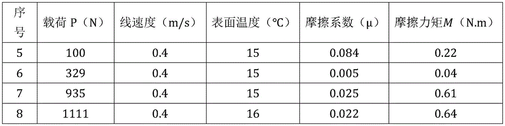
therefore, the testing machine provided by the embodiment can test the friction coefficient and the friction torque of the upper sample under different degrees of load, time, rotating speed and temperature by adopting a controlled variable method, so as to investigate the change of the friction and wear performance of the sample under different factors, and has a wider testing range compared with the prior art.
In the embodiment, three load control modes of automatic loading, semi-automatic loading and manual loading can be adopted, stepless speed regulation is realized through a variable frequency motor, test parameters such as load, rotating speed, test temperature, friction torque, friction coefficient and the like are collected and processed in real time through a computer and test data processing special software, and a statistical test result is given (or printed) in a data chart form. The testing machine can be additionally provided with a lubricating oil preheating device (not shown in the figure), and lubricating oil can be heated to a set temperature according to the test requirement and is supplied to the test cavity. In actual use, the end face friction tester can adjust and select parameters such as load, rotating speed, time, temperature, friction pair mating material, smoothness, hardness and the like in a wide range, investigate the change of the friction and wear performance of the test material under the action of various influencing factors, and evaluate the tribological characteristics and the comprehensive use performance of the test material under the dry friction or oil lubrication condition according to the change of the test parameters and the wear condition of the surface of the test sample under different conditions.
Although the present description is described in terms of embodiments, not every embodiment includes only a single embodiment, and such description is for clarity only, and those skilled in the art should be able to integrate the description as a whole, and the embodiments can be appropriately combined to form other embodiments as will be understood by those skilled in the art.
In the description of the present invention, it is noted that relational terms such as first and second, and the like, may be used solely to distinguish one entity or action from another entity or action without necessarily requiring or implying any actual such relationship or order between such entities or actions. Also, the terms "comprises," "comprising," or any other variation thereof, are intended to cover a non-exclusive inclusion, such that a process, method, article, or apparatus that comprises a list of elements does not include only those elements but may include other elements not expressly listed or inherent to such process, method, article, or apparatus. Without further limitation, an element defined by the phrase "comprising an … …" does not exclude the presence of other identical elements in a process, method, article, or apparatus that comprises the element.
In the description of the present invention, it should be further noted that the terms "upper", "lower", "inner", "outer", and the like indicate the position or positional relationship based on the position or positional relationship shown in the drawings, or the position or positional relationship which is usually placed when the products of the present invention are used, and are only for convenience of description and simplification of the description, but do not indicate or imply that the device or element referred to must have a specific orientation, be constructed and operated in a specific orientation, and thus, should not be construed as limiting the present invention.
In the description of the present invention, it should also be noted that, unless otherwise explicitly specified or limited, the terms "disposed" and "connected" are to be interpreted broadly, and may be, for example, fixedly connected, detachably connected, or integrally connected; can be mechanically or electrically connected; they may be connected directly or indirectly through intervening media, or they may be interconnected between two elements. The specific meaning of the above terms in the present invention can be understood in specific cases to those skilled in the art.
Therefore, the above description is only a preferred embodiment of the present application, and is not intended to limit the scope of the present application; all changes which come within the meaning and range of equivalency of the claims are to be embraced within their scope.
Claims (8)
1. An end face friction wear testing machine comprises a rack assembly, a testing assembly and a load loading assembly; the test assembly comprises a first driving device (2), a main shaft (8) and a clamp base (35); it is characterized in that the preparation method is characterized in that,
the first driving device (2) is fixed on the rack assembly and is in transmission connection with the spindle (8), the spindle (8) is rotationally fixed on the rack assembly around the axis of the spindle, an upper test sample (12) is fixed at the bottom of the spindle (8), a lower test sample (37) is fixed inside the upper end of the clamp base (35), and the upper test sample (12) rotates relative to the lower test sample (37) to form a friction pair; the outer side surface of the clamp base (35) is connected with one end of a fixed steel wire rope (38), the other end of the steel wire rope (38) is connected with a cantilever force transducer (39) fixed on the rack assembly, and the cantilever force transducer (39) is connected with a computer;
the load loading assembly comprises a second driving device (16), a lifting device (17) and a loading shaft (27);
the second driving device (16) and the lifting device (17) are fixed on the frame assembly, the second driving device (16) is in transmission connection with the lifting device (17), a spring loading device and a load force sensor (24) are connected between the lifting end of the lifting device (17) and the bottom end of the loading shaft (27), and the load force sensor (24) is connected with the computer; the loading shaft (27) is coaxial with the main shaft (8), and the top end of the loading shaft is pressed against the bottom end of the clamp base (35) through a bearing unit.
2. The end face friction wear testing machine is characterized in that the spring loading device comprises a spring lower pressing plate (19), a spring upper pressing plate (22), a loading contact (25) and a loading cushion block (26) which are coaxially arranged from bottom to top in sequence, wherein the upper end of the loading contact (25) is pressed against the loading cushion block (26) into an inner hole at the bottom end of the loading shaft (27); the upper end of the load force sensor (24) is fixedly connected with the loading contact (25), the bottom end of the load force sensor is fixed on the sensor fixing block (23), and the sensor fixing block (23) is fixed on the spring upper pressure plate (22).
3. An end face friction wear testing machine according to claim 2, characterized in that the face of the loading contact (25) pressing against the loading pad (26) is a cambered surface.
4. The end face friction wear testing machine according to claim 2, characterized in that the spring comprises a first spring (21) and a second spring (20) which are sleeved in and out, wherein the inner diameter of the second spring (20) is larger than the outer diameter of the first spring (21).
5. The end face friction wear testing machine according to claim 1, characterized in that the bearing unit comprises a loading bearing sleeve (33), a thrust knuckle bearing (34), a second deep groove ball bearing (32) and a thrust ball bearing (31) are coaxially connected between an inner hole of the loading bearing sleeve (33) and the upper end of a loading shaft (27) from top to bottom in sequence, and the upper end of the thrust knuckle bearing (34) is pressed against the bottom of the clamp base (35).
6. The end face friction wear testing machine according to claim 5, characterized in that a loading guide sleeve (28) is sleeved outside the loading shaft (27) and fixed on the frame assembly through the loading guide sleeve (28), and a loading bush (29) and a felt (30) are coaxially connected between the outer wall of the loading shaft (27) and the inner hole of the loading guide sleeve (28).
7. An end face friction wear testing machine according to claim 1, characterized in that the main shaft (8) is fixed on the frame component through the main shaft box, a first deep groove ball bearing (9) is coaxially connected between the upper side of the outer wall of the main shaft (8) and the inner hole of the main shaft box, and a tapered roller bearing (10) and a cylindrical roller bearing (11) are coaxially connected between the lower side of the outer wall of the main shaft (8) and the inner hole of the main shaft box.
8. The end face friction wear testing machine according to claim 1, characterized in that the bottom outer wall and the bottom end face of the main shaft (8) are respectively provided with a radial pin and an axial pin for fixing the upper test sample (12).
Priority Applications (1)
| Application Number | Priority Date | Filing Date | Title |
|---|---|---|---|
| CN202022069675.5U CN212646373U (en) | 2020-09-18 | 2020-09-18 | End surface friction and wear testing machine |
Applications Claiming Priority (1)
| Application Number | Priority Date | Filing Date | Title |
|---|---|---|---|
| CN202022069675.5U CN212646373U (en) | 2020-09-18 | 2020-09-18 | End surface friction and wear testing machine |
Publications (1)
| Publication Number | Publication Date |
|---|---|
| CN212646373U true CN212646373U (en) | 2021-03-02 |
Family
ID=74762926
Family Applications (1)
| Application Number | Title | Priority Date | Filing Date |
|---|---|---|---|
| CN202022069675.5U Active CN212646373U (en) | 2020-09-18 | 2020-09-18 | End surface friction and wear testing machine |
Country Status (1)
| Country | Link |
|---|---|
| CN (1) | CN212646373U (en) |
Cited By (1)
| Publication number | Priority date | Publication date | Assignee | Title |
|---|---|---|---|---|
| CN113267417A (en) * | 2021-06-03 | 2021-08-17 | 上海应用技术大学 | Coating friction wear detection testing machine |
-
2020
- 2020-09-18 CN CN202022069675.5U patent/CN212646373U/en active Active
Cited By (1)
| Publication number | Priority date | Publication date | Assignee | Title |
|---|---|---|---|---|
| CN113267417A (en) * | 2021-06-03 | 2021-08-17 | 上海应用技术大学 | Coating friction wear detection testing machine |
Similar Documents
| Publication | Publication Date | Title |
|---|---|---|
| CN112067487A (en) | End face friction and wear testing machine and testing method thereof | |
| CN102053015A (en) | Tester for thrust bearing | |
| CN110954427B (en) | A multifunctional miniature precision bearing experimental platform | |
| CN101339113A (en) | Machine Tool Spindle Journal Bearing Pad Tribological Performance Testing Machine | |
| CN212646373U (en) | End surface friction and wear testing machine | |
| CN111504831B (en) | Bearing steel ball friction and wear performance test bench and test method | |
| CN109341509B (en) | A measuring device and testing method for rolling bearing lubricating film thickness | |
| KR20170004770A (en) | Vertical torque measurement apparatus for bearing | |
| JP2016161405A (en) | Inspection apparatus and inspection method of rolling bearing | |
| CN104748692A (en) | Three-roller integrated load roller pin optic elastohydrodynamic tester | |
| CN105122027A (en) | Inspection device | |
| CN105651513A (en) | Testing system for lubrication characteristic of vertical water-lubricated tilting thrust bearing liquid film | |
| CN116413030B (en) | A friction and wear testing system for surface damage of rolling ball bearings | |
| CN218383050U (en) | Tin oxide electrode resistance detection device | |
| CN108507895A (en) | A kind of vertical type multifunctional friction-wear test test machine | |
| CN110927055A (en) | Device and method for measuring friction coefficient between inner ring and outer ring of bearing | |
| CN219474960U (en) | Bearing ball and raceway friction and wear test system for rolling ball bearings | |
| CN210221495U (en) | Bearing life testing device | |
| CN217132563U (en) | Bearing testing device | |
| CN219474962U (en) | A loading system for friction and wear testing of rolling ball bearing materials | |
| CN205449498U (en) | Be used for lubricated tilting pad thrust bearing liquid film lubrication characteristic test system of vertical water | |
| CN210014915U (en) | Test device for detecting service life of bearing | |
| CN114526914B (en) | Load cell unloading device, fretting wear testing machine and testing method | |
| CN110345832B (en) | High-precision end jump detection device | |
| CN119574163A (en) | B-axis powered tool holder simulation loading test bench |
Legal Events
| Date | Code | Title | Description |
|---|---|---|---|
| GR01 | Patent grant | ||
| GR01 | Patent grant | ||
| TR01 | Transfer of patent right |
Effective date of registration: 20240926 Address after: No.16, Yulan Avenue, Baiyan Science Park, high tech Zone, Hefei City, Anhui Province, 230088 Patentee after: HEFEI BOLIN ADVANCED MATERIALS Co.,Ltd. Country or region after: China Address before: 230000 No.14 Yulan Avenue, Taohua Town, Feixi County, Hefei City, Anhui Province Patentee before: HEFEI DINGJU PRECISION MANUFACTURING CO.,LTD. Country or region before: China |
|
| TR01 | Transfer of patent right |