CN2124828U - Self-air charging system for bicycle - Google Patents
Self-air charging system for bicycle Download PDFInfo
- Publication number
- CN2124828U CN2124828U CN92209133U CN92209133U CN2124828U CN 2124828 U CN2124828 U CN 2124828U CN 92209133 U CN92209133 U CN 92209133U CN 92209133 U CN92209133 U CN 92209133U CN 2124828 U CN2124828 U CN 2124828U
- Authority
- CN
- China
- Prior art keywords
- bicycle
- screw rod
- wheel
- shell
- eccentric wheel
- Prior art date
- Legal status (The legal status is an assumption and is not a legal conclusion. Google has not performed a legal analysis and makes no representation as to the accuracy of the status listed.)
- Granted
Links
Images

Classifications
-
- B—PERFORMING OPERATIONS; TRANSPORTING
- B60—VEHICLES IN GENERAL
- B60C—VEHICLE TYRES; TYRE INFLATION; TYRE CHANGING; CONNECTING VALVES TO INFLATABLE ELASTIC BODIES IN GENERAL; DEVICES OR ARRANGEMENTS RELATED TO TYRES
- B60C23/00—Devices for measuring, signalling, controlling, or distributing tyre pressure or temperature, specially adapted for mounting on vehicles; Arrangement of tyre inflating devices on vehicles, e.g. of pumps or of tanks; Tyre cooling arrangements
- B60C23/10—Arrangement of tyre-inflating pumps mounted on vehicles
- B60C23/12—Arrangement of tyre-inflating pumps mounted on vehicles operated by a running wheel
- B60C23/137—Arrangement of tyre-inflating pumps mounted on vehicles operated by a running wheel comprising cam driven pistons
Landscapes
- Engineering & Computer Science (AREA)
- Mechanical Engineering (AREA)
- Compressors, Vaccum Pumps And Other Relevant Systems (AREA)
Abstract
The utility model relates to a self-air charging system for a bicycle, a miniature inflator is installed on the spoke of a bicycle wheel directly, an eccentric wheel is fixed on a bicycle shaft to make use of the rotation of the bicycle wheel to drive the eccentric wheel to rotate, an inflator piston is driven to move up and down by a screw rod, and the inflation process is completed automatically. The system can inflate for a bicycle tyre at any time, a user can ride the bicycle to inflate the bicycle tyre simultaneously, and the utility model has convenient use.
Description
The utility model is a kind of device of giving the tire self-inflating of bicycle or other Light-duty Vehicle.
The inflation of tire of existing bicycle or motor bike generally depends on extraneous pressurized air, as: electric air pump or manual pump are given inflation of tire, this inflation mode is that source of the gas separates with bike tyre, when finding the tyre pressure deficiency, can not find for the moment source of the gas again, this can compatriots make troubles or worries to riding.
The purpose of this utility model is that providing a kind of at above-mentioned weak point is directly installed on mini inflatable device on bicycle front-wheel or the trailing wheel, gas filled device and bicycle are combined into one, utilize the power of the rotation of wheel, give Tyre inflating at any time as micro pump.
This device has overcome extraneous worry of inflating mode, especially when finding that tire slightly leaks gas, needn't worry also that this device can be given inflation of tire while riding, keep normally and ride.
The structure of this device is this realization: it has a micro pump that is fixed on the bicycle rung bar, it is connected as a single entity piston rod in the micro pump with the eccentric wheel that is fixed on bicycle front-wheel or trailing wheel, eccentric wheel is installed in the rotation that utilizes wheel in the bicycle shaft, and eccentric wheel moves up and down piston and finishes gas replenishment process in micro pump.
Description of drawings:
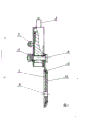
Fig. 1 is bicycle inflator's (facing structural representation);
Fig. 2 is this device side TV structure scheme drawing.
Below in conjunction with accompanying drawing, this device specifically is illustrated.
Bicycle self-inflating device of the present utility model has a micro pump, this inflator shell (2) is an ellipse cylinder, in the upper end of inflator shell (2) safety pressure-limiting valve (1) is arranged, there is an air vent screw its inside, with a ball that seals is arranged under the limit spring, ball is backed down overvoltage gas is spilt from screw hole when the pressure in the cylinder surpasses certain value, reaches the pressure limiting purpose.Have one screw rod (9) is installed at inflator shell-side face, also there is mounting hole (17) lower end, it is installed in inflator on the vehicle wheel spoke of bicycle front-wheel or trailing wheel by supporting plate (meaning not shown in the figures) bolt and nut, also there is simultaneously one to give vent to anger and chew (13) in the upper end of inflator shell (2), one end of breather pipe (14) is connected in to give vent to anger by nut and chews on (13), the other end is connected on the valve inside of cycle wheel tire, because nut place, breather pipe (14) two ends all has rubber mount (16) to play sealing function, the central portion place has a chute at inflator shell (2), and it guarantees that screw rod (6) moves up and down.
Having its shape of a piston (4) and inflator shell (2) ellipse to match in the inflator shell (2), is a solid.In the groove of piston (4) top, O type sealing rubber ring (3) is housed to be had simultaneously and prevents that dust from entering the wool felt (5) in the cylinder, O type sealing rubber ring (3) is also being controlled the interior air hole of piston body (4), center, lower end at piston (4) studs with a sleeve, connecting rod (6) passes in sleeve, accompanying spring by nut (10) is fixed on the micro pump shell (2), the right-hand member (shown in Figure 2) of chute in screw rod (6) by inflator shell (2) connects eccentric wheel (15), at connecting rod (6) packing ring spring and nut are housed, guarantee that screw rod (6) can move by easy on and off in the chute of inflator shell (2).
The structure of eccentric wheel (15) is such: a base plate (11) and gland (12) are respectively arranged about eccentric wheel (15), one circle ball is arranged in the middle of its base plate and the eccentric wheel, eccentric wheel can freely be rotated, and base plate (11) and gland (12) are installed in (not shown) on the axle for bicycle by eccentric orfice (8).
Micro pump is made by engineering plastics, and eccentric wheel is made by steel plate or copper coin.
During use, because micro pump is installed on the cycle wheel, when cycle wheel rotated, urgent quilt rotated eccentric wheel (15), drove piston by screw rod (6) and moved up and down, and finished the gas replenishment process to bike tire.Show that through experiment in one week of wheel of bicycle, piston is finished gas replenishment process one time.
This bicycle inflator is installed on 26 type bicycle front-wheels or the trailing wheel, stroke can be given a tire sufficient gas for 200 meters, when tire pressure reaches certain value, because the effect of safety pressure-limiting valve (1), inflator is no longer given Tyre inflating, when inner pressure of air cylinder reduces, that is to say when tire pressure is not enough, the rotation of bicycle will be given Tyre inflating at any time, therefore the cyclist is or else not enough worried for tyre pressure, sometimes micro pump (2) can be taken out from wheel, find the air pressure deficiency at any time, load onto at any time and can give inflation of tire voluntarily.This device extremely user easy to use likes.
Claims (4)
1, a kind of bicycle self-inflating device, this device has a micro pump that is fixed on the vehicle wheel spoke, it is characterized in that: this micro pump has a miniature shell (2), one piston (4) is arranged in its shell, be connected with a screw rod (6) on this piston (4), it be fixed on eccentric wheel on the cycle wheel axle (15) and be connected as a single entity.
2, bicycle self-inflating device according to claim 1, it is characterized in that: micro pump shell (2) is ellipse, in inflator shell (2) upper end safety pressure-limiting valve (1) and outlet nozzle (13) are housed, one end nut of breather pipe (14) is connected on the valve inside of bike tyre, and all there is rubber mount (16) at nut place, breather pipe (14) two ends.
3, bicycle self-inflating device according to claim 1 is characterized in that: a circle ball is arranged between eccentric wheel (15) and the base plate (11).
4, bicycle self-inflating device according to claim 1, it is characterized in that: the right-hand member of screw rod (6) connects eccentric wheel (15), this screw rod (6) passes the sleeve of piston (4), chute by inflator shell (2), this screw rod (6) left end is equipped with packing ring, spring and nut can freely move up and down screw rod (6).
Priority Applications (1)
| Application Number | Priority Date | Filing Date | Title |
|---|---|---|---|
| CN92209133U CN2124828U (en) | 1992-05-11 | 1992-05-11 | Self-air charging system for bicycle |
Applications Claiming Priority (1)
| Application Number | Priority Date | Filing Date | Title |
|---|---|---|---|
| CN92209133U CN2124828U (en) | 1992-05-11 | 1992-05-11 | Self-air charging system for bicycle |
Publications (1)
| Publication Number | Publication Date |
|---|---|
| CN2124828U true CN2124828U (en) | 1992-12-16 |
Family
ID=4954483
Family Applications (1)
| Application Number | Title | Priority Date | Filing Date |
|---|---|---|---|
| CN92209133U Granted CN2124828U (en) | 1992-05-11 | 1992-05-11 | Self-air charging system for bicycle |
Country Status (1)
| Country | Link |
|---|---|
| CN (1) | CN2124828U (en) |
Cited By (2)
| Publication number | Priority date | Publication date | Assignee | Title |
|---|---|---|---|---|
| CN104786760A (en) * | 2015-03-11 | 2015-07-22 | 天津金轮自行车集团有限公司 | Bicycle inflation assembly |
| CN110203021A (en) * | 2019-06-13 | 2019-09-06 | 国网山东省电力公司青州市供电公司 | A kind of automobile tire intelligence inflation system and intelligent inflation method |
-
1992
- 1992-05-11 CN CN92209133U patent/CN2124828U/en active Granted
Cited By (2)
| Publication number | Priority date | Publication date | Assignee | Title |
|---|---|---|---|---|
| CN104786760A (en) * | 2015-03-11 | 2015-07-22 | 天津金轮自行车集团有限公司 | Bicycle inflation assembly |
| CN110203021A (en) * | 2019-06-13 | 2019-09-06 | 国网山东省电力公司青州市供电公司 | A kind of automobile tire intelligence inflation system and intelligent inflation method |
Similar Documents
| Publication | Publication Date | Title |
|---|---|---|
| CN2124828U (en) | Self-air charging system for bicycle | |
| CN2150088Y (en) | Full-enclosed automatic inflating pump | |
| CN2163250Y (en) | Pedle air storage inflator | |
| CN2183920Y (en) | Novel charging connector | |
| CN2230250Y (en) | Tire-inflating press needle | |
| CN87201520U (en) | Device for inflating vehicle tyre automatically | |
| CN2263719Y (en) | Bicycle attached pump | |
| CN2180503Y (en) | Self-inflation apparatus for bicycle | |
| CN2306894Y (en) | Inner tube having separate inflatable chamber | |
| CN2154191Y (en) | Inflater with bicycle | |
| CN2181420Y (en) | Automatic inflating pump for bicycle | |
| CN2136759Y (en) | Tyre inflating valve cap cover for motor-driven vehicle | |
| CN2263209Y (en) | Pedal air pump | |
| CN2168965Y (en) | Automatic pump for bicycle and motorcycle | |
| CN2194282Y (en) | Saddle type inflator for bicycle | |
| CN2146385Y (en) | High-pressure automatic tyre-inflating pump for bicycles | |
| CN2064317U (en) | Automatic tyre inflating device in tyre | |
| CN85202403U (en) | Automatic air charging system for travelling tyre | |
| CN2409072Y (en) | Automatic inflating valve inside | |
| CN2467344Y (en) | Automatic-filling gas apparatus | |
| CN2135526Y (en) | Force aid device for bicycle | |
| CN2180504Y (en) | Miniature automatic inflation pump for bicycle | |
| CN2249716Y (en) | Bicycle with air pump | |
| CN2074718U (en) | Automatic inflation tyre | |
| CN87200021U (en) | Universal bicycle automatic inflator |
Legal Events
| Date | Code | Title | Description |
|---|---|---|---|
| C06 | Publication | ||
| PB01 | Publication | ||
| C14 | Grant of patent or utility model | ||
| GR01 | Patent grant | ||
| C57 | Notification of unclear or unknown address | ||
| DD01 | Delivery of document by public notice |
Addressee: Zhang Baoxing Document name: Notice of termination |
|
| C19 | Lapse of patent right due to non-payment of the annual fee | ||
| CF01 | Termination of patent right due to non-payment of annual fee |