CN212033521U - Mutual inductance sleeve and switch cabinet - Google Patents
Mutual inductance sleeve and switch cabinet Download PDFInfo
- Publication number
- CN212033521U CN212033521U CN202021061685.8U CN202021061685U CN212033521U CN 212033521 U CN212033521 U CN 212033521U CN 202021061685 U CN202021061685 U CN 202021061685U CN 212033521 U CN212033521 U CN 212033521U
- Authority
- CN
- China
- Prior art keywords
- mutual inductance
- bushing
- insulating sleeve
- installation
- electrical
- Prior art date
- Legal status (The legal status is an assumption and is not a legal conclusion. Google has not performed a legal analysis and makes no representation as to the accuracy of the status listed.)
- Expired - Fee Related
Links
Images


Landscapes
- Patch Boards (AREA)
Abstract
本实用新型公开了一种互感套管及开关柜,互感套管包括:电连接体、绝缘套体以及互感器。其中,电连接体连接于至少两个待连接端之间;绝缘套体,套装在所述电连接体外侧;互感器具有安装孔,所述安装孔限位安装在所述绝缘套体的外周面上。通过绝缘套体套接在绝缘端子的外周壁面上,实现对电连接体的进一步绝缘,此外,通过互感器直接与绝缘套体的限位安装,实现互感器安装的稳定性的同时,大大提高了安装的便利性。同时保证互感套管同时具有穿墙搭接、保护、测量的功能,此外,在互感套管与断路器配合安装时实现互感器和断路器一体化,使断路器自带保护和测量的功能,从而间接减小了开关柜体积和设计装配难度,降低了成本。
The utility model discloses a mutual inductance bushing and a switch cabinet. The mutual inductance bushing comprises an electrical connection body, an insulating sleeve body and a mutual inductor. The electrical connecting body is connected between at least two terminals to be connected; the insulating sleeve is sleeved on the outside of the electrical connecting body; face. The insulating sleeve is sleeved on the outer peripheral wall of the insulating terminal to further insulate the electrical connection body. In addition, through the limit installation of the transformer directly with the insulating sleeve, the stability of the installation of the transformer is greatly improved. ease of installation. At the same time, it is ensured that the mutual inductance bushing has the functions of lap, protection and measurement through the wall at the same time. In addition, when the mutual inductance bushing and the circuit breaker are installed together, the integration of the mutual inductor and the circuit breaker is realized, so that the circuit breaker has its own protection and measurement functions. Therefore, the volume of the switch cabinet and the difficulty of design and assembly are indirectly reduced, and the cost is reduced.
Description
技术领域technical field
本实用新型涉及输配电技术领域,具体涉及一种互感套管及开关柜。The utility model relates to the technical field of power transmission and distribution, in particular to a mutual inductance bushing and a switch cabinet.
背景技术Background technique
开关柜作为一种电设备,外线先进入柜内主控开关,然后进入分控开关,各分路按其需要设置。如仪表、自控、电动机磁力开关,各种交流接触器等,有的还设高压室与低压室开关柜,设有高压母线,如发电厂等,有的还设有为保主要设备的低周减载。随着技术要求的不断更新,开关柜要求集保护和测量功能为一体。As a kind of electrical equipment, the switch cabinet first enters the main control switch in the cabinet, and then enters the sub-control switch, and each sub-circuit is set according to its needs. Such as instruments, automatic control, motor magnetic switches, various AC contactors, etc., and some also have high-voltage room and low-voltage room switch cabinets, high-voltage busbars, such as power plants, etc. load shedding. With the continuous updating of technical requirements, switchgear requires protection and measurement functions as a whole.
中国专利文献CN210040949U,公开了一种高压开关柜,包括隔板、隔离开关、带屏蔽穿墙套管、断路器开关、穿心式电流互感器及接地刀闸;其中,带屏蔽穿墙套管包括:中心导体、互感器、绝缘子和安装凸台,使用时,将安装凸台与互感器连接,并在凸台两侧的中心导体外套设绝缘子以实现安装作用。Chinese patent document CN210040949U discloses a high-voltage switchgear, which includes a partition, an isolation switch, a shielded wall bushing, a circuit breaker switch, a through-core current transformer and a grounding switch; wherein the shielded wall bushing Including: center conductor, transformer, insulator and installation boss, when in use, connect the installation boss with the transformer, and set insulators on the center conductor on both sides of the boss to achieve installation.
但是,上述结构的开关柜,由于需要单独安装适配于互感器的安装凸台,且需要单独设置安装凸台安装位置,并截断绝缘子,将安装凸台安装在被截断的两个绝缘子之间,导致实际带屏蔽穿墙套管安装使用较为复杂,造成使用上的不便。However, in the switchgear with the above structure, the installation bosses adapted to the transformers need to be installed separately, and the installation positions of the installation bosses need to be separately set, the insulators are cut off, and the installation bosses are installed between the two cut off insulators. , resulting in more complicated installation and use of the actual shielded wall bushing, resulting in inconvenience in use.
实用新型内容Utility model content
因此,本实用新型所要解决的技术问题在于现有技术中的由于需要单独安装适配于互感器的安装凸台,且需要单独设置安装凸台安装位置后,并截断绝缘子,将安装凸台安装在被截断的两个绝缘子之间,导致实际带屏蔽穿墙套管安装使用较为复杂,造成使用上的不便的缺陷。Therefore, the technical problem to be solved by the present invention is that in the prior art, since the installation bosses adapted to the transformers need to be installed separately, and the installation positions of the installation bosses need to be set separately, the insulators are cut off and the installation bosses are installed. Between the two cut off insulators, the actual installation and use of the shielded wall bushing is complicated, resulting in inconvenience in use.
为此,本实用新型提供一种互感套管,包括:To this end, the utility model provides a mutual inductance bushing, comprising:
电连接体,连接于至少两个待连接端之间;an electrical connector, connected between at least two to-be-connected ends;
绝缘套体,套装在所述电连接体外侧;an insulating sleeve, sleeved on the outside of the electrical connector;
互感器,具有安装孔,所述安装孔限位安装在所述绝缘套体的外周面上。The transformer has a mounting hole, and the mounting hole is limitedly mounted on the outer peripheral surface of the insulating sleeve body.
可选地,上述的互感套管,所述绝缘套体为伞裙。Optionally, in the above-mentioned mutual inductance sleeve, the insulating sleeve body is an umbrella skirt.
可选地,上述的互感套管,所述绝缘套体与所述安装孔过盈配合。Optionally, in the above-mentioned mutual inductance sleeve, the insulating sleeve body and the installation hole are in an interference fit.
可选地,上述的互感套管,所述电连接体包括中心导体和安装套体,所述安装套体套接在所述中心导体外侧;Optionally, in the above-mentioned mutual inductance bushing, the electrical connection body includes a central conductor and an installation sleeve, and the installation sleeve is sleeved on the outside of the central conductor;
所述绝缘套体安装在所述安装套体外侧。The insulating sleeve body is installed outside the installation sleeve body.
可选地,上述的互感套管,所述互感器为穿心式电流互感器。Optionally, in the above-mentioned mutual inductor bushing, the transformer is a through-core current transformer.
一种开关柜,包括A switchgear, comprising
隔板,分隔至少两个待连接室体,任一所述待连接室体具有至少一个所述待连接端;a separator, separating at least two chamber bodies to be connected, any of the chamber bodies to be connected has at least one end to be connected;
以及上述的互感套管,所述互感套管穿设在所述隔板的两侧,所述电连接体与相邻的至少两个所述待连接端连通。And the above-mentioned mutual inductance sleeve, the mutual inductance sleeve is penetrated on both sides of the partition plate, and the electrical connection body is communicated with at least two adjacent to-be-connected ends.
可选地,上述的开关柜,所述电连接体具有两个连接端,Optionally, in the above switch cabinet, the electrical connector has two connection ends,
所述开关柜还包括设置在两个待连接室体内的连接电缆和断路器;The switch cabinet also includes connecting cables and circuit breakers arranged in the two chambers to be connected;
所述电连接体的至少一端连接隔离开关和电缆;所述电连接体的至少一端连接真空断路器。At least one end of the electrical connecting body is connected to the isolation switch and the cable; at least one end of the electrical connecting body is connected to the vacuum circuit breaker.
可选地,上述的开关柜,还包括安装结构,所述安装结构包括:连接件和锁定件;Optionally, the above-mentioned switch cabinet further includes an installation structure, and the installation structure includes: a connecting piece and a locking piece;
所述连接件卡装在所述电连接体外侧,所述锁定件穿设在所述连接件的连接孔内,且所述锁定件所述隔板锁定连接。The connecting piece is clamped on the outside of the electrical connecting body, the locking piece is penetrated in the connecting hole of the connecting piece, and the locking piece is locked and connected to the partition.
可选地,上述的开关柜,所述连接件为至少两个拼接连接体,所述拼接连接体具有呈弧面的凹槽;Optionally, in the above-mentioned switch cabinet, the connector is at least two splicing connectors, and the splicing connectors have an arc-shaped groove;
所有所述拼接连接体的凹槽拼接为所述连接件的限位孔,所述电连接体卡装在所述限位孔内。All the grooves of the spliced connectors are spliced into limit holes of the connector, and the electrical connectors are clamped in the limit holes.
可选地,上述的开关柜,具有两个所述拼接连接体,所述凹槽呈半圆形。Optionally, the above-mentioned switch cabinet has two of the splicing connectors, and the groove is semicircular.
本实用新型提供的技术方案,具有如下优点:The technical scheme provided by the utility model has the following advantages:
1.本实用新型提供的互感套管,包括:电连接体、绝缘套体以及互感器。其中,电连接体连接于至少两个待连接端之间;绝缘套体,套装在所述电连接体外侧;互感器具有安装孔,所述安装孔限位安装在所述绝缘套体的外周面上。1. The mutual inductance bushing provided by the present utility model includes: an electrical connection body, an insulating sleeve body and a mutual inductor. The electrical connecting body is connected between at least two terminals to be connected; the insulating sleeve is sleeved on the outside of the electrical connecting body; face.
此结构的互感套管,通过绝缘套体套接在绝缘端子的外周壁面上,实现对电连接体的进一步绝缘,此外,通过互感器直接与绝缘套体的限位安装,实现互感器安装的稳定性的同时,大大提高了安装的便利性。同时保证互感套管同时具有穿墙搭接、保护、测量的功能,此外,在互感套管与断路器配合安装时实现互感器和断路器一体化,使断路器自带保护和测量的功能,从而间接减小了开关柜体积和设计装配难度,降低了成本。The mutual inductance bushing of this structure is sleeved on the outer peripheral wall surface of the insulating terminal through the insulating sleeve to realize further insulation of the electrical connection body. At the same time of stability, the convenience of installation is greatly improved. At the same time, it is ensured that the mutual inductance bushing has the functions of lap, protection and measurement through the wall at the same time. In addition, when the mutual inductance bushing and the circuit breaker are installed together, the integration of the mutual inductor and the circuit breaker is realized, so that the circuit breaker has its own protection and measurement functions. Thus, the volume of the switch cabinet and the difficulty of design and assembly are indirectly reduced, and the cost is reduced.
2.本实用新型提供的互感套管,所述绝缘套体为伞裙。所述绝缘套体与所述安装孔过盈配合。此结构的互感套管,由于绝缘套体可以采用柔性材质的伞裙,从而绝缘套体与安装孔之间的连接关系为过盈配合,进一步方便互感器与绝缘套体的安装以及使用。此外,伞裙的设置,增加互感套管表面爬电距离,防止污闪。2. In the mutual inductance sleeve provided by the present invention, the insulating sleeve body is an umbrella skirt. The insulating sleeve body is in interference fit with the mounting hole. In the mutual inductance sleeve of this structure, since the insulating sleeve body can be made of a flexible material shed, the connection between the insulating sleeve body and the installation hole is an interference fit, which further facilitates the installation and use of the transformer and the insulating sleeve body. In addition, the setting of the umbrella skirt increases the creepage distance on the surface of the mutual inductance casing to prevent pollution flashover.
3.本实用新型提供的开关柜,包括:隔板以及互感套管。其中,隔板分隔至少两个待连接室体,任一所述待连接室体具有至少一个所述待连接端;所述互感套管穿设在所述隔板的两侧,所述电连接体与相邻的至少两个所述待连接端连通。互感套管安装在隔板的两侧,从而与两侧的连接端分IE连接,进一步保证断路器连接的可靠性,在互感套管与断路器配合安装时实现互感器和断路器一体化,使断路器自带保护和测量的功能,从而间接减小了开关柜体积和设计装配难度,降低了成本。3. The switch cabinet provided by the utility model includes: a partition plate and a mutual inductance bushing. Wherein, the partition plate separates at least two chamber bodies to be connected, and any of the chamber bodies to be connected has at least one end to be connected; The body communicates with at least two adjacent ends to be connected. The mutual inductance bushing is installed on both sides of the partition, so as to be connected with the connection ends on both sides by IE, which further ensures the reliability of the circuit breaker connection. The circuit breaker has its own protection and measurement functions, thereby indirectly reducing the volume of the switch cabinet, the difficulty of design and assembly, and the cost.
附图说明Description of drawings
为了更清楚地说明本实用新型具体实施方式或现有技术中的技术方案,下面将对具体实施方式或现有技术描述中所需要使用的附图作简单地介绍,显而易见地,下面描述中的附图是本实用新型的一些实施方式,对于本领域普通技术人员来讲,在不付出创造性劳动的前提下,还可以根据这些附图获得其他的附图。In order to more clearly illustrate the specific embodiments of the present invention or the technical solutions in the prior art, the following will briefly introduce the accompanying drawings that need to be used in the description of the specific embodiments or the prior art. Obviously, the following descriptions The accompanying drawings are some embodiments of the present invention. For those of ordinary skill in the art, other drawings can also be obtained based on these drawings without creative efforts.
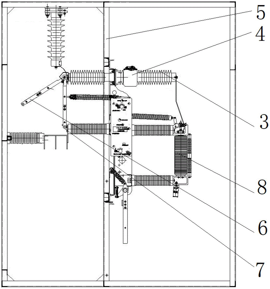
图1为实施例1中所提供的开关柜的结构示意图;1 is a schematic structural diagram of a switch cabinet provided in
图2为实施例1中所提供的互感套管的结构示意图;2 is a schematic structural diagram of the mutual inductance bushing provided in
附图标记说明:Description of reference numbers:
1-中心导体;2-安装套体;1-Center conductor; 2-Installation sleeve;
3-绝缘套体;4-互感器;5-隔板;6-隔离开关;7-电缆;8-真空断路器;3-insulating casing; 4-transformer; 5-partition; 6-isolating switch; 7-cable; 8-vacuum circuit breaker;
具体实施方式Detailed ways
下面将结合附图对本实用新型的技术方案进行清楚、完整地描述,显然,所描述的实施例是本实用新型一部分实施例,而不是全部的实施例。基于本实用新型中的实施例,本领域普通技术人员在没有做出创造性劳动前提下所获得的所有其他实施例,都属于本实用新型保护的范围。The technical solutions of the present invention will be clearly and completely described below with reference to the accompanying drawings. Obviously, the described embodiments are a part of the embodiments of the present invention, not all of the embodiments. Based on the embodiments of the present invention, all other embodiments obtained by those of ordinary skill in the art without creative work fall within the protection scope of the present invention.
在本实用新型的描述中,需要说明的是,术语“中心”、“上”、“下”、“左”、“右”、“竖直”、“水平”、“内”、“外”等指示的方位或位置关系为基于附图所示的方位或位置关系,仅是为了便于描述本实用新型和简化描述,而不是指示或暗示所指的装置或元件必须具有特定的方位、以特定的方位构造和操作,因此不能理解为对本实用新型的限制。此外,术语“第一”、“第二”、“第三”仅用于描述目的,而不能理解为指示或暗示相对重要性。In the description of the present invention, it should be noted that the terms "center", "upper", "lower", "left", "right", "vertical", "horizontal", "inner" and "outer" The orientation or positional relationship indicated by etc. is based on the orientation or positional relationship shown in the accompanying drawings, which is only for the convenience of describing the present invention and simplifying the description, rather than indicating or implying that the referred device or element must have a specific orientation, with a specific orientation. Therefore, it should not be construed as a limitation on the present invention. Furthermore, the terms "first", "second", and "third" are used for descriptive purposes only and should not be construed to indicate or imply relative importance.
在本实用新型的描述中,需要说明的是,除非另有明确的规定和限定,术语“安装”、“相连”、“连接”应做广义理解,例如,可以是固定连接,也可以是可拆卸连接,或一体地连接;可以是机械连接,也可以是电连接;可以是直接相连,也可以通过中间媒介间接相连,可以是两个元件内部的连通。对于本领域的普通技术人员而言,可以具体情况理解上述术语在本实用新型中的具体含义。In the description of the present invention, it should be noted that, unless otherwise expressly specified and limited, the terms "installed", "connected" and "connected" should be understood in a broad sense, for example, it may be a fixed connection or a connectable connection. Detachable connection, or integral connection; may be mechanical connection or electrical connection; may be direct connection, or indirect connection through an intermediate medium, or internal communication between two components. For those of ordinary skill in the art, the specific meanings of the above terms in the present invention can be understood in specific situations.
此外,下面所描述的本实用新型不同实施方式中所涉及的技术特征只要彼此之间未构成冲突就可以相互结合。In addition, the technical features involved in the different embodiments of the present invention described below can be combined with each other as long as there is no conflict with each other.
实施例1Example 1
本实施例提供一种开关柜,如图1和图2所示,包括:隔离开关6和电缆7、真空断路器8、隔板5以及互感套管。其中,隔板5分隔两个待连接室体,任一待连接室体具有一个待连接端;互感套管穿设在隔板5的两侧,互感套管的一端连接隔离开关6和电缆7,另一端连接真空断路器8后连接变压器。This embodiment provides a switch cabinet, as shown in FIG. 1 and FIG. 2 , including: a disconnecting
如图2所示,本实施例提供的互感套管,包括:电连接体、绝缘套体3以及互感器4。其中,电连接体包括中心导体1和安装套体2,中心导体1的两端分别连接在两个待连接端,安装套体2套接在中心导体1外侧;绝缘套体3安装在安装套体2外侧;互感器4,具有安装孔,安装孔限位安装在绝缘套体3的外周面上。例如,互感器4为穿心式电流互感器4。本实施例中,中心导体1采用T2铜或同性能导电材料。安装套体2为复合绝缘材料,例如可以为复合绝缘材料环氧树脂,当然在其他可选的实施方式中,复合绝缘材料也可以选用高压硅橡胶。安装套体2浇筑或包覆在中心导体1的外侧。As shown in FIG. 2 , the mutual inductance bushing provided in this embodiment includes: an electrical connection body, an insulating
具体而言,绝缘套体3为伞裙。且绝缘套体3与安装孔过盈配合。伞裙的材质可以为硅胶材质,由于绝缘套体3可以采用柔性材质的伞裙,从而绝缘套体3与安装孔之间的连接关系为过盈配合,进一步方便互感器4与绝缘套体3的安装以及使用。此外,伞裙的设置,增加互感套管表面爬电距离,防止污闪。Specifically, the insulating
上述的还包括安装结构,安装结构包括:连接件和锁定件;连接件卡装在电连接体外侧,锁定件穿设在连接件的连接孔内,且锁定件隔板5锁定连接。连接件为至少两个拼接连接体,拼接连接体具有呈弧面的凹槽;所有拼接连接体的凹槽拼接为连接件的限位孔,电连接体卡装在限位孔内。具体而言,连接件具有两个拼接连接体,凹槽呈半圆形。The above also includes an installation structure, the installation structure includes: a connecting piece and a locking piece; the connecting piece is clamped on the outside of the electrical connection body, the locking piece is inserted in the connecting hole of the connecting piece, and the locking piece partition 5 is locked and connected. The connector is at least two splicing connectors, and the splicing connectors have arc-shaped grooves; the grooves of all the splicing connectors are spliced into limit holes of the connector, and the electrical connectors are clamped in the limit holes. Specifically, the connector has two spliced connectors, and the groove is semicircular.
当然在其他实施方式中,连接件为三个、四个、五个等等拼接连接体,只要保证拼接连接体具有呈弧面的凹槽;且所有凹槽可以围合为圆形的限位孔即可。Of course, in other embodiments, the connectors are three, four, five, etc. splicing connectors, as long as the splicing connectors have arc-shaped grooves; and all the grooves can be enclosed as a circular limit hole.
本实施例提供的互感套管,通过绝缘套体3套接在绝缘端子的外周壁面上,实现对电连接体的进一步绝缘,此外,通过互感器4直接与绝缘套体3的限位安装,实现互感器4安装的稳定性的同时,大大提高了安装的便利性。同时保证互感套管同时具有穿墙搭接、保护、测量的功能,此外,在互感套管与断路器配合安装时实现互感器4和断路器一体化,使断路器自带保护和测量的功能,从而间接减小了开关柜体积和设计装配难度,降低了成本。显然,上述实施例仅仅是为清楚地说明所作的举例,而并非对实施方式的限定。对于所属领域的普通技术人员来说,在上述说明的基础上还可以做出其它不同形式的变化或变动。这里无需也无法对所有的实施方式予以穷举。而由此所引伸出的显而易见的变化或变动仍处于本实用新型创造的保护范围之中。The mutual inductance bushing provided in this embodiment is sleeved on the outer peripheral wall surface of the insulating terminal through the insulating
Claims (10)
Priority Applications (1)
| Application Number | Priority Date | Filing Date | Title |
|---|---|---|---|
| CN202021061685.8U CN212033521U (en) | 2020-06-10 | 2020-06-10 | Mutual inductance sleeve and switch cabinet |
Applications Claiming Priority (1)
| Application Number | Priority Date | Filing Date | Title |
|---|---|---|---|
| CN202021061685.8U CN212033521U (en) | 2020-06-10 | 2020-06-10 | Mutual inductance sleeve and switch cabinet |
Publications (1)
| Publication Number | Publication Date |
|---|---|
| CN212033521U true CN212033521U (en) | 2020-11-27 |
Family
ID=73477423
Family Applications (1)
| Application Number | Title | Priority Date | Filing Date |
|---|---|---|---|
| CN202021061685.8U Expired - Fee Related CN212033521U (en) | 2020-06-10 | 2020-06-10 | Mutual inductance sleeve and switch cabinet |
Country Status (1)
| Country | Link |
|---|---|
| CN (1) | CN212033521U (en) |
Cited By (1)
| Publication number | Priority date | Publication date | Assignee | Title |
|---|---|---|---|---|
| CN112858740A (en) * | 2021-01-26 | 2021-05-28 | 西安高压电器研究院有限责任公司 | Insulation type test intelligent control cabinet for medium-voltage switchgear |
-
2020
- 2020-06-10 CN CN202021061685.8U patent/CN212033521U/en not_active Expired - Fee Related
Cited By (2)
| Publication number | Priority date | Publication date | Assignee | Title |
|---|---|---|---|---|
| CN112858740A (en) * | 2021-01-26 | 2021-05-28 | 西安高压电器研究院有限责任公司 | Insulation type test intelligent control cabinet for medium-voltage switchgear |
| CN112858740B (en) * | 2021-01-26 | 2023-10-20 | 西安高压电器研究院股份有限公司 | Insulating type test intelligent control cabinet for medium-voltage switchgear |
Similar Documents
| Publication | Publication Date | Title |
|---|---|---|
| CN212033521U (en) | Mutual inductance sleeve and switch cabinet | |
| CN210120027U (en) | Insulating sleeve of direct-current isolation transformer | |
| CN101710557A (en) | Plastic enclosure leakage circuit breaker with multifunctional housing | |
| CN214589922U (en) | Incoming and outgoing line integrated solid insulation voltage transformer cabinet | |
| CN211046141U (en) | Transformer, distribution box and distribution station | |
| CN223123725U (en) | Voltage transformer | |
| CN110459386B (en) | A DC isolation transformer with an expandable iron core structure | |
| CN216819058U (en) | External normal pressure cabinet business turn over line sleeve pipe | |
| CN103001167B (en) | A kind of solid insulated busbar syndeton be connected with user side for switchgear | |
| KR100864285B1 (en) | Compact shielded water substation equipment using solid insulation | |
| CN205248622U (en) | Cubical switchboard and voltage transformer who possesses female support function of arranging thereof | |
| CN205657374U (en) | Solid insulation boundary switch cabinet | |
| CN113659802B (en) | Voltage sampler and solid-state transformer | |
| CN101211690B (en) | +/-500kV direct current mutual inductor | |
| CN217882855U (en) | Capacitor fling-cut switch | |
| CN116759838B (en) | Current-splitting high-voltage connector | |
| CN216250271U (en) | 35kV totally enclosed type current transformer | |
| CN223539890U (en) | Lengthened conductor for GIS | |
| CN219979434U (en) | Circuit breaker solid-sealed polar pole with isolating switch fixed contact | |
| CN206460864U (en) | A kind of current transformer | |
| KR100864284B1 (en) | Compact shielded water substation equipment using solid insulation | |
| CN215770824U (en) | Current transformer of high-voltage primary electric insulation structure | |
| CN205583504U (en) | A solid insulation closing means for cubical switchboard | |
| CN220895259U (en) | Three-support insulator structure unit for GIL/GIS | |
| CN221175949U (en) | Mutual inductor device and circuit breaker |
Legal Events
| Date | Code | Title | Description |
|---|---|---|---|
| GR01 | Patent grant | ||
| GR01 | Patent grant | ||
| PP01 | Preservation of patent right |
Effective date of registration: 20230908 Granted publication date: 20201127 |
|
| PP01 | Preservation of patent right | ||
| PD01 | Discharge of preservation of patent |
Date of cancellation: 20240908 Granted publication date: 20201127 |
|
| PD01 | Discharge of preservation of patent | ||
| CF01 | Termination of patent right due to non-payment of annual fee |
Granted publication date: 20201127 |
|
| CF01 | Termination of patent right due to non-payment of annual fee |