CN211586663U - A biological detection chip - Google Patents
A biological detection chip Download PDFInfo
- Publication number
- CN211586663U CN211586663U CN202020123703.4U CN202020123703U CN211586663U CN 211586663 U CN211586663 U CN 211586663U CN 202020123703 U CN202020123703 U CN 202020123703U CN 211586663 U CN211586663 U CN 211586663U
- Authority
- CN
- China
- Prior art keywords
- chamber
- cavity
- biological detection
- detection chip
- reaction
- Prior art date
- Legal status (The legal status is an assumption and is not a legal conclusion. Google has not performed a legal analysis and makes no representation as to the accuracy of the status listed.)
- Active
Links
Images


Landscapes
- Automatic Analysis And Handling Materials Therefor (AREA)
- Apparatus Associated With Microorganisms And Enzymes (AREA)
Abstract
Description
技术领域technical field
本实用新型涉及生物检测配套器材技术领域,特别涉及一种生物检测芯片。The utility model relates to the technical field of biological detection supporting equipment, in particular to a biological detection chip.
背景技术Background technique
现阶段,微流控芯片是当前微全分析系统发展的热点领域,它是以芯片为操作平台,并通过与生物、化学、药物筛选等技术的结合,完成包括试剂加载、分离、反应、检测等在内的整个过程的装置。近年来,随着微流控技术的快速发展,微流控芯片因具有集成小型化与自动化、试剂体积少、高通量等优势,在生命科学领域、分析化学和生物医学等领域发挥着愈来愈重要的作用,不仅是针对常规生物检测领域,对其他具有特殊作业环境或操作需求的相关领域而言也日趋重要。At this stage, microfluidic chips are the hot spot in the development of the current micro-total analysis system. It takes the chip as the operating platform, and combines with biology, chemistry, drug screening and other technologies to complete reagent loading, separation, reaction, and detection. The whole process including the device. In recent years, with the rapid development of microfluidic technology, microfluidic chips have played an increasingly important role in the fields of life sciences, analytical chemistry and biomedicine due to their advantages of integrated miniaturization and automation, small volume of reagents, and high throughput. The increasingly important role is not only for the field of routine biological detection, but also for other related fields with special operating environment or operational requirements.
以航天生物医学为例,空间微生物是长期载人航天面临的一个重大安全性问题,严重威胁航天员的生命健康和航天器的长期安全运行。载人航天器内微生物滋生会污染环境,导致航天员感染或生病,腐蚀材料,导致设备故障,在空间发生变异的微生物如被带回地球,还会威胁地球生态安全。因此,发展先进的空间站潜在致病微生物快速检测技术以便帮助在出现人员感染和环境异常时迅速查明原因,并制定针对性措施进行有效干预,对保障航天员在轨飞行期间的身心健康和航天任务的顺利执行,具有十分重要的意义与价值。而常规实验室微生物核酸检测技术流程包括样本处理及核酸提取、核酸扩增、核酸检测和结果分析等,需要专业人员在专业实验室配备一定的安全防护分别在不同的专业仪器上进行移液等操作,空间站由于航天微重力、低功耗、重量和体积等特殊环境要求,无法开展常规液体操作。Taking aerospace biomedicine as an example, space microbes are a major safety issue facing long-term manned spaceflight, which seriously threatens the life and health of astronauts and the long-term safe operation of spacecraft. The growth of microorganisms in manned spacecraft will pollute the environment, cause astronauts to become infected or sick, corrode materials, and cause equipment failure. If microorganisms that mutate in space are brought back to the earth, they will also threaten the ecological security of the earth. Therefore, the development of advanced rapid detection technology for potential pathogenic microorganisms in the space station can help to quickly identify the cause when personnel infection and environmental abnormalities occur, and formulate targeted measures for effective intervention, which will help ensure the physical and mental health of astronauts and spaceflight during orbital flight. The smooth execution of the task is of great significance and value. The routine laboratory microbial nucleic acid detection technical process includes sample processing and nucleic acid extraction, nucleic acid amplification, nucleic acid detection and result analysis, etc., requiring professionals to be equipped with certain safety protection in professional laboratories and pipetting on different professional instruments, etc. Operation, the space station cannot carry out conventional liquid operations due to special environmental requirements such as aerospace microgravity, low power consumption, weight and volume.
目前微流控芯片不易做到集成度高同时外部驱动力少,大多集成需要额外很多的微泵和微阀,驱动这些泵、阀所需要的设备和装置也比较复杂,增加了微流控芯片的复杂性、制造难度、成本,降低了可靠性。如CN203750554U中公开了一种多指标检测的微流控芯片,但是该芯片也局限在仅仅提供一种检测平台,对于样品前处理等过程还需配备其他仪器等辅助工序才能完成;CN205797240U公开了一种全集成微流多指标检测的微流控芯片,但是该芯片具有一个额外的混合阀结构,并且需要额外的辅助设备对该结构进行精确操作,才能完成全流程反应。At present, it is not easy for microfluidic chips to achieve a high degree of integration and less external driving force. Most of the integration requires a lot of extra micro-pumps and micro-valves. The equipment and devices required to drive these pumps and valves are also relatively complex, adding a micro-fluidic chip. complexity, manufacturing difficulty, cost, and reduced reliability. For example, CN203750554U discloses a microfluidic chip for multi-index detection, but the chip is also limited to only provide a detection platform, and other auxiliary processes such as other instruments are required to complete the process of sample pretreatment; CN205797240U discloses a It is a fully integrated microfluidic chip for multi-index detection of microfluidics, but the chip has an additional mixing valve structure, and additional auxiliary equipment is required to accurately operate the structure to complete the whole process reaction.
此外,对于一般的临床检测,或其他生物化学领域的相关检测而言,由于现阶段的技术发展所限,其检验检测所需的芯片及相关器材集成化程度较低,通常仅能够完成最终的反应作业,诸多前置或主要检验检测操作流程均需依靠大量的人工操作才能完成,且相关器材的封装工艺要求较高,一些较为特殊的器材甚至需要依靠额外的流体控制结构才能实现检测试验的合理控制,这不仅制约了整个检测步骤的操作效率,限制了相关生物芯片在检验检测流程中的应用环境,也给相关检验检测的精确高效操作造成了不利影响。In addition, for general clinical testing, or related testing in other biochemical fields, due to the limitations of current technological development, the integration of chips and related equipment required for testing and testing is low, and it is usually only able to complete the final Reaction operations, many pre- or main inspection and detection operations need to rely on a large number of manual operations to complete, and the packaging process requirements of related equipment are relatively high, and some more special equipment even needs to rely on additional fluid control structures to achieve the detection and testing. Reasonable control not only restricts the operation efficiency of the entire detection step, but also limits the application environment of the relevant biochips in the inspection and detection process, and also adversely affects the accurate and efficient operation of the relevant inspection and detection.
因此,如何提供一种生物检测芯片以减少人工操作,摆脱对流体控制结构的依赖,提高检测效率,扩大适用范围,是本领域技术人员目前需要解决的技术问题。Therefore, how to provide a biological detection chip to reduce manual operations, get rid of the dependence on the fluid control structure, improve the detection efficiency, and expand the scope of application is a technical problem that needs to be solved by those skilled in the art.
实用新型内容Utility model content
本实用新型的目的是提供一种生物检测芯片,该生物检测芯片的相关操作使用过程简便易行,无需借助额外的流体控制结构,检测效率高,适用范围广,可用于航天微重力环境的生物检测试验。The purpose of the present utility model is to provide a biological detection chip, the relevant operation and use process of the biological detection chip is simple and easy, without the need for an additional fluid control structure, with high detection efficiency and a wide range of applications, which can be used for biological organisms in aerospace microgravity environments. detection test.
为实现上述目的,本实用新型提供了一种生物检测芯片,包括基体,所述基体上设置有由所述生物检测芯片的旋转中心沿径向向外顺次连通的前处理腔、分配腔、导流腔和反应腔,所述导流腔与所述反应腔之间连通有限压弯管,所述导流腔的上端入口的两内侧分别设计有一个向内侧延伸的收口结构,所述前处理腔上设有加样口,所述基体上还设有连通其内部各腔室与外部环境的排气孔。In order to achieve the above purpose, the present invention provides a biological detection chip, which includes a base body, and the base body is provided with a pretreatment cavity, a distribution cavity, a distribution cavity, a pretreatment cavity, a distribution cavity, a A diversion cavity and a reaction cavity, the diversion cavity and the reaction cavity are connected with a pressure-limited elbow, the two inner sides of the upper inlet of the diversion cavity are respectively designed with a closing structure extending inwardly, the front The processing chamber is provided with a sample injection port, and the base body is also provided with an exhaust hole that communicates with the internal chambers and the external environment.
优选地,所述收口结构的长度小于所述导流腔宽度的一半。Preferably, the length of the closing structure is less than half of the width of the diversion cavity.
优选地,所述导流腔沿所述生物检测芯片的离心旋转圆周的周向或者沿所述生物检测芯片的离心旋转圆周的渐开线的延伸方向依次排布。Preferably, the guide cavities are sequentially arranged along the circumferential direction of the centrifugal rotation circle of the biological detection chip or along the extension direction of the involute of the centrifugal rotation circle of the biological detection chip.
优选地,沿生物检测芯片的离心旋转圆周的径向,反应腔的下游连通有沉淀腔,沉淀腔的近旋转中心端连接于反应腔的远旋转中心端。Preferably, along the radial direction of the centrifugal rotation circumference of the biological detection chip, a sedimentation chamber is connected downstream of the reaction chamber, and the near-rotation center end of the sedimentation chamber is connected to the far-rotation center end of the reaction chamber.
优选地,所述限压弯管的中部为U型管段,所述U型管段的两端分别连通有沿所述导流腔的导流方向延伸的直管段,所述U型管段的主体直管与所述直管段相对倾斜。Preferably, the middle part of the pressure-limiting elbow is a U-shaped pipe section, two ends of the U-shaped pipe section are respectively connected with straight pipe sections extending along the flow direction of the diversion cavity, and the main body of the U-shaped pipe section is straight The pipe is inclined relative to the straight pipe section.
优选地,所述导流腔与所述反应腔之间连通有缓冲腔,所述限压弯管连通于所述缓冲腔与所述导流腔之间,且所述缓冲腔与所述反应腔之间连通有毛细管。Preferably, a buffer cavity is communicated between the diversion cavity and the reaction cavity, the pressure-limiting elbow is communicated between the buffer cavity and the diversion cavity, and the buffer cavity is connected to the reaction cavity. A capillary is communicated between the cavities.
优选地,所述分配腔连通有多个所述导流腔,每个所述导流腔均通过一个所述限压弯管连通有一个所述缓冲腔,每个所述缓冲腔均通过一个所述毛细管连通有一个所述反应腔。Preferably, the distribution cavity is communicated with a plurality of the diversion cavities, each of the diversion cavities is communicated with a buffer cavity through one of the pressure-limiting elbows, and each of the buffer cavities is communicated with a buffer cavity. The capillary is communicated with one of the reaction chambers.
优选地,所述分配腔的进料端与所述前处理腔之间连通有上游导管,且所述上游导管的中部具有大径缓冲腔。Preferably, an upstream conduit is communicated between the feed end of the distribution cavity and the pretreatment cavity, and a large-diameter buffer cavity is provided in the middle of the upstream conduit.
优选地,所述分配腔的近旋转中心端与所述前处理腔的近旋转中心端之间连通有下游导管,所述排气孔设置于所述下游导管上。Preferably, a downstream conduit is communicated between the near-rotation center end of the distribution chamber and the near-rotation center end of the pretreatment chamber, and the exhaust hole is provided on the downstream conduit.
优选地,所述分配腔的端部连通有废液腔。Preferably, a waste liquid chamber is communicated with the end of the distribution chamber.
优选地,所述基体上设有多个所述前处理腔,且各个所述前处理腔由所述生物检测芯片的旋转中心沿径向向外顺次布置并连通。Preferably, the base body is provided with a plurality of the pre-processing chambers, and each of the pre-processing chambers is sequentially arranged and communicated radially outward from the rotation center of the biological detection chip.
本实用新型提供的生物检测芯片的工作过程如下:The working process of the biological detection chip provided by the present invention is as follows:
将试验检测所需的相关试剂及试验样品经加样口加入到前处理腔中,前处理腔中的空气通过排气孔排出到外界环境,然后封闭加样口。再将芯片放入辅助控制设备中进行加热温控或光照处理,处理完成后使用离心旋转设备带动生物检测芯片整体转动,使前处理腔内的液体在离心力作用下流入分配腔中,并分别进入各个导流腔内,同时,分配腔和导流腔内的气体被挤压通过下游管道进入前处理腔达到气压平衡。当液体以较低的流速到达导流腔后,尽管导流腔和反应腔也处于连接状态,但是,由于限压弯管依靠自身的导通阈值形成阀门效应,此时液体压力小于阀门的阈值,因此,在非试验状态下能够阻止液体经限压弯管进入反应腔内。导流腔的收口结构可以避免相邻导流腔存放的试剂在混匀过程中相互干扰。待离心旋转设备提高转速,且导流腔内的液体压力大于限压弯管的导通阈值时,液体便可以进入反应腔中进行反应,以便完成相关的生物检测操作。沉淀腔则用于收集上游的反应腔12中反应后出现的固形物。The relevant reagents and test samples required for the test and detection are added into the pretreatment chamber through the injection port, and the air in the pretreatment chamber is discharged to the external environment through the exhaust hole, and then the injection port is closed. Then put the chip into the auxiliary control device for heating and temperature control or light treatment. After the treatment is completed, the centrifugal rotating device is used to drive the biodetection chip to rotate as a whole, so that the liquid in the pretreatment chamber flows into the distribution chamber under the action of centrifugal force, and enters respectively. In each diversion cavity, at the same time, the gas in the distribution cavity and the diversion cavity is squeezed through the downstream pipeline into the pretreatment cavity to achieve air pressure balance. When the liquid reaches the diversion cavity at a low flow rate, although the diversion cavity and the reaction cavity are also in a connected state, because the pressure limiting elbow relies on its own conduction threshold to form a valve effect, the liquid pressure is smaller than the valve threshold at this time. Therefore, it can prevent the liquid from entering the reaction chamber through the pressure-limiting elbow in the non-test state. The closed structure of the guide cavity can prevent the reagents stored in the adjacent guide cavity from interfering with each other during the mixing process. When the rotational speed of the centrifugal rotating device is increased, and the liquid pressure in the diversion chamber is greater than the conduction threshold of the pressure-limiting elbow, the liquid can enter the reaction chamber for reaction, so as to complete the relevant biological detection operations. The precipitation chamber is used to collect the solids that appear after the reaction in the
本实用新型具有以下有益效果:The utility model has the following beneficial effects:
1)、该生物检测芯片具有控流阀门作用的限压弯管,只需通过控制离心转速就可以实现液体的分步转移,无需借助额外的流体控制机构,操作过程简单易行,中间过程无需人工操作干预,降低了试验人员的工作量,提高了检测效率;1) The biodetection chip has a pressure-limiting elbow that acts as a flow control valve, and the liquid can be transferred step by step only by controlling the centrifugal speed without the aid of an additional fluid control mechanism. The operation process is simple and easy, and no intermediate process is required. Manual operation intervention reduces the workload of the test personnel and improves the detection efficiency;
2)、芯片集成度较高,结构简单,加工制造及封装成本低;2), the chip integration is high, the structure is simple, and the manufacturing and packaging costs are low;
3)、芯片检测结果准确可靠,操作过程精准可控,可广泛适用于唾液、咽拭子、宫颈拭子等多种样本类型中病毒或细胞的全自动核酸提取及多重扩增检测,不仅可以在地面环境正常工作,还可以适用于空间站等微重力环境中,大大扩展了产品的适用范围。3) The chip detection results are accurate and reliable, and the operation process is precise and controllable. It can be widely used in automatic nucleic acid extraction and multiple amplification detection of viruses or cells in various sample types such as saliva, throat swabs, and cervical swabs. It works normally in the ground environment and can also be applied to microgravity environments such as space stations, which greatly expands the scope of application of the product.
附图说明Description of drawings
为了更清楚地说明本实用新型实施例或现有技术中的技术方案,下面将对实施例或现有技术描述中所需要使用的附图作简单地介绍,显而易见地,下面描述中的附图仅仅是本实用新型的一些实施例,对于本领域普通技术人员来讲,在不付出创造性劳动的前提下,还可以根据这些附图获得其他的附图。In order to more clearly illustrate the embodiments of the present utility model or the technical solutions in the prior art, the following briefly introduces the accompanying drawings that need to be used in the description of the embodiments or the prior art. Obviously, the accompanying drawings in the following description These are just some embodiments of the present invention, and for those of ordinary skill in the art, other drawings can also be obtained from these drawings without creative effort.
图1为本实用新型第一实施例中的生物检测芯片的结构示意图;1 is a schematic structural diagram of a biological detection chip in the first embodiment of the present invention;
图2为本实用新型第二实施例中的生物检测芯片的结构示意图;2 is a schematic structural diagram of a biological detection chip in a second embodiment of the present invention;
图3为本实用新型第一实施例中的另一种生物检测芯片的结构示意图;3 is a schematic structural diagram of another biological detection chip in the first embodiment of the present invention;
图4为本实用新型第四实施例中的生物检测芯片的结构示意图;4 is a schematic structural diagram of a biological detection chip in a fourth embodiment of the present invention;
图5为本实用新型提供的生物检测芯片的一种内部结构剖视图;5 is a cross-sectional view of an internal structure of a biological detection chip provided by the present invention;
图6为本实用新型提供的生物检测芯片另一种内部结构剖视图;6 is a cross-sectional view of another internal structure of the biological detection chip provided by the utility model;
图7为本实用新型中一个基板上设有两个基体的生物检测芯片结构示意图;7 is a schematic structural diagram of a biological detection chip with two substrates on one substrate in the present invention;
图8为本实用新型中一个基板上设有三个基体的生物检测芯片结构示意图;8 is a schematic structural diagram of a biological detection chip with three substrates disposed on one substrate in the present invention;
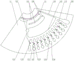
图9为图8中A部分的导流腔及其收口结构示意图;FIG. 9 is a schematic diagram of the diversion cavity and its closing structure of part A in FIG. 8;
图10为本实用新型中一个基板上设有四个基体的生物检测芯片结构示意图。10 is a schematic structural diagram of a biological detection chip with four substrates on one substrate in the present invention.
图1至图10中:In Figures 1 to 10:
101-基板、102-封装板、11-基体、110-离心旋转圆周线、111-前处理腔、112-分配腔、113-导流腔、114-加样口、115-上游导管、116- 下游导管、117-大径缓冲腔、118-废液腔、119-去杂腔、12-反应腔、 121-缓冲腔、122-限压弯管、123-毛细管、124-沉淀腔、13-排气孔、 14-收口结构。101-substrate, 102-package board, 11-base body, 110-centrifugal rotation circle, 111-pretreatment chamber, 112-distribution chamber, 113-direction chamber, 114-sample inlet, 115-upstream conduit, 116- Downstream conduit, 117-large diameter buffer chamber, 118-waste chamber, 119-decontamination chamber, 12-reaction chamber, 121-buffer chamber, 122-pressure limiting elbow, 123-capillary, 124-precipitation chamber, 13- Exhaust hole, 14-cuff structure.
具体实施方式Detailed ways
本实用新型的核心是提供一种生物检测芯片,该生物检测芯片的相关操作使用过程简便易行,无需借助额外的流体控制结构,检测效率高,适用范围广。The core of the utility model is to provide a biological detection chip, the related operation and use process of the biological detection chip is simple and easy, no additional fluid control structure is needed, the detection efficiency is high, and the application range is wide.
为了使本技术领域的人员更好地理解本实用新型方案,下面结合附图和具体实施方式对本实用新型作进一步的详细说明。In order to make those skilled in the art better understand the solution of the present invention, the present invention will be further described in detail below with reference to the accompanying drawings and specific embodiments.
请参考图1至图10,其中,图1至图4分别示出了三种实施例的生物检测芯片的结构;图5和图6分别示出了两种生物检测芯片的内部结构剖视图;图7、图8和图10分别示出了一个基板上分别设有两个基体、三个基体和四个基体的生物检测芯片结构示意图。Please refer to FIGS. 1 to 10, wherein, FIGS. 1 to 4 respectively show the structures of the biological detection chips of the three embodiments; FIGS. 5 and 6 respectively show cross-sectional views of the internal structures of the two biological detection chips; 7. FIG. 8 and FIG. 10 respectively show a schematic structural diagram of a biological detection chip with two substrates, three substrates and four substrates respectively provided on one substrate.
本实用新型提供了一种生物检测芯片,包括基体11,基体11上设置有由生物检测芯片的旋转中心沿径向向外顺次连通的前处理腔 111、分配腔112、导流腔113和反应腔12,导流腔113与反应腔12 之间连通有限压弯管122,导流腔113的上端入口的两内侧分别设计有一个向内侧延伸的收口结构14,前处理腔111上设有加样口114,基体11上还设有连通其内部各腔室与外部环境的排气孔13。The utility model provides a biological detection chip, which includes a
需要说明的是,本方案提供的生物检测芯片中,基体11及其各个腔室作为一个完整的集成反应单元,生物检测芯片还可以包括用于承载基体11的基板101,一个基板101上可以设置1个、2个、3个、4 个或更多个基体11,每个基体11代表的集成反应单元均可以独立完成一个生物检测试验,如图7、图8和图10所示,本文示出了一个基板101上分别设有2个基体11、3个基体11和4个基体11的生物检测芯片结构。基板101整体结构可以带中心孔的圆心板,或者设计为扇形、方形、椭圆形等其他结构,当基板101上设置有两个以上的基体11时,多个基体11优选地沿生物检测芯片的离心旋转圆周的周向依次布置。It should be noted that, in the biological detection chip provided by this solution, the
需要说明的是,上述基板101为圆形板结构时,其直径范围为 40~600mm,优选直径为60~150mm。基板101的材质为玻璃、硅、金属、聚合物中的一种或多种的混合物,原则上,只要能满足生物检测芯片的实际使用需求的材质均可使用。It should be noted that, when the above-mentioned
本方案可在前处理腔111内事先存储用于样品前处理的生物或化学试剂,试剂的储存形式可为液态或固态,可为液滴状、糊状、凝胶状、薄膜状、粉末状等,可为一种物质或数种物质的混合物,可置于前处理腔111的一处或多处。优选地,所述存储试剂包含有可用于样品液化及细胞和(或)病原体裂解的成分,并能够在一定条件下(比如37℃~95℃)完成样品内所含细胞及(或)病原体的裂解。所述试剂成分可包括但不限于氢氧化钠、硫酸氢钠、DTT、TCEP、异硫氰酸胍、盐酸胍、SDS、TritonX-100、吐温-20、CTAB、蛋白酶k、溶菌酶等成分中的一种或几种,以及若干种辅助成分,比如赋形剂、防腐剂等成分中的一种或几种。In this solution, biological or chemical reagents for sample pretreatment can be stored in the
本方案可在导流腔113内事先存储用于与前处理后的样品进行混合或反应的生物或化学试剂,所述试剂的储存形式可为滴状、糊状、凝胶状、薄膜状、粉末状,可为一种物质或数种物质的混合物。优选地,所述试剂包含有可用于核酸扩增反应的化学成分,包括但不限于 DNA聚合酶、RNA聚合酶、逆转录酶、重组酶、核酸切刻酶、核酸修复酶、限制性内切酶、镁离子、钾离子、dNTP、rNTP、PEG (400-20000)、BSA、TE、甜菜碱等成分中的一种或几种,以及若干种辅助成分,比如荧光染料、赋形剂、防腐剂等成分中的一种或几种。In this solution, biological or chemical reagents for mixing or reacting with the pretreated samples can be stored in the
本方案可在反应腔12内事先存储用于跟前处理后的样品进行混合或反应的生物或化学试剂,所述试剂的储存形式可为滴状、糊状、凝胶状、薄膜状、粉末状,可为一种物质或数种物质的混合物。优选地,所述试剂包含有可用于特异性核酸扩增反应或结果指示的成分,包括可与某种DNA模板特异性结合的具有特定序列或特定荧光标记的一组或多组寡核苷酸片段,以及若干种辅助成分,比如荧光染料、赋形剂、防腐剂等成分中的一种或几种。In this solution, biological or chemical reagents for mixing or reacting with previously processed samples can be stored in the
应当指出,实际操作时上述各试剂储存的方式可以是直接向各腔室内加入液态或固态物质,也可以在加入液态物质后通过自然晾干、烘干、风干、冻干等方式进行干燥固化。It should be pointed out that, in actual operation, the above-mentioned reagents can be stored by adding liquid or solid substances directly into each chamber, or drying and solidifying by natural drying, drying, air-drying, freeze-drying, etc. after adding liquid substances.
优选地,沿生物检测芯片的离心旋转圆周的径向,反应腔12的下游连通有沉淀腔124,沉淀腔124的近旋转中心端连接于反应腔12 的远旋转中心端。在反应腔12的下游连通设置有沉淀腔124是用于收集上游的反应腔12中反应后出现的固形物,以便集中收集处理,并避免这些固形物对后续的相关反应产生干扰。Preferably, along the radial direction of the centrifugal rotation circle of the biological detection chip, a
需要说明的是,本文中所述的近旋转中心端是指该部件的距离生物检测芯片的旋转中心最近的端部位置,远旋转中心端是指该部件的距离生物检测芯片的旋转中心最远的端部位置。It should be noted that the near-rotation center end described in this article refers to the end position of the component that is closest to the rotation center of the biological detection chip, and the far rotation center end refers to the component that is farthest from the rotation center of the biological detection chip. end position.
需要说明的是,本方案中的限压弯管122的形状可以使圆弧或平滑的曲线形管,也可以是折线形管,包括但不限于U型管、S型管、Ω型管、L型管等。优选地,本方案中限压弯管122的中部为U型管段,U型管段的两端分别连通有沿导流腔113的导流方向延伸的直管段,U型管段的主体直管与直管段相对倾斜。其中,导流腔113的导流方向就是导流腔113沿生物检测芯片的离心旋转圆周的径向进行引导液体流通的方向,U型管段的主体直管就是U型管主体中相互平行的两侧直管。It should be noted that the shape of the
限压弯管122的管径为0.1~1mm,优选尺寸为0.2mm。The diameter of the pressure-limiting
优选地,导流腔113与反应腔12之间连通有缓冲腔121,限压弯管122连通于缓冲腔121与导流腔113之间,且缓冲腔121与反应腔 12之间连通有毛细管123。限压弯管122能够与毛细管123协同配合,实现对导流腔113与反应腔12间试剂和样品的有效阻隔和限流,从而进一步提高相关检测反应的操作精度和可控性,同时缓冲腔121能够对经由导流腔113处通入的液体等进行有效缓冲,避免高速流动的高压液体对反应腔12主体结构产生结构冲击或其他可能会对反应过程和检测结果产生不利影响的现象,从而进一步保证检测结果的可靠性和准确性。Preferably, a
需要进一步说明的是,实际应用中可以通过调整更换不同尺寸规格的限压弯管122及毛细管123,来达到调整相应的反应腔12进料导通阈值的目的,从而满足不同工况下针对不同试验材料实施相应的检测试验。It should be further explained that, in practical applications, the purpose of adjusting the feed conduction threshold of the
优选地,分配腔112连通有多个导流腔113,每个导流腔113均通过一个限压弯管122连通有一个缓冲腔121,每个缓冲腔121均通过一个毛细管123连通有一个反应腔12。如图1至图4所示的生物检测芯片均具有10个导流腔113及10个对应的反应腔12。Preferably, the
需要说明的是,本方案中的导流腔113内可以预存试剂,从而从结构上替代现有技术中芯片的混合腔室,进而简化芯片结构,多个导流腔113内预存的试剂浓度可以一致,也可以不一样。导流腔113不仅具有定量液体的作用,更加精确定量液体体积,而且,液体分配到多个导流腔113内还可以与导流腔113内预存试剂进行混匀,其混匀效果比现有技术中集中于一个腔室内混匀的效果更好。It should be noted that the
需要说明的是,导流腔113的形状可以是正方形、矩形、三角形、圆角矩形、半圆形、半椭圆形等,也可以是上述形状的组合。导流腔 113的形状可以相同,也可以不同,其面积或容积可以相同也可以不同,达到液体均一或者非均一分配和转移目的。导流腔113上口优选设计为收口状,如图8和图9所示,导流腔113的上端入口的两内侧分别设计有一个向内侧延伸的收口结构14,进一步优选地,收口结构 14的长度小于导流腔113宽度的一半,通过设计收口结构14,可以保证在液体流入导流腔113的过程中以及液体在导流腔113内混匀过程中避免各相邻的导流腔113之间互相干扰。It should be noted that the shape of the
优选地,导流腔113沿生物检测芯片的离心旋转圆周的周向或者沿生物检测芯片的离心旋转圆周的渐开线的延伸方向依次排布,图1、图2和图7中示出了生物检测芯片的离心旋转圆周线110。当各导流腔113沿渐开线延伸排布时,可以使液体能够更加顺利、均匀地分配到每个导流腔113中,即,可以使远离上游导管115的导流腔113内更充分地分配到液体。Preferably, the
需要说明的是,分配腔112和前处理腔111之间,可以只依靠连接管道进行首尾连接,也可以依靠上下游管道组成循环连接。It should be noted that, between the
请参照图1,在一种实施例方案中,优选地,分配腔112的进料端与前处理腔111之间连通有上游导管115,且上游导管115的中部具有大径缓冲腔117。具体的,上游导管115的近旋转中心端连接于前处理腔111的远旋转中心端,以便于将前处理腔111中的液体全部转移;上游导管115的远旋转中心端连接于分配腔112的进料端,即分配腔112的近旋转中心端。大径缓冲腔117的内径大于上游导管115 的内径,大径缓冲腔117能够对由前处理腔111通入上游导管115内的液流进行适度的缓冲和导流稳压处理,以使液流能够由前处理腔111处稳定高效地通入下游分配腔112等相关腔室内。Referring to FIG. 1 , in an embodiment, preferably, an
请参照图1,在上述实施例方案中,进一步优选地,分配腔112 的近旋转中心端与前处理腔111的近旋转中心端之间连通有下游导管 116,排气孔13设置于下游导管116上。排气孔13优选设置于下游导管116的近旋转中心端。在加样过程中,下游导管116的作用是将前处理腔111内和分配腔112内以及其他相关腔室内的气体经排气孔13 排出到外部环境中;离心旋转过程中,下游导管116与上游导管115 形成完整的气路循环,以保证离心旋转的顺利进行。Referring to FIG. 1 , in the above-mentioned embodiment, preferably, a
如图1所示,通过加样口114向前处理腔111加入样品后,前处理腔111内的空气同时通过其并列连通的缓冲池和通道、以及上游导管115和分配腔112到达下游导管116,最终从排气孔13排出,然后将加样口114用带有一定粘性的膜状材料封闭。使用旋转电机等离心旋转设备提供离心旋转驱动力,将前处理腔111内的液体驱动至分配腔112内,此时,前处理腔111内的液体由于低速离心力驱动下,突破了大径缓冲腔117的阻隔作用到达了分配腔112。As shown in FIG. 1 , after the sample is added to the
请参照图3,图3为本实用新型第一实施例中的另一种生物检测芯片的结构示意图。图3中所示芯片的结构与图1所示芯片相比,其区别是导流腔113的上端入口的两侧没有设计收口结构,其他部件结构与图1相同。Please refer to FIG. 3 , which is a schematic structural diagram of another biological detection chip in the first embodiment of the present invention. Comparing the structure of the chip shown in FIG. 3 with the chip shown in FIG. 1 , the difference is that no closing structures are designed on both sides of the upper inlet of the
请参照图2,在另一种实施例方案中,下游导管116仅连接于分配腔112的近旋转中心端并且沿径向向生物检测芯片的旋转中心延伸,下游导管116的近旋转中心端开设有排气孔13,用于排出分配腔 112及相关腔室内的气体。Referring to FIG. 2 , in another embodiment, the
如图2所示,通过加样口114向前处理腔111加入样品后,使用配套装置将前处理腔111内的液体驱动转移至分配腔112内,在持续了较短的时间后,由于前处理腔111内的液体占据的空间开始减少,其内部气压开始降低,同时分配腔112内液体开始增多,其内部气压开始升高,在此过程中,虽然没有如图1的下游导管116,但是分配腔112增加的气压可以过上游导管115与前处理腔111中减小的气压进行平衡,此时分配腔112液体增加、前处理腔111内液体减少,二者之间又达到了压力平衡的状态。由于驱动力的提供是连续不断的,因此,上述平衡状态也在不断的变化,直到前处理腔111内的液体全部转移至分配腔112后,达到最终的平衡。容易理解的,其液体驱动力大小跟上游导管112的宽度负相关。根据上文所述,该驱动力只要小于由限压弯管122构成的阀门的阈值,仍能保证液体在导流腔113 进行分配,并且不提前进入反应腔12内。也可以在分配腔112上靠近旋转中心的一侧设置一个下游导管116和排气孔13,更利于将前处理腔111内的液体全部转移至分配腔112。As shown in FIG. 2 , after the sample is added to the
优选地,可对前处理腔111、大径缓冲腔117、分配腔112、导流腔113、反应腔12的内表面整体或局部地进行物理或化学处理,使其比基板材料的原始表面更加疏水,即表面疏水化处理。优选地,疏水处理后该表面与所容纳溶液的接触角为90°~140°。优选地,本方案还可以对除上述腔室外的其他腔室和管路的内壁上整体或局部地预实施表面亲水化处理,以适应不同样品或不同应用环境下的相关检测试验需求。Preferably, the inner surfaces of the
需要特别指出的是,具体到实际应用中,上述各反应腔12优选为沿以生物检测芯片的离心旋转圆周的周向延伸方向等径等距均匀分布,即,相邻两反应腔12与离心旋转设备的旋转中心的间距相等且相邻两反应腔12间的圆弧段所对应的圆心角相等,该均布结构能够有效保证各反应腔12内的样品及试剂的反应速率一致并保证反应充分进行。It should be specially pointed out that, in practical applications, the above-mentioned
优选地,分配腔112的端部连通有废液腔118。相关检测试验过程中产生的废液可以在离心力作用下经由分配腔112通入废液腔118 内,以便集中收集。废液腔118也对应设计有导流腔113,废液腔118 的导流腔113与反应腔12对应的导流腔113的容积之比大于2,以保证具有足够多的容积来容纳多余的液体。在实际应用时,可以在分配腔112的两端分别设置废液腔118,以保证废液收集效率。也可以仅在分配腔112的一端设置有废液腔118。当然,若设置多个废液腔118,则应保证各废液腔118也与各导流腔113沿同一圆弧的延伸方向排布,以保证液体导流效果。Preferably, a
废液腔118形状多样,如正方形,矩形,三角形、圆角矩形,半圆形,半椭圆形等,也可以是上述形状的组合。本方案也可以在废液腔118与导流腔113之间加入限压弯管122,防止废液回流。当分配腔112两端均设置有废液腔时,距离分配腔112的进料口一端的废液腔为去杂腔119,且该去杂腔119对应连通的导流腔113的容积小于反应腔12对应的导流腔113,且去杂腔119的容积要大于反应腔12 对应的导流腔113的容积,如此设置的目的是为了在初始低速离心旋转的时候能够将前处理腔111中带有杂质的一段液体先收集到去杂腔119对应的导流腔113内,保证有效样品试剂能够进入各个反应腔12 对应的导流腔113中,在样品分配完毕后,高速离心时,去杂腔119 再用于收集前处理腔111及上游导管115中残留的液体。The
本方案还可以在废液腔118与导流腔113之间及去杂腔119和导流腔113之间设置限压弯管122等限压连通件,以合理控制废液腔118 的导通阈值,避免本应参与检测试验相关生化反应的试剂或样品误入废液腔118内,还防止废液回流进分配腔112中。In this solution, a pressure-limiting
请参照图4,在第三种实施例方案中,优选地,基体11上设有多个前处理腔111,且各个前处理腔111由生物检测芯片的旋转中心沿径向向外顺次布置并连通。如此设置,可以实现样品的多重前处理步骤,满足多类试剂或多类样品等某些需要多重前处理的生物检验检测试验需求,以便进一步提高本方案提供的生物检测芯片的试验检测效率极其适用范围。当然,各个前处理腔111也可以并行连接,离心旋转时,各个前处理腔111同时向分配腔112转移液体,如此设置,可以使前处理腔111内的液体更加快速地转移至分配腔112中,提高检测效率。Referring to FIG. 4 , in the third embodiment, preferably, a plurality of
需要特别指出的是,对于不同的试验需求而言,可以选择在反应腔12的末端设置或不设置如上文所述的沉淀腔124,但无论是否设有该沉淀腔124,实际应用中均应保证导流腔113的体积不大于该沉淀腔124对应的下游腔室的体积之和,以保证各反应腔12内的生化反应相互独立且互不干扰。具体来说,若反应腔12的末端设置有沉淀腔 124,则应保证导流腔113的体积不大于其对应的限压弯管122、反应腔12以及沉淀腔124三者的体积之和;若反应腔12的末端未设置沉淀腔124,则应保证导流腔113的体积不大于其对应的限压弯管122 与反应腔12的体积之和;此外,无论上述何种结构和工况下,均应优选地保证导流腔113的体积大于其相对应的反应腔12的体积,以使反应更加充分,反映效果更好,检测结果更加准确可靠。It should be specially pointed out that, for different test requirements, the
需要说明的是,基体11的前处理腔111、分配腔112、反应腔12 及其附属结构(缓冲腔121、沉淀腔124、限压弯管122等)可以分别位于基板101的两侧,并依靠贯穿于基板101上的小孔进行连通。本方案生物检测芯片的主体部分为基板101,基板101两侧覆盖有封装板102,前处理腔111、分配腔112、导流腔113、反应腔12以及限压弯管122等均位于基板101与封装板102之间,且加样口114和排气孔13位于封装板102上。这种利用基板101与封装板102配合间隙形成的板间腔室结构,能够进一步提高生物检测芯片的结构集成度,优化其内部相应腔室结构的密闭性和导通效率,以使相关的生物检测反应更加充分高效。It should be noted that the
应当说明的是,实际加工制造时,基板101与封装板102之间可以采用热压、胶粘、激光焊接、超声焊接或螺纹紧固等任一种方式进行封装和紧固,以保证组件整体密封效果和装配强度。It should be noted that, during actual processing and manufacturing, the
请着重参考图5。在一种实施方案中,前处理腔111、反应腔12 以及限压弯管122均位于基板101的同一侧,且分配腔112和导流腔113位于基板101的另一侧。该种异面错位设置结构能够使得由前处理腔111、反应腔12以及限压弯管122构成的主要反应腔室与由分配腔112和导流腔113构成的主要导流腔室相对独立并各自分别封装,从而进一步提高了所述生物检测芯片的内部腔室的结构密闭性和结构集成度,且位于基板101不同侧的各相关腔室间可以通过贯穿基板101 的导孔相连通,以保证试剂和样品的顺畅流动。Please focus on Figure 5. In one embodiment, the
请着重参考图6。在另一种实施方案中,基板101的两侧均分别设置有前处理腔111、分配腔112以及导流腔113,且基板101的其中一侧设置有分别与各导流腔113连通的限压弯管122和反应腔12,并且有贯穿基板101的导孔将两侧的腔室进行连通。该种在基板101两侧均设置由前处理腔111、反应腔12以及限压弯管122构成的主要反应腔室,并将上述两套主要反应腔室分别与下游同一套由分配腔112 和导流腔113构成的主要导流腔室相连通,使得实际应用中可以将两种不同的样品或试剂分别置入位于基板101两侧的两套前处理腔111 内,并分别进行相应的前处理工序,待前处理分别完成后,再汇流于下游同一反应腔12内以便进行相应的检测反应,从而进一步提高了所述生物检测芯片的应用领域和工况适应能力,并使其操作效率和结构集成度得以进一步提高。Please focus on Figure 6. In another embodiment, both sides of the
需要说明的是,当只有基板101单侧具有液体通道时,为了保证反应腔12内的生化反应相互独立互不干扰,导流腔113的体积应小于等于反应腔12、沉淀腔124和缓冲腔121的体积之和,同时优选其体积大于反应腔12;当基板101两侧都具有液体通道时,同样为了保证反应腔12内生化反应的独立性,基板101两侧导流腔113两者的体积之和应小于等于反应腔12、沉淀腔124和缓冲腔121的体积之和,同时优选其体积大于反应腔12。It should be noted that, when only one side of the
上述基板101的材质可以为玻璃、硅片、金属或聚合物中的一种或几种的混合物,聚合物可以为PDMS(polydimethylsiloxa聚二甲基硅氧烷),PMMA(polymethylmethacrylate聚甲基丙烯酸甲酯)、PC 工程塑料、COC(copolymers of cycloolefin环烯烃共聚物)、PET (Polyethylene terephthalate聚对苯二甲酸乙二醇酯)、日本瑞翁的 COP、ABS(Acrylonitrile butadiene Styrene copolymers丙烯腈-丁二烯 -苯乙烯共聚物)中的一种或多种。The material of the
此外,基体11的外壁上覆盖有与进料口114和排气孔13贴合适配的封口膜103。该封口膜103可以对进料口114和排气孔13实施可靠密封,从而在所述生物检测芯片内部进行相关生化反应及检测时避免外部环境中的粉尘或杂质进入基体11内部腔室内,从而保证各腔室的相对密闭和密封,保证相关试验检测结果的准确可靠。In addition, the outer wall of the
需要说明的是,具体到实际应用时,考虑到不同工况下的使用操作需求,上述封口膜103可以采用透气材料,也可以采用非透气材料,工作人员可以根据实际工况灵活选择,原则上,只要是能够满足所述生物检测芯片的实际使用需要均可。It should be noted that, when it comes to practical application, considering the use and operation requirements under different working conditions, the above-mentioned sealing film 103 can be made of breathable materials or non-breathable materials, and the staff can flexibly choose according to the actual working conditions. , as long as it can meet the actual needs of the biological detection chip.
本实用新型提供的生物检测芯片的工作过程如下:The working process of the biological detection chip provided by the present invention is as follows:
将试验检测所需的相关试剂及试验样品经加样口114加入到前处理腔111中,前处理腔111中的空气通过排气孔13排出到外界环境,然后封闭加样口114。再将芯片放入辅助控制设备中进行加热温控或光照处理,处理完成后使用离心旋转设备带动生物检测芯片整体转动,使前处理腔111内的液体在离心力作用下流入分配腔112中,并分别进入各个导流腔113内,同时,分配腔112和导流腔113内的气体通过下游导管116进入前处理腔111达到压力平衡。当液体以较低的流速到达导流腔113后,尽管导流腔113和反应腔12也处于连接状态,但是,由于限压弯管122依靠自身的导通阈值形成阀门效应,此时液体压力小于阀门的阈值,因此,在非试验状态下能够阻止液体经限压弯管122进入反应腔12内。待离心旋转设备提高转速,且导流腔113 内的液体压力大于限压弯管122的导通阈值时,液体便可以进入反应腔12中进行反应,以便完成相关的生物检测操作。The relevant reagents and test samples required for test detection are added into the
实际操作时,所述生物检测芯片的具体使用方法如下:In actual operation, the specific use method of the biological detection chip is as follows:
1)通过加样口114向生物检测芯片的前处理腔111内加样;1) Add sample to the
2)将加样口114和排气孔13密封;2) Seal the
3)在配套设备的辅助下,样品在前处理腔111内与预置的试剂进行混合并反应,同时可以根据需要利用离心机等离心旋转设备带动芯片旋转,或者通过温控设备对生物检测芯片的内部各腔室的温度进行控制;3) With the assistance of the supporting equipment, the sample is mixed and reacted with the preset reagents in the
4)利用离心旋转设备对生物检测芯片实施低速离心,将步骤3) 中的液体转送至分配腔112内,并在配套设备的辅助下,使该液体与预置的试剂混合、反应,该过程同样可以根据需要控制生物检测芯片旋转,或者对各腔室内的温度进行控制;4) Low-speed centrifugation is performed on the biological detection chip by means of a centrifugal rotating device, and the liquid in step 3) is transferred to the
5)利用离心旋转设备对生物检测芯片实施高速离心,将分配腔 112内液体进一步转移至各个反应腔12内;5) using centrifugal rotating equipment to implement high-speed centrifugation on the biological detection chip, and further transfer the liquid in the
6)在配套设备的辅助下,使液体与反应腔12内预置的试剂进行反应;6) With the aid of the supporting equipment, the liquid is reacted with the preset reagent in the
7)对反应结果进行检测和分析。7) Detect and analyze the reaction results.
为便于进一步理解本方案技术内容,下面以唾液的检测为例来对本实用新型中所公开的生物检测芯片的实际操作使用作进一步详细说明。In order to further understand the technical content of this solution, the actual operation and use of the biological detection chip disclosed in the present invention will be further described in detail below by taking the detection of saliva as an example.
将唾液样本通过加样口114加入到集成化微流控芯片的前处理腔 111,腔室内预先包埋有病毒裂解试剂;之后将上述生物检测芯片(以下简称芯片)通过配套设备于37~95℃(优选65℃)温度环境下加热 1min~60min(优选30min),获得病毒核酸提取液,利用离心旋转设备在100rpm~3000rpm(优选1600rpm)转速下旋转芯片离心10sec~60sec (优选45sec),将上述病毒核酸提取液转送至导流腔113内,之后通过溶解与扩散作用,将导流腔113内预置的恒温扩增试剂与病毒核酸提取液充分混合;然后利用离心旋转设备在4500rpm转速下旋转芯片离心1min,将导流腔113内液体均匀分配至各反应腔12内,反应腔 12内预置有与样本核酸起特异性反应的引物;随后于37~95℃(优选 65℃)温度环境下对芯片加热30min~60min(优选60min),在反应腔 12内进行恒温扩增反应,最后采用配套仪器对反应腔12内的荧光进行实时检测并得出检测结果。The saliva sample is added to the
需要指出的是,上述各试验设备及环境参数仅为在一般实验条件下达到最佳的试验检测效果,各数据参数仅作举例说明之用,实际操作中,考虑到不同应用工况以及具体试验检测需求的差异,本领域技术人员可以根据实际情况灵活调整各参数的具体数值,原则上,只要是能够满足实际生物试验检测的具体需要均可。It should be pointed out that the above-mentioned test equipment and environmental parameters are only to achieve the best test results under general experimental conditions, and each data parameter is only used for illustration purposes. In actual operation, different application conditions and specific tests are considered. For differences in detection requirements, those skilled in the art can flexibly adjust the specific values of each parameter according to the actual situation. In principle, as long as it can meet the specific needs of actual biological test detection.
本实用新型具有以下有益效果:The utility model has the following beneficial effects:
1)、该生物检测芯片具有控流阀门作用的限压弯管,只需通过控制离心转速就可以实现液体的分步转移,无需借助额外的流体控制机构,操作过程简单易行,中间过程无需人工操作干预,降低了试验人员的工作量,各反应腔室内可以同步实施试验反应,实现了相关试验操作的多重处理,提高了检测效率;1) The biodetection chip has a pressure-limiting elbow that acts as a flow control valve, and the liquid can be transferred step by step only by controlling the centrifugal speed without the aid of an additional fluid control mechanism. The operation process is simple and easy, and no intermediate process is required. The manual operation intervention reduces the workload of the test personnel, and the test reactions can be carried out simultaneously in each reaction chamber, which realizes the multiple processing of related test operations and improves the detection efficiency;
2)、芯片集成度较高,结构简单,加工制造及封装成本低;2), the chip integration is high, the structure is simple, and the manufacturing and packaging costs are low;
3)、芯片检测结果准确可靠,操作过程精准可控,可广泛适用于唾液、咽拭子、宫颈拭子等多种样本类型中病毒或细胞的全自动核酸提取及多重扩增检测,不仅可以在地面环境正常工作,还可以适用于空间站等微重力环境中,大大扩展了产品的适用范围。3) The chip detection results are accurate and reliable, and the operation process is precise and controllable. It can be widely used in automatic nucleic acid extraction and multiple amplification detection of viruses or cells in various sample types such as saliva, throat swabs, and cervical swabs. It works normally in the ground environment and can also be applied to microgravity environments such as space stations, which greatly expands the scope of application of the product.
以上对本实用新型所提供的生物检测芯片进行了详细介绍。本文中应用了具体个例对本实用新型的原理及实施方式进行了阐述,以上实施例的说明只是用于帮助理解本实用新型的方法及其核心思想。应当指出,对于本技术领域的普通技术人员来说,在不脱离本实用新型原理的前提下,还可以对本实用新型进行若干改进和修饰,这些改进和修饰也落入本实用新型权利要求的保护范围内。The biological detection chip provided by the present invention has been described in detail above. The principles and implementations of the present invention are described herein by using specific examples, and the descriptions of the above embodiments are only used to help understand the method and the core idea of the present invention. It should be pointed out that for those of ordinary skill in the art, without departing from the principles of the present utility model, some improvements and modifications can also be made to the present utility model, and these improvements and modifications also fall into the protection of the claims of the present utility model. within the range.
Claims (10)
Priority Applications (1)
| Application Number | Priority Date | Filing Date | Title |
|---|---|---|---|
| CN202020123703.4U CN211586663U (en) | 2020-01-19 | 2020-01-19 | A biological detection chip |
Applications Claiming Priority (1)
| Application Number | Priority Date | Filing Date | Title |
|---|---|---|---|
| CN202020123703.4U CN211586663U (en) | 2020-01-19 | 2020-01-19 | A biological detection chip |
Publications (1)
| Publication Number | Publication Date |
|---|---|
| CN211586663U true CN211586663U (en) | 2020-09-29 |
Family
ID=72579886
Family Applications (1)
| Application Number | Title | Priority Date | Filing Date |
|---|---|---|---|
| CN202020123703.4U Active CN211586663U (en) | 2020-01-19 | 2020-01-19 | A biological detection chip |
Country Status (1)
| Country | Link |
|---|---|
| CN (1) | CN211586663U (en) |
Cited By (6)
| Publication number | Priority date | Publication date | Assignee | Title |
|---|---|---|---|---|
| CN113324985A (en) * | 2021-06-16 | 2021-08-31 | 博奥生物集团有限公司 | Centrifugal micro-fluidic detection device and centrifugal micro-fluidic detection system |
| CN113600250A (en) * | 2021-07-21 | 2021-11-05 | 华中科技大学 | Chip for micro-channel assisted high-throughput reagent quantitative distribution and analysis |
| CN114577759A (en) * | 2021-12-03 | 2022-06-03 | 北京理工亘舒科技有限公司 | An online degassing microfluidic chip and its application in the detection of novel coronavirus |
| CN115684014A (en) * | 2022-11-01 | 2023-02-03 | 广州微远医疗器械有限公司 | Microfluidic chip and its application |
| CN116337826A (en) * | 2021-12-24 | 2023-06-27 | 广州兆瑞医学生物科技有限公司 | Biological material separator |
| CN118028095A (en) * | 2024-03-29 | 2024-05-14 | 中国科学院过程工程研究所 | Nucleic acid detection device |
-
2020
- 2020-01-19 CN CN202020123703.4U patent/CN211586663U/en active Active
Cited By (8)
| Publication number | Priority date | Publication date | Assignee | Title |
|---|---|---|---|---|
| CN113324985A (en) * | 2021-06-16 | 2021-08-31 | 博奥生物集团有限公司 | Centrifugal micro-fluidic detection device and centrifugal micro-fluidic detection system |
| CN113600250A (en) * | 2021-07-21 | 2021-11-05 | 华中科技大学 | Chip for micro-channel assisted high-throughput reagent quantitative distribution and analysis |
| CN113600250B (en) * | 2021-07-21 | 2023-03-10 | 华中科技大学 | A microchannel-assisted high-throughput reagent quantitative distribution and analysis chip |
| CN114577759A (en) * | 2021-12-03 | 2022-06-03 | 北京理工亘舒科技有限公司 | An online degassing microfluidic chip and its application in the detection of novel coronavirus |
| CN116337826A (en) * | 2021-12-24 | 2023-06-27 | 广州兆瑞医学生物科技有限公司 | Biological material separator |
| CN115684014A (en) * | 2022-11-01 | 2023-02-03 | 广州微远医疗器械有限公司 | Microfluidic chip and its application |
| CN115684014B (en) * | 2022-11-01 | 2025-11-07 | 广州微远医疗器械有限公司 | Microfluidic chip and application thereof |
| CN118028095A (en) * | 2024-03-29 | 2024-05-14 | 中国科学院过程工程研究所 | Nucleic acid detection device |
Similar Documents
| Publication | Publication Date | Title |
|---|---|---|
| CN211586663U (en) | A biological detection chip | |
| CN107398307B (en) | An integrated microfluidic chip | |
| CN111760601B (en) | Microfluidic chip with integrated liquid circuit switching valve and nucleic acid detection method | |
| JP5250669B2 (en) | Microfluidic structure, pathogen detection system and method for pathogen analysis | |
| CN205797240U (en) | A kind of integrated micro-flow control chip | |
| CN108300640B (en) | Micro-fluidic chip for automatic extraction and detection of nucleic acid | |
| US20120196280A1 (en) | Microfabricated device for metering an analyte | |
| CN107129930A (en) | A kind of fully integrated detection of nucleic acids micro-fluidic chip and its application method | |
| Si et al. | A multi-volume microfluidic device with no reagent loss for low-cost digital PCR application | |
| WO2011011172A1 (en) | Microfluidic devices and uses thereof | |
| CN100537219C (en) | Method and apparatus for detecting and analyzing pathogens | |
| CN107058063A (en) | A kind of method for multiple nucleic acid amplified production fluoroscopic examination based on micro-fluidic chip | |
| TWI411779B (en) | Microfluidic bio-chip and automatic reaction detection system thereof | |
| CN108424850A (en) | A kind of centrifugal force micro-fluidic chip for nucleic acid extraction | |
| CN106554903B (en) | A kind of medicament evenly mixing device and its application method | |
| CN217739205U (en) | Micro-fluidic detection chip and sample quantitative unit thereof | |
| CN111389474B (en) | A microfluidic chip for sample dispersion and its preparation method and application | |
| CN115651807B (en) | Nucleic acid detection chip and nucleic acid detection method | |
| Chen et al. | Microfluidic system for biological agent detection | |
| Pham et al. | Fabrication of 3D continuous-flow reverse-transcription polymerase chain reaction microdevice integrated with on-chip fluorescence detection for semi-quantitative assessment of gene expression | |
| Ren et al. | Development and Challenges of Pathogen Molecular Point‐Of‐Care Testing Systems Based on Microfluidic Technology | |
| CN115418312A (en) | PCR reaction device | |
| CN207238033U (en) | Micro-fluidic chip | |
| CN219273091U (en) | Reaction chip and detection equipment | |
| CN222007789U (en) | Multi-pathogen nucleic acid detection device |
Legal Events
| Date | Code | Title | Description |
|---|---|---|---|
| GR01 | Patent grant | ||
| GR01 | Patent grant | ||
| TR01 | Transfer of patent right | ||
| TR01 | Transfer of patent right |
Effective date of registration: 20240919 Address after: 102206 No. 18, life science Road, Beijing, Changping District Patentee after: CAPITALBIO Corp. Country or region after: China Patentee after: TSINGHUA University Address before: 102206 No. 18, life science Road, Beijing, Changping District Patentee before: CAPITALBIO Corp. Country or region before: China |