CN211561372U - Infusion pump - Google Patents
Infusion pump Download PDFInfo
- Publication number
- CN211561372U CN211561372U CN201921988314.1U CN201921988314U CN211561372U CN 211561372 U CN211561372 U CN 211561372U CN 201921988314 U CN201921988314 U CN 201921988314U CN 211561372 U CN211561372 U CN 211561372U
- Authority
- CN
- China
- Prior art keywords
- pump
- infusion
- face frame
- piece
- infusion pump
- Prior art date
- Legal status (The legal status is an assumption and is not a legal conclusion. Google has not performed a legal analysis and makes no representation as to the accuracy of the status listed.)
- Active
Links
- 238000001802 infusion Methods 0.000 title claims abstract description 141
- 239000012528 membrane Substances 0.000 claims abstract description 120
- 238000012546 transfer Methods 0.000 claims abstract description 33
- XLYOFNOQVPJJNP-UHFFFAOYSA-N water Substances O XLYOFNOQVPJJNP-UHFFFAOYSA-N 0.000 claims abstract description 18
- 230000000670 limiting effect Effects 0.000 claims description 32
- 230000000694 effects Effects 0.000 claims description 21
- 238000001125 extrusion Methods 0.000 claims description 21
- 238000007789 sealing Methods 0.000 claims description 21
- 238000009434 installation Methods 0.000 claims description 8
- 210000003205 muscle Anatomy 0.000 claims description 6
- 230000002093 peripheral effect Effects 0.000 claims description 3
- 230000033001 locomotion Effects 0.000 abstract description 16
- 239000000645 desinfectant Substances 0.000 abstract description 6
- 239000007788 liquid Substances 0.000 abstract description 4
- 230000002035 prolonged effect Effects 0.000 abstract description 4
- 238000012423 maintenance Methods 0.000 description 9
- 238000004078 waterproofing Methods 0.000 description 8
- 230000000903 blocking effect Effects 0.000 description 5
- 230000002411 adverse Effects 0.000 description 2
- 230000002421 anti-septic effect Effects 0.000 description 2
- 230000005540 biological transmission Effects 0.000 description 2
- 238000004140 cleaning Methods 0.000 description 2
- 239000000356 contaminant Substances 0.000 description 1
- 238000011109 contamination Methods 0.000 description 1
- 238000013461 design Methods 0.000 description 1
- 238000002224 dissection Methods 0.000 description 1
- 239000003814 drug Substances 0.000 description 1
- 229940079593 drug Drugs 0.000 description 1
- 230000014509 gene expression Effects 0.000 description 1
- 238000012986 modification Methods 0.000 description 1
- 230000004048 modification Effects 0.000 description 1
- 230000010412 perfusion Effects 0.000 description 1
- 230000002572 peristaltic effect Effects 0.000 description 1
- 230000002265 prevention Effects 0.000 description 1
- 238000012545 processing Methods 0.000 description 1
- 230000000750 progressive effect Effects 0.000 description 1
- 238000011084 recovery Methods 0.000 description 1
- 230000003068 static effect Effects 0.000 description 1
- 238000005406 washing Methods 0.000 description 1
Images


Landscapes
- Infusion, Injection, And Reservoir Apparatuses (AREA)
Abstract
The utility model discloses an infusion pump, infusion pump are used for using with the transfer line is supporting, and the infusion pump includes casing, face frame, drive assembly, pump piece and water proof membrane, and the face frame is installed on the casing, and the face frame has the passageway of holding transfer line, and slidable mounting has a plurality of pump pieces in the face frame, and each pump piece is driven by drive assembly and reciprocating front-back motion, and the front end of pump piece is used for extrudeing the transfer line, and the water proof membrane setting is in the rear end of pump piece or set up on the drive assembly at the back of pump piece. By applying the infusion pump, the waterproof film is arranged at the rear end of the pump sheet or on the driving assembly behind the pump sheet, so that the channel for accommodating the infusion tube is separated from the driving assembly, and the potential safety hazards such as short circuit caused by liquid entering the driving assembly are avoided. Meanwhile, the waterproof membrane is arranged at the rear end of the pump sheet or on the driving assembly behind the pump sheet, so that the waterproof membrane is not easily corroded by disinfectant when the infusion pump is disinfected, the service life of the infusion pump is prolonged, and the pollution inside the infusion pump is prevented.
Description
Technical Field
The utility model relates to the technical field of medical equipment, more specifically say, relate to an infusion pump.
Background
An infusion pump is an instrument for controlling the infusion speed by acting on an infusion tube, and is often used in situations where the infusion volume and the drug quantity need to be strictly controlled.
The infusion pump generally comprises a shell, an infusion tube is arranged at the front end of the shell, and one side of the infusion tube is pressed by a pressing tube block. Install a plurality of pump pieces in the casing, the pump piece is arranged in proper order along the extending direction of transfer line, and the front end of pump piece is worn out and is acted on the transfer line by the opening on the casing, and the rear end cooperation of pump piece is provided with the cam group, and the cam rotates along with the pivot, drives and does the motion of being close to or keeping away from the transfer line with cam complex pump piece, and then changes the extrusion degree to the transfer line. The pump pieces reciprocate in respective phases by the cam, and perform peristaltic motion as a whole to perform infusion. In order to prevent liquid or disinfectant from entering the interior of the housing, a waterproof membrane is usually adhered to the opening of the housing.
However, the waterproof film is stuck to the opening, and the waterproof film is easily corroded and damaged by the disinfectant when the infusion pump is disinfected, thereby causing contamination of the infusion pump. And when the pump piece extrudes the infusion tube, the extrusion effect is transmitted through the waterproof membrane, and due to the factors such as the stress deformation of the waterproof membrane, the actual extrusion effect of the infusion tube is different from the extrusion effect output by the pump piece, so the infusion precision is poor.
SUMMERY OF THE UTILITY MODEL
In view of this, the utility model provides an infusion pump, this infusion pump's structural design can solve the easy antiseptic solution of waterproof membrane and corrode and damaged and the relatively poor problem of infusion precision effectively.
The utility model provides an infusion pump, the infusion pump is used for using with the transfer line is supporting, the infusion pump includes casing, face frame, drive assembly, pump piece and water proof membrane, the face frame install in on the casing, the face frame has the holding the passageway of transfer line, slidable mounting has a plurality of pump pieces, each in the face frame the pump piece is by drive assembly drive and reciprocating seesaw, the front end of pump piece is used for direct extrusion the transfer line, the water proof membrane sets up the rear end of pump piece or setting are in the pump piece is hou mian on the drive assembly.
By applying the infusion pump, the waterproof film is arranged at the rear end of the pump sheet or on the driving assembly behind the pump sheet, so that the potential safety hazards such as short circuit and the like caused by liquid entering the driving assembly are avoided. Meanwhile, the waterproof membrane is arranged at the rear end of the pump piece or on the driving assembly behind the pump piece, so that the waterproof membrane is not easily corroded by disinfectant when the infusion pump is disinfected, the service life of the infusion pump is prolonged, and the pollution inside the infusion pump is more reliably prevented. Meanwhile, the waterproof membrane is arranged at the rear end of the pump sheet or on the driving assembly behind the pump sheet, so that the front end of the pump sheet directly extrudes the infusion tube, the actual extrusion effect on the infusion tube is the same as the extrusion effect output by the pump sheet, the adverse effect of factors such as the stress deformation of the waterproof membrane on the infusion precision when the pump sheet extrudes the infusion tube through the waterproof membrane is avoided, and the infusion precision of the infusion pump is further improved.
In a preferred embodiment, the waterproof membrane is connected with the housing in a sealing manner, and a through hole is formed in the waterproof membrane, and the rear end of the pump blade penetrates through the through hole and is connected with the through hole in a sealing manner, or the action end of the driving assembly positioned behind the pump blade penetrates through the through hole and is connected with the through hole in a sealing manner. Because the waterproof membrane is arranged behind the pump piece, the front end of the pump piece can directly act on the infusion tube. Through the setting of through-hole, drive assembly's effect end direct drive pump piece, pump piece front end direct action has guaranteed the accurate control to transfer line extrusion again in the transfer line, and then has guaranteed the precision of infusion.
In another embodiment, the peripheral edge of the waterproof membrane is hermetically connected with the shell, the middle part of the waterproof membrane is provided with a flexible bulge, the through hole is formed in the bulge, and the rear end of the pump piece or the action end of the driving assembly is in interference fit with the through hole. Through the setting of the bulge, when the pump sheet or the action end moves back and forth, the flexible bulge can move back and forth along with the pump sheet or the action end, namely the flexible bulge provides allowance for the movement of the action end or the pump sheet, and the movement of the action end or the pump sheet is convenient. Simultaneously, provide the surplus for the removal of effect end or pump piece through flexible bulge for the transmission to the pump piece that the extrusion effect of effect end output can be accurate, and can not receive the hindrance of the hindrance effect of waterproof membrane and export and be obstructed, consequently, further guaranteed the infusion precision of this transfer pump.
The utility model also provides an infusion pump, the infusion pump is used for using with the transfer line is supporting, the infusion pump includes casing, face frame, drive assembly, pump piece and water proof membrane, the face frame has the passageway of holding the transfer line and demountable installation in on the casing, slidable mounting has a plurality ofly in the face frame the pump piece, the water proof membrane sets up the rear end of pump piece, and with casing detachable sealing connection, the last through-hole that has seted up of water proof membrane, the effect end of drive assembly passes the through-hole and rather than sealing connection, each pump piece with drive assembly detachable connection, and by drive assembly drive and reciprocating back and forth motion, the front end of pump piece is used for direct extrusion the transfer line, the relative two sets of spacing muscle that are provided with on the upper and lower lateral wall of face frame, spacing muscle is located adjacent two between the pump piece, and the distance between two opposite limiting ribs in each group is not less than the pipe diameter of the infusion pipe.
By applying the infusion pump, the waterproof membrane is not easy to be corroded by disinfectant, and the service life of the infusion pump is further prolonged. The front end of the pump sheet directly extrudes the infusion tube, thus improving the infusion precision of the infusion pump. Each part adopts a detachable structure of layer upon layer dissection, and is convenient to detach and clean. And through setting up two sets of spacing muscle, avoided too much space to occupy, simultaneously, make the transfer line can be better keep straight, further promoted the infusion precision.
Drawings
In order to more clearly illustrate the embodiments of the present invention or the technical solutions in the prior art, the drawings used in the description of the embodiments or the prior art will be briefly described below, it is obvious that the drawings in the following description are only some embodiments of the present invention, and for those skilled in the art, other drawings can be obtained according to these drawings without creative efforts.
Fig. 1 is a schematic longitudinal sectional structure view of an infusion pump according to an embodiment of the present invention;
FIG. 2 is a schematic cross-sectional view of an infusion pump;
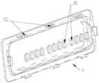
FIG. 3 is a schematic view of the mounting of the face frame and the pump blade;
FIG. 4 is a schematic longitudinal cross-sectional view of FIG. 3;
FIG. 5 is a schematic view of a waterproof membrane;
fig. 6 is a schematic view of the installation of the infusion tube.
The drawings are numbered as follows:
the device comprises a shell 1, a face frame clamping groove 11, a face frame 2, a face frame elastic buckle 21, a U-shaped clamping groove 22, a limiting rib 23, a buckle 24, a pump sheet 3, a pump sheet clamping groove 31, a blocking part 32, a waterproof membrane 4, a through hole 41, a bulge 42, a hard supporting frame 43, a flexible membrane 44, a waterproof membrane elastic buckle 45, a push rod 5, an acting end 51, a circular ring 52, a pressure pipe block 6 and a perfusion tube 7.
Detailed Description
The embodiment of the utility model discloses transfer pump to reduce the waterproof membrane and receive the corruption of antiseptic solution and the damage pollution that causes the transfer pump.
The technical solutions in the embodiments of the present invention will be described clearly and completely with reference to the accompanying drawings in the embodiments of the present invention, and it is obvious that the described embodiments are only some embodiments of the present invention, not all embodiments. Based on the embodiments in the present invention, all other embodiments obtained by a person skilled in the art without creative work belong to the protection scope of the present invention.
Referring to fig. 1-2, fig. 1 is a schematic longitudinal sectional structure view of an infusion pump according to an embodiment of the present invention; fig. 2 is a schematic cross-sectional view of an infusion pump.
In one embodiment, the present invention provides an infusion pump comprising a housing 1, a face frame 2, a drive assembly, a waterproof membrane 4, and a plurality of pump sheets 3.
Wherein, face frame 2 installs on casing 1, and face frame 2 both can be formula structure as an organic whole with casing 1, also can be fixed connection's split type structure. The face frame 2 is provided with a channel for accommodating the infusion tube 7, and the infusion tube 7 is placed in the channel when the infusion pump is used. The channel is preferably straight, so that the infusion tube 7 passes through the channel straight, and the infusion precision is guaranteed. According to the requirement, a limiting groove can be arranged on the shell 1 and matched with the channel, and the infusion tube 7 straightly passes through the infusion pump under the limiting action of the limiting groove.
The plurality of pump sheets 3 are slidably mounted in the face frame 2, and specifically, mounting holes may be respectively formed in the channel walls corresponding to the pump sheets 3, so that the pump sheets 3 are respectively slidably mounted in the mounting holes and move back and forth along the mounting holes. After the infusion tube 7 is placed in the channel, the front end of the pump piece 3 extrudes the infusion tube 7 when the pump piece 3 moves forwards. The specific number of the pump blades 3 may be set as desired, and is not particularly limited herein. As shown in the drawing, 12 pump sheets 3 may be provided, and infusion is performed by reciprocating the 12 pump sheets 3 in respective phases and peristaltically moving the whole.
The driving component is arranged behind the pump piece 3 and drives the pump piece 3 to move back and forth along the face frame 2 in a reciprocating mode. The specific structure of the drive assembly may refer to the conventional arrangement of an infusion pump and is not specifically limited herein. The driving assembly drives the pump plates 3, and particularly, the acting ends 51 of the driving assembly can be respectively connected with the pump plates 3, for example, the rear ends of the pump plates 3, so as to drive the pump plates 3 to move back and forth.
The waterproof membrane 4 is provided at the rear end of the pump blade 3 or on the drive assembly. The waterproof film 4 is used to prevent external contaminants and the like from entering the inside of the infusion pump. Specifically, the waterproof membrane 4 may be hermetically connected to the rear end of the pump blade 3 and sealed with the through hole, the waterproof membrane 4 may be hermetically connected to the driving assembly, or the waterproof membrane 4 may be hermetically connected to the face frame 2 or the housing 1 and located at the rear end of the pump blade 3.
The front end of passageway specifically can set up pressure pipe piece 6, presses pipe piece 6 to open and close, and when opening, the getting of the transfer line 7 of being convenient for is put, presses pipe piece 6 to carry on spacingly from the front end to transfer line 7 when closing, and then when pump piece 3 extrudees transfer line 7 forward, because pressure pipe piece 6 plays the supporting role to transfer line 7, pump piece 3 can play the extrusion to transfer line 7.
By applying the infusion pump, the waterproof membrane 4 is arranged at the rear end of the pump piece 3 or on the driving assembly behind the pump piece 3, so that potential safety hazards such as short circuit caused by liquid entering the driving assembly are avoided. Meanwhile, as the waterproof membrane 4 is arranged at the rear end of the pump piece 3 or on the driving component behind the pump piece 3, when the infusion pump is disinfected, the waterproof membrane 4 is not easy to be corroded by disinfectant, so that the service life of the infusion pump is prolonged, and the pollution inside the infusion pump is prevented. Meanwhile, the waterproof membrane 4 is arranged at the rear end of the pump piece 3 or on the driving component behind the pump piece 3, the front end of the pump piece 3 directly extrudes the infusion tube 7, the actual extrusion effect of the infusion tube 7 is the same as that of the output of the pump piece 3, the adverse effect of factors such as stress deformation of the waterproof membrane 4 on the infusion precision when the pump piece 3 extrudes the infusion tube 7 through the waterproof membrane 4 is avoided, and the infusion precision of the infusion pump is improved.
Specifically, the waterproof membrane 4 is connected with the casing 1 in a sealing manner, a through hole 41 is formed in the waterproof membrane 4, and the rear end of the pump blade 3 penetrates through the through hole 41 and is connected with the same in a sealing manner, or the acting end 51 of the driving assembly positioned behind the pump blade 3 penetrates through the through hole 41 and is connected with the same in a sealing manner. I.e. the waterproofing membrane 4 is provided with through holes 41 to facilitate the connection of the pump blade 3 to the drive assembly. The waterproof membrane 4 is hermetically connected to the case 1 so as to separate the front and rear ends of the waterproof membrane 4. In particular, the peripheral edge of the waterproof membrane 4 may be sealingly connected to the housing 1. In one form, the rear end of the pump blade 3 passes through the through hole 41 and is sealingly connected to the through hole 41, and the rear end of the pump blade 3 can be connected to the drive assembly for movement therewith. In another form, the actuating end 51 of the actuating assembly passes through the through-hole 41 and is sealingly connected to the through-hole 41, and the actuating end 51 of the actuating assembly can be connected to the pump blade 3 to directly actuate the movement of the pump blade 3.
By providing the waterproof film 4 behind the pump sheet 3, the front end of the pump sheet 3 can directly act on the infusion tube 7. Compared with the waterproof membrane 4 arranged at the front end of the pump piece 3, when the pump piece 3 presses the infusion tube 7, the extrusion effect is transmitted through the waterproof membrane 4, and due to factors such as the stress deformation of the waterproof membrane 4, the actual extrusion effect of the infusion tube 7 is different from the extrusion effect output by the pump piece 3. In the application, the through hole 41 is formed in the waterproof membrane 4, so that the driving assembly can directly drive the pump piece 3, the front end of the pump piece 3 directly acts on the infusion tube 7, the accurate control of the extrusion effect of the infusion tube 7 is guaranteed, and the infusion precision is further guaranteed. Preferably, the active end 51 of the drive assembly passes through and is sealingly connected to the through hole 41, so that the drive assembly is connected to the pump blade 3 with a small size, and the infusion pump is relatively small in overall size. If necessary, the waterproof film 4 may not be provided with the through hole 41, and the action end 51 of the drive unit may drive the pump sheet 3 to move through the waterproof film 4, thereby realizing the action of controlling the infusion speed of the infusion pump.
Through setting up through-hole 41 so that drive assembly is connected with pump piece 3 simultaneously, in order to prevent that waterproof membrane 4 from hindering the back-and-forth movement of drive assembly or pump piece 3, with waterproof membrane 4's all around edge and casing 1 sealing connection, waterproof membrane 4's middle part sets up to flexible swell 42, and through-hole 41 is seted up on swell 42, the rear end of pump piece 3 or drive assembly's effect end 51 and through-hole 41 interference fit. The rear end of the pump piece 3 or the action end 51 of the driving component and the waterproof membrane 4 are sealed in an interference fit mode, and the static sealing structure is simple and reliable in sealing. The specific shape and size of the bulge 42 can be set according to the stroke of the action end 51 or the pump blade 3, and is not limited herein. As shown in the drawing, the bulge 42 is cylindrical, and the through hole 41 is opened at the center of the cylinder. Or the bulge 42 may be provided in a hemispherical shape or the like. Through the arrangement of the flexible bulge 42, when the action end 51 or the pump blade 3 moves back and forth in a reciprocating manner, the flexible bulge 42 can move back and forth along with the action end 51 or the pump blade 3, namely, the flexible bulge 42 provides allowance for the movement of the action end 51 or the pump blade 3, so that the movement of the action end 51 or the pump blade 3 is facilitated. Meanwhile, the flexible bulge 42 provides allowance for the movement of the action end 51 or the pump piece 3, so that the extrusion action output by the action end 51 can be accurately transmitted to the pump piece 3 without being blocked by the blocking action of the waterproof membrane 4, and the infusion precision of the infusion pump is further ensured.
If desired, the membrane 4 is not limited to the above-mentioned configuration, such as being planar, having an edge sealingly engaging the housing 1, and the aperture 41 being in dynamic sealing engagement with the actuation end 51 of the drive assembly or the pump blade 3. On one hand, the dynamic sealing structure is complex, and on the other hand, when the driving assembly or the pump piece 3 moves back and forth, the driving assembly or the pump piece can move relative to the waterproof membrane 4, so that the friction force is large.
In the above embodiments, the driving assembly specifically includes a torque output device, a camshaft, push rods 5 and cams, the push rods 5 and the cams are disposed in one-to-one correspondence with the pump blades 3, the torque output device is connected to the camshaft to drive the camshaft to rotate, the cams are fixed on the camshaft, one end of each push rod 5 has a circular ring 52 engaged with the cam, and the other end is connected to the pump blade 3, specifically, the action end 51 of the driving assembly, and the rotation of the cam drives the push rods 5 to move back and forth in a reciprocating manner. The torque output device may be a device capable of outputting torque, such as a motor, which drives the cam shaft to rotate, and each cam fixed on the cam shaft rotates synchronously therewith. The cams are arranged corresponding to the pump blades 3 one by one, and the cams are arranged corresponding to the push rods 5 one by one, so that when the cams rotate, the push rods 5 do back and forth movement in a reciprocating manner due to the matching of the circular rings 52 of the push rods 5 and the cams, and further the push rods 5 drive the pump blades 3 to synchronously move back and forth. The driving assembly is arranged in such a way, the connection transmission is accurate and reliable, and the structure is simple and compact. The driving means is not limited to the above-described structure, and other structures capable of driving the respective pump blades 3 to reciprocate back and forth and to creep the entire body to perform the infusion may be used as necessary.
In order to facilitate the later maintenance of the infusion pump, if the interior of the infusion pump is polluted and needs to be cleaned, the waterproof membrane 4 is detachably arranged at the rear end of the pump piece 3 or on the driving assembly, and the waterproof membrane 4 can be conveniently detached, so that the parts behind the waterproof membrane 4 can be cleaned conveniently. Because waterproof membrane 4 sets up on the rear end of pump piece 3 or drive assembly, then according to concrete adapting unit, waterproof membrane 4 can directly can dismantle sealing connection with the rear end of pump piece 3, also can dismantle sealing connection with drive assembly, perhaps can dismantle sealing connection with casing 1 or can dismantle sealing connection with face frame 2.
Specifically, one of the waterproof membrane 4 and the housing 1 has a waterproof membrane elastic clip 45, and the other has a waterproof membrane clip groove capable of being engaged with the waterproof membrane elastic clip 45. When the waterproof membrane 4 is installed, the waterproof membrane 4 is installed to the waterproof membrane elastic buckle 45 and inserted into the waterproof membrane clamping groove to realize clamping, and the waterproof membrane 4 is fixed with the shell 1. When dismantling, pulling water proof membrane 4, water proof membrane elastic buckle 45 atress takes place deformation in order to deviate from in the water proof membrane draw-in groove, then takes out water proof membrane 4, and water proof membrane elastic buckle 45 is because elastic action automatic recovery deformation. By adopting the detachable connecting structure, the mounting and dismounting are convenient, and professional tools are not required. The waterproof membrane may also be detachably attached by screws or the like as required.
Further, the waterproof membrane 4 comprises a hard support frame 43 and a flexible membrane 44, the edge of the flexible membrane 44 is fixedly connected with the hard support frame 43, the hard support frame 43 is detachably connected with the shell 1, and the flexible membrane 44 is pressed on the shell 1 for sealing. The waterproof membrane 4 adopts a combined structure of a hard piece and the flexible membrane 44, and the hard support frame 43 can provide reliable support for the flexible membrane 44, so that the installation of the flexible membrane is convenient. The flexible membrane 44 is pressed against the housing 1 by the action of the rigid support frame 43 to effect a sealing action. In the case where the waterproofing membrane 4 comprises a bulge 42, the flexible membrane 44 may then comprise an edge flattening and a centrally located bulge 42, the flattened edge portion then being fixedly connected to the rigid support frame 43 by the bulge 42 to accommodate movement of the pump blade 3.
Under the condition that waterproofing membrane 4 and casing 1 can dismantle the connection through waterproofing membrane elastic buckle 45 and waterproofing membrane draw-in groove, then can set up waterproofing membrane elastic buckle 45 on the stereoplasm carriage 43, if set up waterproofing membrane elastic buckle 45 respectively in each direction of stereoplasm carriage 43, correspond on the casing 1 and set up the waterproofing membrane draw-in groove respectively.
On the basis of the above embodiments, the face frame 2 is detachably connected to the housing 1. When later maintenance is carried out, the face frame 2 can be conveniently detached from the shell 1, maintenance can be carried out without detaching the whole machine, and cleaning of the face frame 2 and all parts in the shell 1 is facilitated. The face frame 2 and the shell 1 can be connected in a detachable mode such as clamping and screw connection.
Specifically, one of the face frame 2 and the housing 1 has a face frame elastic clip 21, and the other has a face frame clip groove 11 capable of being engaged with the face frame elastic clip 21. As shown in fig. 3, fig. 3 is a schematic view illustrating the installation of the face frame and the pump sheet, specifically, the left and right sides of the face frame 2 are respectively provided with a face frame elastic buckle 21, the housing 1 is correspondingly provided with a face frame clamping slot 11, and the face frame elastic buckle 21 includes an elastic arm, and an end of the elastic arm is provided with a clamping head inserted into the face frame clamping slot 11. Realize being connected of face frame 2 and casing 1 through face frame elastic buckle 21 and face frame draw-in groove 11, when needs dismantle face frame 2, external force is scratched and is lifted face frame 2, and face frame elastic buckle 21 atress warp can be deviate from in the face frame draw-in groove 11. When the face frame 2 is installed, the face frame 2 is only required to be pushed to the installation position, when the face frame 2 moves to the face frame elastic buckle 21 and is aligned with the face frame clamping groove 11, the face frame elastic buckle 21 is inserted into the face frame clamping groove 11, and the face frame 2 is fixed in the shell 1. Therefore, the disassembly and assembly operations of the face frame 2 are simple and convenient, complex tools are not needed, the operation of maintenance personnel is convenient, the maintenance efficiency is improved, and the maintenance cost is further reduced. In order to facilitate the disassembly of the face frame 2, the front end face of the face frame 2 can be provided with a buckle 24, and the face frame 2 can be tilted out by lifting the buckle 24 during disassembly.
Further, the active end 51 of the drive assembly is detachably connected to the pump blade 3. When the face frame 2 is detached from the shell 1, the pump piece 3 and the driving assembly can be detached, the detachable structure which is dissected layer by layer is adopted, maintenance such as detaching and washing of each part in the later period can be achieved without detaching the whole machine, maintenance operation is convenient, and maintenance cost is reduced.
Specifically, the rear end of the pump plate 3 has a pump plate engaging groove 31, and the action end 51 of the drive unit engages with the pump plate engaging groove 31. The action end 51 of the driving assembly drives the pump plate 3 to move back and forth in a reciprocating manner by being engaged with the pump plate clamping groove 31. During disassembly, the pump blade 3 is pulled forward, and the action end 51 of the driving assembly is pulled out of the pump blade clamping groove 31, so that the pump blade 3 is disassembled. Pump piece 3 and drive assembly adopt the joint, directly extract pump piece 3 can dismantle, dismantle the convenience. The pump plate 3 and the driving assembly may be connected by other conventional detachable connection means such as screw connection, pin connection, etc. according to the requirement.
The pump pieces 3 are slidably mounted in the face frame 2, specifically, the face frame 2 has a plurality of mounting holes, and each pump piece 3 is slidably mounted in a corresponding mounting hole. The pump sheet 3 is limited through the mounting hole, so that the forward and backward movement of the pump sheet is more stable under the driving of the driving assembly.
To further facilitate the detachment of the pump blade 3, the front end of the pump blade 3 has a catching portion 32 that prevents the pump blade 3 from coming out of the mounting hole rearward. When the face frame 2 is detached, the face frame 2 drives the pump blade 3 to be detached from the driving assembly due to the blocking function of the blocking portion 32, that is, the pump blade 3 is detached simultaneously with the face frame 2. The face frame 2 and the pump piece 3 can be detached simultaneously by one-step operation, and the operation is simpler and more convenient. If necessary, the rear end of the pump blade 3 may be provided with a stopper 32 for preventing the pump blade 3 from coming out of the mounting hole forward, so that the pump blade 3 is limited in the mounting hole and can only move forward and backward along the mounting hole. The front and rear ends of the pump plate 3 may have flanges extending to both sides, so that when the pump plate 3 moves forward or backward along the through hole 41 to the end, the flanges abut against the face frame 2, and the pump plate 3 is confined in the through hole 41.
Specifically, as shown in fig. 3 and 4, fig. 3 is a schematic view of the installation of the face frame and the pump sheet; fig. 4 is a longitudinal sectional view of fig. 3. Grooves are respectively formed in the left side and the right side of the upper end and/or the lower end of the pump piece 3, so that the upper end and/or the lower end of the pump piece 3 are I-shaped, and through grooves, namely U-shaped clamping grooves 22, are correspondingly formed in the upper end and the lower end of the through hole 41. The boss part between the grooves on the left and right sides of the pump piece 3, i.e. the I-shaped vertical edge, slides along the through groove, and the two I-shaped horizontal edges are the blocking parts 32.
On the basis that the face frame 2 and the pump piece 3 are detachable, the waterproof membrane 4 is detachably mounted at the rear end of the pump piece 3 or on the driving component. The specific detachable installation mode can refer to the above related expressions, and the waterproof membrane 4 can also be detachably arranged, so that the waterproof membrane 4 can be conveniently detached after the face frame 2 and the pump piece 3 are detached, so that the waterproof membrane 4 and the internal area and the parts behind the waterproof membrane 4 can be conveniently maintained.
On the basis of the above embodiments, at least one set of limiting ribs 23 is oppositely arranged on the upper and lower side walls of the channel, the limiting ribs 23 are positioned between two adjacent pump blades 3, and the distance between two opposite limiting ribs 23 in each set is not less than the pipe diameter of the infusion tube 7. The limiting ribs 23 are arranged between the pump pieces 3, so that the limiting ribs 23 cannot interfere with the forward and backward movement of the pump pieces 3. The distance between the two opposite limiting ribs 23 in each group is not less than the pipe diameter of the infusion pipe 7, and when the infusion pump is used for infusion pipes 7 of different specifications, the distance between the two opposite limiting ribs 23 is not less than the pipe diameter of the infusion pipe 7 of the largest specification, so that the use of infusion pipes 7 of different specifications is met. The limiting ribs 23 are arranged between the pump pieces 3 to limit the infusion tube 7, so that the infusion tube is kept straight as much as possible, and the precision of infusion by the pump pieces 3 acting on the infusion tube 7 can be further guaranteed. Simultaneously, to the passageway front end through pressing pipe piece 6 to provide supporting role and with the pump plate 3 complex condition at passageway rear to the transfer line 7, spacing muscle 23 prevents it from deviating from with the reliable spacing of transfer line 7, has avoided pressing pipe piece 6 to push away from transfer line 7 extrusion of passageway when closing the door.
In an embodiment, the upper and lower lateral walls of the channel are oppositely provided with two sets of limiting ribs 23, and because the limiting ribs 23 are located between two adjacent pump sheets 3, the more the number of the limiting ribs 23 is, the more the width in the left-right direction is occupied, the larger the volume of the infusion pump is, and the position of the pump sheet can be occupied, and if too many limiting ribs are arranged, the efficiency of pump sheet extrusion can be influenced. Therefore, the two groups of limiting ribs 23 can effectively limit the infusion tube 7, and meanwhile, excessive space occupation is avoided, and the operation efficiency of the pump sheet is ensured. As shown in fig. 6, in the case where 12 pump blades 3 are provided, two sets of the restricting ribs 23 are provided.
Specifically, two opposite limiting ribs 23 form a V-shaped groove, and the width range of the bottom end of the V-shaped groove is 4.5-5.5 mm. It should be noted that, here, the V-shaped groove refers to that the distance between the two opposite limiting ribs 23 is gradually reduced from the front end to the rear end. The width of the bottom end of the V-shaped groove is the distance between the rear ends of the two opposite limiting ribs 23. The arrangement of the V-shaped opening plays a role in guiding the infusion tube 7 when the infusion tube 7 is installed, and the infusion tube 7 is conveniently installed in the two limiting ribs 23. The pipe diameter range of the infusion tube 7 is 3.2-4.4mm, so that the width of the bottom end of the V-shaped groove is 4.5-5.5mm, and the use requirements of different infusion tubes 7 can be met. And the width of the bottom end is set to be 4.5-5.5mm, so that the influence of error factors such as processing errors is considered, and the application range and the limiting effect of the limiting rib 23 on the infusion tube 7 are more reliable.
In one embodiment, the infusion pump is used in cooperation with an infusion tube 7, the infusion pump comprises a housing 1, a face frame 2, a driving assembly, pump sheets 3 and a waterproof membrane 4, the face frame 2 is provided with a channel for accommodating the infusion tube 7 and is detachably mounted on the housing 1, the face frame 1 is internally provided with the plurality of pump sheets 3 in a sliding manner, the waterproof membrane 4 is arranged at the rear end of each pump sheet 3, and is detachably and hermetically connected with the shell 1, the waterproof membrane 4 is provided with a through hole 41, the action end of the driving component passes through the through hole 41 and is hermetically connected with the through hole, each pump piece 3 is detachably connected with the driving component, and is driven by the driving component to reciprocate back and forth, the front ends of the pump pieces 3 are used for directly extruding the transfusion tube 7, the upper and lower side walls of the face frame are oppositely provided with two groups of limiting ribs 23, the limiting ribs 23 are positioned between the two adjacent pump pieces 3, and the distance between two opposite limiting ribs 23 in each group is not less than the pipe diameter of the infusion pipe 7. For the above embodiments, details of the detachable connection mode between the components, the specific structure of the driving assembly, and the like are not repeated herein. The infusion pump effectively solves the problems of water prevention and disassembly and cleaning, and has high infusion precision.
The embodiments in the present description are described in a progressive manner, each embodiment focuses on differences from other embodiments, and the same and similar parts among the embodiments are referred to each other.
The previous description of the disclosed embodiments is provided to enable any person skilled in the art to make or use the present invention. Various modifications to these embodiments will be readily apparent to those skilled in the art, and the generic principles defined herein may be applied to other embodiments without departing from the spirit or scope of the invention. Thus, the present invention is not intended to be limited to the embodiments shown herein but is to be accorded the widest scope consistent with the principles and novel features disclosed herein.
Claims (15)
1. The utility model provides an infusion pump, its characterized in that, the infusion pump is used for using with the transfer line is supporting, the infusion pump includes casing, face frame, drive assembly, pump piece and water proof membrane, the face frame install in on the casing, the face frame has the holding the passageway of transfer line, slidable mounting has a plurality ofly in the face frame the pump piece, each the pump piece by drive assembly drive and reciprocating seesaw, the front end of pump piece is used for direct extrusion the transfer line, the water proof membrane sets up the rear end of pump piece or setting are in the pump piece is hou mian on the drive assembly.
2. The infusion pump according to claim 1, wherein the waterproof membrane is hermetically connected to the casing, and a through hole is formed in the waterproof membrane, and a rear end of the pump sheet passes through the through hole and is hermetically connected thereto, or an active end of the driving assembly located behind the pump sheet passes through the through hole and is hermetically connected thereto.
3. The infusion pump according to claim 2, wherein the waterproof membrane is sealingly connected at its peripheral edge to the casing, and has a flexible bulge at its central portion, the through hole is provided in the bulge, and the rear end of the pump blade or the action end of the drive assembly is in interference fit with the through hole.
4. The infusion pump according to claim 2, wherein said driving assembly comprises a torque output device, a cam shaft, push rods and cams, wherein said push rods and said cams are arranged in one-to-one correspondence with each of said pump plates, said torque output device is connected with said cam shaft to drive said cam shaft to rotate, each of said cams is fixed on said cam shaft, one end of each of said push rods has a ring engaged with said cam, the other end is an acting end of said driving assembly, said cam rotates to drive said push rods to reciprocate back and forth, and said acting ends of said push rods drive said pump plates to correspondingly move back and forth.
5. The infusion pump according to claim 1, wherein the waterproof membrane comprises a rigid support frame and a flexible membrane, wherein an edge of the flexible membrane is fixedly connected with the rigid support frame, and the rigid support frame is detachably connected with the casing and presses the flexible membrane against the casing to seal the casing.
6. The infusion pump according to any one of claims 1-5, wherein said face frame is removably attached to said housing.
7. The infusion pump according to claim 6, wherein one of said face frame and said casing has a face frame elastic snap and the other has a face frame snap groove capable of being engaged with said face frame elastic snap.
8. The infusion pump of claim 6, wherein said drive assembly is removably connected to said pump blade.
9. The infusion pump of claim 8, wherein said pump blade has a blade slot at a rear end thereof, said actuation end of said drive assembly engaging said blade slot.
10. The infusion pump according to claim 8, wherein said face frame has a plurality of mounting holes, each of said pump sheets is slidably mounted in a corresponding one of said mounting holes, and a front end of said pump sheet has a stopper portion for preventing said pump sheet from being removed from said mounting holes in a rearward direction.
11. The infusion pump of claim 8, wherein said waterproof membrane is removably mounted to a rear end of said pump blade or to said drive assembly.
12. The infusion pump according to claim 11, wherein one of said waterproof membrane and said housing has a waterproof membrane elastic snap and the other has a waterproof membrane snap groove engageable with said waterproof membrane elastic snap.
13. An infusion pump according to any one of claims 1 to 5, wherein at least one set of limiting ribs is oppositely arranged on the upper and lower side walls of the channel, the limiting ribs are positioned between two adjacent pump sheets, and the distance between two opposite limiting ribs in each set is not less than the pipe diameter of the infusion tube.
14. The infusion pump according to claim 13, wherein two of said opposing limiting ribs form a V-shaped groove, and the width of the bottom end of said V-shaped groove ranges from 4.5 mm to 5.5 mm.
15. The utility model provides an infusion pump, a serial communication port, the infusion pump is used for using with the transfer line is supporting, the infusion pump includes casing, face frame, drive assembly, pump piece and water proof membrane, the face frame has the holding the passageway of transfer line and demountable installation in on the casing, slidable mounting has a plurality ofly in the face frame the pump piece, the water proof membrane sets up the rear end of pump piece, and with casing detachable sealing connection, the through-hole has been seted up on the water proof membrane, drive assembly's effect end passes the through-hole and rather than sealing connection, each the pump piece with drive assembly detachable is connected to by drive assembly drive and reciprocating ground seesaw, the front end of pump piece is used for direct extrusion the transfer line, relative being provided with two sets of spacing muscle on the upper and lower lateral wall of face frame, spacing muscle is located adjacent two between the pump piece, and the distance between two opposite limiting ribs in each group is not less than the pipe diameter of the infusion pipe.
Priority Applications (1)
| Application Number | Priority Date | Filing Date | Title |
|---|---|---|---|
| CN201921988314.1U CN211561372U (en) | 2019-11-15 | 2019-11-15 | Infusion pump |
Applications Claiming Priority (1)
| Application Number | Priority Date | Filing Date | Title |
|---|---|---|---|
| CN201921988314.1U CN211561372U (en) | 2019-11-15 | 2019-11-15 | Infusion pump |
Publications (1)
| Publication Number | Publication Date |
|---|---|
| CN211561372U true CN211561372U (en) | 2020-09-25 |
Family
ID=72531141
Family Applications (1)
| Application Number | Title | Priority Date | Filing Date |
|---|---|---|---|
| CN201921988314.1U Active CN211561372U (en) | 2019-11-15 | 2019-11-15 | Infusion pump |
Country Status (1)
| Country | Link |
|---|---|
| CN (1) | CN211561372U (en) |
Cited By (1)
| Publication number | Priority date | Publication date | Assignee | Title |
|---|---|---|---|---|
| CN113144333A (en) * | 2021-05-26 | 2021-07-23 | 深圳中科生物医疗电子有限公司 | Infusion device and infusion pump |
-
2019
- 2019-11-15 CN CN201921988314.1U patent/CN211561372U/en active Active
Cited By (2)
| Publication number | Priority date | Publication date | Assignee | Title |
|---|---|---|---|---|
| CN113144333A (en) * | 2021-05-26 | 2021-07-23 | 深圳中科生物医疗电子有限公司 | Infusion device and infusion pump |
| CN113144333B (en) * | 2021-05-26 | 2024-02-02 | 深圳中科生物医疗电子有限公司 | An infusion device and an infusion pump |
Similar Documents
| Publication | Publication Date | Title |
|---|---|---|
| EP1867349B1 (en) | Cassette clamping mechanism | |
| CN211561372U (en) | Infusion pump | |
| CN114165619A (en) | On-off mechanism and water purification equipment | |
| CN115288731B (en) | A tunnel support system | |
| CN216498005U (en) | Sewage treatment device | |
| CN213808570U (en) | One-way gear, clutch driving mechanism, pump and washing machine | |
| CN114308170A (en) | Liquid transfer device | |
| CN221879656U (en) | Peristaltic pump and dental medical instrument | |
| CN217939382U (en) | Chemical industry circulating water operation monitoring device | |
| CN218030539U (en) | Peristaltic pump capable of preventing air movement | |
| CN113261890B (en) | Cleaning robot | |
| CN217469252U (en) | High-voltage wire outlet cabinet | |
| CN211536196U (en) | Sterilizing brush for obstetrics and gynecology department | |
| CN213010117U (en) | A blanking mechanism of a dust collector | |
| CN211986534U (en) | Infusion pump | |
| CN221748689U (en) | Computer network information safety controller | |
| CN219239389U (en) | MBR membrane effluent treatment plant | |
| CN216573167U (en) | Pipetting device | |
| CN215534070U (en) | Water absorption raking device and cleaning robot | |
| CN215115321U (en) | Disposable sampling device of hydrolysis tank | |
| CN217911739U (en) | Dust hood | |
| CN223814477U (en) | Ball valve convenient to clearance dirt | |
| CN214209764U (en) | Air purification filter equipment with automatically regulated function | |
| CN220151515U (en) | Clamping type extrusion peristaltic pump | |
| CN222772329U (en) | An industrial peristaltic pump with good stability |
Legal Events
| Date | Code | Title | Description |
|---|---|---|---|
| GR01 | Patent grant | ||
| GR01 | Patent grant |