CN211291337U - Image acquisition device and image detection equipment - Google Patents
Image acquisition device and image detection equipment Download PDFInfo
- Publication number
- CN211291337U CN211291337U CN201921640216.9U CN201921640216U CN211291337U CN 211291337 U CN211291337 U CN 211291337U CN 201921640216 U CN201921640216 U CN 201921640216U CN 211291337 U CN211291337 U CN 211291337U
- Authority
- CN
- China
- Prior art keywords
- light source
- image
- camera
- image capturing
- capturing device
- Prior art date
- Legal status (The legal status is an assumption and is not a legal conclusion. Google has not performed a legal analysis and makes no representation as to the accuracy of the status listed.)
- Active
Links
- 238000001514 detection method Methods 0.000 title claims abstract description 99
- 239000011248 coating agent Substances 0.000 claims description 13
- 238000000576 coating method Methods 0.000 claims description 13
- 238000007689 inspection Methods 0.000 claims description 7
- 230000001502 supplementing effect Effects 0.000 claims description 5
- 239000011247 coating layer Substances 0.000 claims 2
- 230000008878 coupling Effects 0.000 description 16
- 238000010168 coupling process Methods 0.000 description 16
- 238000005859 coupling reaction Methods 0.000 description 16
- 238000000034 method Methods 0.000 description 12
- 238000010586 diagram Methods 0.000 description 11
- 230000008569 process Effects 0.000 description 11
- 230000006872 improvement Effects 0.000 description 10
- 230000009286 beneficial effect Effects 0.000 description 6
- 238000004519 manufacturing process Methods 0.000 description 4
- 238000000926 separation method Methods 0.000 description 4
- 230000000694 effects Effects 0.000 description 3
- 238000009434 installation Methods 0.000 description 3
- 238000012360 testing method Methods 0.000 description 3
- 230000007547 defect Effects 0.000 description 2
- 238000000605 extraction Methods 0.000 description 2
- 238000005286 illumination Methods 0.000 description 2
- 238000003709 image segmentation Methods 0.000 description 2
- 230000005540 biological transmission Effects 0.000 description 1
- 230000008859 change Effects 0.000 description 1
- 230000007812 deficiency Effects 0.000 description 1
- 230000005484 gravity Effects 0.000 description 1
- 238000003384 imaging method Methods 0.000 description 1
- 238000005259 measurement Methods 0.000 description 1
- 238000004064 recycling Methods 0.000 description 1
- 239000000758 substrate Substances 0.000 description 1
Images


Landscapes
- Investigating Materials By The Use Of Optical Means Adapted For Particular Applications (AREA)
Abstract
本申请的目的是提供一种图像采集装置及图像检测设备,其主要是由用于放置待测物的检测区的承接平台、设置于承接平台上方,并位于检测区的一侧的反射镜、设置于承接平台和反射镜的上方并用于采集检测区及反射镜所在区域的图像的第一摄像头等构成。与现有技术相比,本申请能够在简化操作,提升其检测效率的情况下,降低设备成本。
The purpose of the present application is to provide an image acquisition device and an image detection device, which are mainly composed of a receiving platform for placing the detection area of the object to be tested, a mirror arranged above the receiving platform and located on one side of the detection area, It consists of a first camera, etc., which is arranged above the receiving platform and the reflector and is used to collect images of the detection area and the area where the reflector is located. Compared with the prior art, the present application can reduce the equipment cost while simplifying the operation and improving the detection efficiency.
Description
技术领域technical field
本实用新型涉及机械领域,尤其涉及一种图像采集装置及图像检测设备。The utility model relates to the field of machinery, in particular to an image acquisition device and an image detection device.
背景技术Background technique
在回收行业中,如手机、平板电脑等电子产品在被回收后,通常需要进行外观参数、性能参数等各项检测,以判断该回收的电子产品是否具备二次出售的价值,并评估出售的价值等。In the recycling industry, after electronic products such as mobile phones and tablet computers are recycled, various tests such as appearance parameters and performance parameters are usually required to determine whether the recycled electronic products have the value of secondary sales, and to evaluate the sold electronic products. value etc.
在现有技术中,尤其是大多数电子产品在回收后,在外观参数的检测工序中,通常采用人工方式进行检测,由于人工操作存在主观差异性,极易出现漏检的情况,所以,部分厂家采用图像处理结合智能识别的方式替代人工解决相应的问题,例如,在外观参数的检测工序中,需要对电子产品不同的表面进行图像采集,然后进行图像处理,因此,需要采用多个摄像头分别进行采集电子产品不同的表面图像,以及多道工艺进行处理,操作繁琐,增加了设备和检测成本,检测效率较低。In the prior art, especially after most electronic products are recycled, in the inspection process of appearance parameters, the inspection is usually carried out manually. Due to subjective differences in manual operation, it is very easy to miss the inspection. Therefore, some Manufacturers use image processing combined with intelligent recognition to replace manual solutions. For example, in the inspection process of appearance parameters, it is necessary to collect images on different surfaces of electronic products, and then perform image processing. Therefore, multiple cameras need to be used separately. Collecting different surface images of electronic products and processing with multiple processes is cumbersome to operate, increases equipment and inspection costs, and has low inspection efficiency.
因此,如何在简化操作,提升其检测效率的情况下,降低设备成本,是本申请急需解决的技术问题。Therefore, how to reduce the equipment cost while simplifying the operation and improving the detection efficiency is a technical problem that needs to be solved urgently in the present application.
实用新型内容Utility model content
针对上述现有技术的缺点或不足,本实用新型要解决的技术问题是提供一种图像采集装置及检测设备,能够在简化操作,提升其检测效率的情况下,降低设备成本。In view of the above-mentioned shortcomings or deficiencies of the prior art, the technical problem to be solved by the present invention is to provide an image acquisition device and a detection device, which can reduce the cost of the device while simplifying the operation and improving the detection efficiency.
为解决上述技术问题,本实用新型提供了一种图像采集装置,包括:In order to solve the above technical problems, the utility model provides an image acquisition device, including:
承接平台,具有用于放置待测物的检测区;The receiving platform has a detection area for placing the object to be tested;
反射镜,设置于所述承接平台上方,并位于所述检测区的一侧,用于显示所述待测物的侧面图像;a reflector, arranged above the receiving platform and located on one side of the detection area, for displaying the side image of the object to be tested;
第一摄像头,设置于所述检测区和所述反射镜的上方,用于采集所述检测区及所述反射镜所在区域的图像。The first camera is arranged above the detection area and the reflection mirror, and is used for collecting images of the detection area and the area where the reflection mirror is located.
进一步作为优选地,所述承接平台包括:用于安装所述反射镜的底板;其中,所述底板上有部分凸起形成与所述检测区的形状相匹配的凸起部。Further preferably, the receiving platform includes: a bottom plate for installing the reflector; wherein, there are some protrusions on the bottom plate to form protrusions matching the shape of the detection area.
进一步作为优选地,所述凸起部有部分被镂空形成与检测区的形状相匹配的镂空部;所述承接平台还包括:用于盖合所述镂空部并用于放置待测物的承接板。Further preferably, a portion of the raised portion is hollowed out to form a hollowed-out portion matching the shape of the detection area; the receiving platform further comprises: a receiving plate for covering the hollowed-out portion and for placing the object to be tested .
进一步作为优选地,所述承接板为透明面板。Further preferably, the receiving plate is a transparent panel.
进一步作为优选地,所述反射镜为多个,且沿所述检测区的周向布局设置;所述第一摄像头的拍摄方向垂直或接近垂直所述检测区。Further preferably, there are multiple mirrors, and they are arranged along the circumferential layout of the detection area; the shooting direction of the first camera is perpendicular or nearly perpendicular to the detection area.
进一步作为优选地,各反射镜首尾依次相连,且围合形成的区域为检测区。Further preferably, the mirrors are connected end to end in sequence, and the enclosed area is the detection area.
进一步作为优选地,所述反射镜的数量为四个,且两两相对设置。Further preferably, the number of the mirrors is four, and they are arranged opposite to each other.
进一步作为优选地,所述反射镜为平面镜或弧面镜。Further preferably, the reflecting mirror is a plane mirror or a curved mirror.
进一步作为优选地,所述检测区的形状为正方形、长方形、圆形中的任意一种。Further preferably, the shape of the detection area is any one of square, rectangle and circle.
进一步作为优选地,反射镜本体、用于固定所述反射镜本体的固定板、与所述固定板相连的转动板、用于与所述转动板活动连接的反射镜支架。Further preferably, a reflector body, a fixed plate for fixing the reflector body, a rotating plate connected with the fixed plate, and a reflector support for movably connected with the rotating plate.
进一步作为优选地,所述反射镜本体的形状为透明的多面棱柱体,且所述多面棱柱体有一棱面涂有镜面涂层,且该镜面涂层与所述固定板相贴。Further preferably, the shape of the mirror body is a transparent multi-faceted prism, and one face of the multi-faceted prism is coated with a mirror coating, and the mirror coating is attached to the fixing plate.
进一步作为优选地,所述多面棱柱体为三棱柱体。Further preferably, the polyhedral prism is a triangular prism.
进一步作为优选地,所述三棱柱体的截面形状为等腰直角三角形。Further preferably, the cross-sectional shape of the triangular prism is an isosceles right triangle.
进一步作为优选地,所述反射镜支架包括:用于活动连接相邻的两个反射镜本体的连接件、用于将所述反射镜本体与所述连接件锁紧连接的锁紧件;其中,所述反射镜本体在所述连接件上转动至预设角度后被所述锁紧件锁紧。Further preferably, the mirror support includes: a connecting piece for movably connecting two adjacent mirror bodies, a locking piece for lockingly connecting the mirror body and the connecting piece; wherein , the mirror body is locked by the locking piece after being rotated on the connecting piece to a preset angle.
进一步作为优选地,所述连接件包括:开设有第一滑槽的第一本体、与所述第一本体相连并开设有第二滑槽的第二本体、与其中一个反射镜相连并插入所述第一滑槽的第一转轴、与另一个反射镜相连并插入所述第二滑槽的第二转轴;所述锁紧件包括:用于分别与所述第一转轴和所述第二转轴锁紧连接的锁紧螺母。Further preferably, the connector includes: a first body with a first chute, a second body connected with the first body and with a second chute, connected with one of the mirrors and inserted into all the mirrors. the first rotating shaft of the first chute, and the second rotating shaft that is connected to another reflector and inserted into the second chute; the locking member includes: The lock nut of the shaft locking connection.
进一步作为优选地,所述连接件包括:与所述第一本体和所述第二本体相连并与所述承接平台可拆卸连接的第三本体。Further preferably, the connector includes: a third body connected to the first body and the second body and detachably connected to the receiving platform.
进一步作为优选地,所述第一滑槽和所述第二滑槽均为弧形槽。Further preferably, the first chute and the second chute are arc-shaped grooves.
进一步作为优选地,所述反射镜的镜面涂层与所述承接平台之间的夹角为15度到30度。Further preferably, the included angle between the mirror coating of the reflector and the receiving platform is 15 degrees to 30 degrees.
进一步作为优选地,所述夹角为20度。Further preferably, the included angle is 20 degrees.
进一步作为优选地,还包括:设置于所述承接平台上方的N组第一光源灯,用于对所述待测物进行补光,其中,所述N为正整数。Further preferably, it also includes: N groups of first light source lamps arranged above the receiving platform, used to fill light on the object to be tested, wherein the N is a positive integer.
进一步作为优选地,每组中的所述第一光源灯为多个,位于所述反射镜的上方,且在垂直于所述第一摄像头的拍摄方向的平面围绕设置。Further preferably, there are a plurality of the first light source lamps in each group, located above the reflector, and arranged around a plane perpendicular to the shooting direction of the first camera.
进一步作为优选地,所述第一光源灯围绕的区域的形状为正方形、长方形、圆形中的任意一种。Further preferably, the shape of the area surrounded by the first light source lamp is any one of a square, a rectangle, and a circle.
进一步作为优选地,所述第一光源灯为矩形面光源,且每组中第一光源灯的数量为四个,两两相对设置。Further preferably, the first light source lamps are rectangular surface light sources, and the number of the first light source lamps in each group is four, which are arranged opposite to each other.
进一步作为优选地,所述N等于2,且相邻的两组第一光源灯从下至上间隔设置。Further preferably, the N is equal to 2, and adjacent two groups of first light source lamps are arranged at intervals from bottom to top.
进一步作为优选地,还包括:用于固定所述第一光源灯的第一支架,且所述第一支架具有用于所述第一摄像头拍摄所述检测区和所述反射镜的镂空区;用于活动连接所述第一光源灯与所述第一支架的联结件;用于将所述第一光源灯与所述联结件锁紧连接的锁止件;其中,所述第一光源灯在所述联结件上转动至预设角度后被所述锁止件锁紧。Further preferably, it also includes: a first bracket for fixing the first light source lamp, and the first bracket has a hollow area for the first camera to photograph the detection area and the reflector; A connecting piece for movably connecting the first light source lamp and the first bracket; a locking piece for lockingly connecting the first light source lamp and the connecting piece; wherein, the first light source lamp It is locked by the locking member after being rotated to a preset angle on the coupling member.
进一步作为优选地,还包括:第二摄像头,设置于所述承接平台的下方,用于采集所述检测区所在区域的图像;所述检测区至少有部分为透明区域,所述透明区域用于放置所述待测物;其中,所述第二摄像头与所述第一摄像头相对设置,且所述第一摄像头的拍摄方向垂直或接近垂直所述检测区。Further preferably, it also includes: a second camera, arranged below the receiving platform, for collecting images of the area where the detection area is located; at least part of the detection area is a transparent area, and the transparent area is used for The object to be tested is placed; wherein, the second camera is arranged opposite to the first camera, and the shooting direction of the first camera is vertical or nearly vertical to the detection area.
进一步作为优选地,还包括:设置于所述承接平台下方的M组第二光源灯,用于对所述待测物进行补光,其中,所述M为正整数。Further preferably, it also includes: M groups of second light source lamps arranged below the receiving platform, used to fill light on the object to be tested, wherein the M is a positive integer.
进一步作为优选地,每组中的第二光源灯为多个,位于所述检测区的下方,且在垂直于所述第二摄像头的拍摄方向的平面围绕设置。Further preferably, there are multiple second light source lamps in each group, located below the detection area, and arranged around a plane perpendicular to the shooting direction of the second camera.
进一步作为优选地,所述第二光源灯围绕的区域的形状为正方形、长方形、圆形中的任意一种。Further preferably, the shape of the area surrounded by the second light source lamp is any one of a square, a rectangle, and a circle.
进一步作为优选地,所述第二光源灯为矩形面光源,且每组中第二光源灯的数量为四个,两两相对设置。Further preferably, the second light source lamps are rectangular surface light sources, and the number of the second light source lamps in each group is four, which are arranged opposite to each other.
进一步作为优选地,所述M等于2,且相邻的两组第二光源灯从上至下间隔设置。Further preferably, the M is equal to 2, and two adjacent groups of second light source lamps are arranged at intervals from top to bottom.
进一步作为优选地,还包括:用于固定所述第二光源灯的第二支架,且所述第二支架具有用于所述第二摄像头拍摄所述检测区的镂空部;用于活动连接所述第二光源灯与所述第二支架的联结件;用于将所述第二光源灯与所述联结件锁紧连接的锁止件;其中,所述第二光源灯在所述联结件上转动至预设角度后被所述锁止件锁紧。Further preferably, it also includes: a second bracket for fixing the second light source lamp, and the second bracket has a hollow part for the second camera to photograph the detection area; a coupling piece between the second light source lamp and the second bracket; a locking piece for lockingly connecting the second light source lamp and the coupling piece; wherein the second light source light is on the coupling piece After being rotated up to a preset angle, it is locked by the locking member.
本申请还提供了一种图像检测设备,包括可形成密闭环境的箱体,上述的图像采集装置,且所述图像采集装置封闭设置于所述箱体内。The present application also provides an image detection device, comprising a box body capable of forming a closed environment, the above-mentioned image acquisition device, and the image acquisition device is closed and disposed in the box body.
进一步作为优选地,所述承接平台可滑动地设置于所述箱体内;所述箱体上开设有用于滑出所述承接平台的窗口;其中,承接平台的一侧壁用于封闭该窗口。Further preferably, the receiving platform is slidably arranged in the box body; the box body is provided with a window for sliding out of the receiving platform; wherein, a side wall of the receiving platform is used to close the window.
进一步作为优选地,还包括:与所述第一摄像头电连接并位于所述箱体内的图像处理装置;所述承接平台将所述箱体内部分成上腔体和下腔体;所述上腔体内设有所述第一摄像头和所述反射镜;所述下腔体内设有与所述图像处理装置电连接的第二摄像头。Further preferably, it also includes: an image processing device that is electrically connected to the first camera and located in the box; the receiving platform divides the box into an upper cavity and a lower cavity; the upper cavity The first camera and the reflector are arranged inside the body; the lower cavity is arranged with a second camera that is electrically connected to the image processing device.
进一步作为优选地,还包括:将所述第一摄像头悬挂于所述箱体内的第一基梁、将所述第二摄像头倒挂于所述箱体内的第二基梁;所述第一摄像头可活动地设置于第一基梁上;所述第二摄像头可活动地设置于第二基梁上。Further preferably, it also includes: hanging the first camera on the first base beam in the box, hanging the second camera upside down on the second base beam in the box; the first camera can be The second camera is movably arranged on the first base beam; the second camera is movably arranged on the second base beam.
进一步作为优选地,第一支架和第一光源灯设置于所述上腔体内;第二支架和第二光源灯设置于所述下腔体内;所述第一支架和所述第二支架均与所述箱体的侧壁相连,且可沿所述箱体的高度方向滑动调节设置。Further preferably, the first bracket and the first light source lamp are arranged in the upper cavity; the second bracket and the second light source lamp are arranged in the lower cavity; The side walls of the box body are connected and can be slidably adjusted along the height direction of the box body.
进一步作为优选地,还包括:设置于所述箱体内的轨道、与所述承接平台相连用于滑动连接所述轨道的滑轨、设置于所述箱体内用于驱动所述承接平台滑动的驱动电机、与驱动电机的驱动轴相连并用于驱动所述承接平台滑动的驱动杆、与所述驱动杆和所述承接平台的侧壁相连的固定件。Further preferably, it also includes: a track arranged in the box, a slide rail connected to the receiving platform for slidingly connecting the track, and a drive arranged in the box for driving the bearing platform to slide. A motor, a drive rod connected with the drive shaft of the drive motor and used for driving the receiving platform to slide, and a fixing piece connected with the driving rod and the side wall of the receiving platform.
进一步作为优选地,所述驱动杆为丝杠;所述固定件的一端套设在丝杆上,而另一端与所述承接平台相连;其中,当所述丝杆正向转动时,所述固定件推动所述承接平台朝所述窗口的外侧移动。Further preferably, the drive rod is a lead screw; one end of the fixing member is sleeved on the lead screw, and the other end is connected to the receiving platform; wherein, when the lead screw rotates forwardly, the The fixing member pushes the receiving platform to move toward the outside of the window.
进一步作为优选地,还包括:设置于所述箱体的外壁的一显示屏,且所述显示屏与所述图像采集装置电性连接。Further preferably, it also includes: a display screen disposed on the outer wall of the box, and the display screen is electrically connected with the image capturing device.
进一步作为优选地,所述显示屏为触控显示屏。Further preferably, the display screen is a touch display screen.
与现有技术相比,本申请能够能够在简化操作,提升其检测效率的情况下,降低设备成本。Compared with the prior art, the present application can reduce the equipment cost while simplifying the operation and improving the detection efficiency.
附图说明Description of drawings
通过阅读参照以下附图所作的对非限制性实施例所作的详细描述,本申请的其它特征、目的和优点将会变得更明显:Other features, objects and advantages of the present application will become more apparent by reading the detailed description of non-limiting embodiments made with reference to the following drawings:
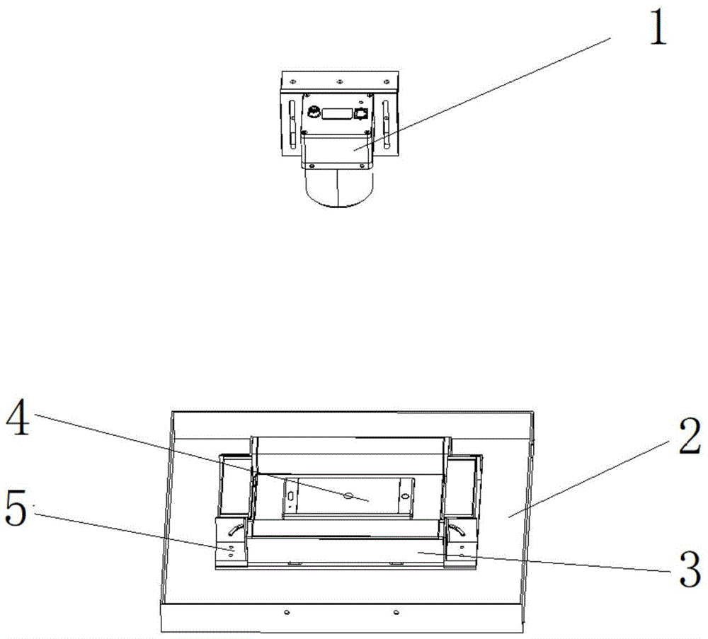
图1:本实用新型第一实施例中图像采集装置的结构示意图;Figure 1: a schematic structural diagram of an image acquisition device in the first embodiment of the present invention;
图2:本实用新型第一实施例中承接平台的结构示意图;Fig. 2: the structural representation of the receiving platform in the first embodiment of the present utility model;
图3:本实用新型第一实施例中底板的结构示意图;Fig. 3: the structural representation of the bottom plate in the first embodiment of the present utility model;
图4:图1中反射镜的结构示意图;Figure 4: Schematic diagram of the structure of the mirror in Figure 1;
图5:本实用新型第二实施例中图像采集装置的结构示意图;Figure 5: a schematic structural diagram of an image acquisition device in the second embodiment of the present invention;
图6:本实用新型第二实施例中联结件和第一支架结合后的结构示意图;Fig. 6: The structural schematic diagram after the coupling piece and the first bracket are combined in the second embodiment of the present invention;
图7:本实用新型第二实施例中第一光源灯的结构示意图;Figure 7: a schematic structural diagram of the first light source lamp in the second embodiment of the present invention;
图8:本实用新型第二实施例中第一光源灯和第一支架结合后的结构示意图;Figure 8: a schematic structural diagram of the combination of the first light source lamp and the first bracket in the second embodiment of the present invention;
图9:本实用新型第三实施例中图像采集装置的正面结构示意图;Fig. 9: The front structure schematic diagram of the image acquisition device in the third embodiment of the present invention;
图10:本实用新型第四实施例中图像采集装置的侧面结构示意图;Figure 10: a schematic side view of the image acquisition device in the fourth embodiment of the present invention;
图11:本实用新型第五实施例中图像检测设备的关闭状态示意图;Figure 11: A schematic diagram of the closed state of the image detection device in the fifth embodiment of the present invention;
图12:本实用新型第五实施例中图像检测设备的打开状态示意图;Fig. 12: A schematic diagram of the open state of the image detection device in the fifth embodiment of the present invention;
图13:本实用新型第六实施例中图像检测设备的内部结构示意图;Figure 13: A schematic diagram of the internal structure of the image detection device in the sixth embodiment of the present invention;
图14:本实用新型第六实施例中图像检测设备的内部结构的正面示意图;Figure 14: a schematic front view of the internal structure of the image detection device in the sixth embodiment of the present invention;
图15:本实用新型第七实施例中图像检测设备的内部结构的侧面示意图;Figure 15: a schematic side view of the internal structure of the image detection device in the seventh embodiment of the present invention;
图16:本实用新型第七实施例中图像检测设备的外部结构示意图;16: A schematic diagram of the external structure of the image detection device in the seventh embodiment of the present invention;
附图标记说明:第一摄像头1、承接平台2、反射镜3、待测物4、连接件5、第一光源灯6、第一支架7、联结件8、第二摄像头9、第二光源灯10、第二支架11、联结件12、箱体13、第一基梁14、第二基梁15、吊环16、支撑脚17、轨道18、滑轨19、承接板21、底板22、把手23、安装基板24、凸起部221、内缘面2211、镂空部222、第一本体51、第一滑槽511、第二本体52、第二滑槽521、第三本体53、反射镜本体31、固定板32、转动板33、转孔331、垂直部81、水平部82、圆弧槽83、底座61、轴孔611、灯体62、光源调整条101、光源固定条102、驱动杆103、驱动电机104、固定件105、光源控制器106、工控机107、窗口130、上腔体131、下腔体132、上柜门、133、下柜门134、显示屏135、槽体1011、固定片1012、调整片1013。Description of reference numerals:
具体实施方式Detailed ways
以下将结合附图对本实用新型的构思、具体结构及产生的技术效果作进一步说明,以充分地了解本实用新型的目的、特征和效果。The concept, specific structure and technical effects of the present utility model will be further described below in conjunction with the accompanying drawings, so as to fully understand the purpose, characteristics and effects of the present utility model.
实施例一Example 1
本实施例提供了一种图像采集装置,应用于箱体13,或理想的采光环境,如开放的室内外空间,或可封闭的暗室内,用于检测待测物4,尤其是电子产品的外观,如图1所示,该图像采集装置主要是由用于放置待测物4的检测区的承接平台2、设置于承接平台2上方并位于检测区的一侧的反射镜3、设置于承接平台2和反射镜3的上方并用于采集检测区及反射镜3所在区域的图像的第一摄像头1等构成。This embodiment provides an image acquisition device, which is applied to the
通过上述结构可知,当待测物4,如手机、平板电脑等电子产品放置于承接平台2上时,通过反射镜3实时显示待测物4的侧面图像,因此借助反射镜3的配合,使得图像采集装置采用单个摄像头即可拍摄待测物4的正面图像和侧面图像,而无须通过设置多个摄像头来拍摄待测物4的图像,因此简化了结构,降低了设备成本。此外,通过单张图像即可获取待测物4的正面及侧面信息,有利于简化图像处理的流程,即简化操作,提高检测的效率,便于后续识别待测物4的各项外观特征,如疵点、刮痕等。It can be seen from the above structure that when the object to be tested 4, such as a mobile phone, tablet computer and other electronic products are placed on the receiving
具体地,如图1所示,本实施例中的反射镜3优选为多个,且围绕检测区的周向布局设置。因此,当待测物4放置于检测区内时,通过该设置结构实现对待测物4的侧部不同角度的测量,如东南西北四个方向,避免有一侧出现遗漏,无须二次拍摄,便于后续的检测。显然,本实施例中的反射镜3 的数量可以根据实际需求,例如仅需检测待测物4的一侧面图像,或两侧面图像,设置为一个、两个或三个等其他数量的,又或者通过一个环形的反射镜3显示待测物4的侧面图像。因此,本实施例对反射镜3的具体数量不作过多的赘述。Specifically, as shown in FIG. 1 , there are preferably
如图1所示,作为优选地,第一摄像头1的拍摄方向大体上垂直检测区,如垂直或略微带一定的倾斜角度垂直于检测区,以使得第一摄像头1拍摄的正面图像及侧面图像较为理想,避免出现畸形的现象,不利于后续的图像特征识别。As shown in FIG. 1 , preferably, the shooting direction of the
作为较佳的一种优选方式,如图2所示,本实施例中的各反射镜3可首尾依次相连,围合形成的区域为检测区。通过该设置方式使得反射镜3尽可能地对待测物4的侧部,即其周向形成全方位的包围,避免待测物4的侧部有部分区域,以及倒角区域未显示在反射镜3中,从而避免出现漏检的情形。当然,本实施例中的反射镜3为多个时,也可以为间隔围绕设置的,仅需保持反射镜 3的长度大于待测物4的长度或宽度即可。As a better preferred manner, as shown in FIG. 2 , the
如图1所示,本实施例中的反射镜3的数量优选为四个,且两两相对设置。以从待测物4的前后左右四个方向获取待测物4的图像。反射镜3可以优选为平面镜,以较好地反映待测物4的侧部,并防止出现镜中的成像出现变形的现象。As shown in FIG. 1 , the number of the reflecting
另外,本实施例中的反射镜3也可以根据实际需求设计为弧面镜,以匹配侧部为弧面的待测物4,使得摄像头获取的图像中待测物4的长度更接近待测物4自身的长度。In addition, the
如图2所示,承接平台2可以由用于安装反射镜3的底板22等构成。其中,底板22上有部分凸起形成与检测区的形状相匹配的凸起部221等构成。由此可知,通过凸起部221使得放置待测物4的检测区可略高于反射镜3的底部,可保证待测物4的侧面能够最大限度低显示在反射镜3中。As shown in FIG. 2 , the receiving
作为优选的方式,为了降低制造成本,凸起部221有部分被镂空形成与检测区的形状相匹配的镂空部222;承接平台2还包括:用于盖合镂空部222 并用于放置待测物4的承接板21。通过承接板21和镂空部222之间的可拆解联结,降低了底板22的制造工艺,便于拆解和更换。As a preferred way, in order to reduce the manufacturing cost, a part of the raised
作为优选地,本实施例中的承接板21为透明面板,以使得检测区成为了透明区,方便后续通过摄像头从承接板21的背面拍摄待测物4的图像。此外,通过凸起部221和承接板21之间的连接结构,使得承接平台2无须整个检测区为透明区,仅使得承接板21所在区域为透明区即可,降低了生产和制造成本。Preferably, the receiving
此外,为了便于承接平台2在箱体13内或相应的支架上的固定,承接平台2还包括:与底板22固定连接的安装基板24。并且,安装基板24可优选采用开设有镂空区(图中未示出),以用于匹配底板22的镂空部222,从而便于后续通过摄像头从承接板21的背面拍摄待测物4的图像。In addition, in order to facilitate the fixing of the receiving
如图3所示,镂空部222的边缘有部分内凹形成内缘面2211,以通过内缘面2211放置承接板21,实现凸起部221和承接板21之间的卡合。显然,本实施例中的承接板21和凸起部221也可以是一体成型,在此不作赘述。As shown in FIG. 3 , the edge of the
详细地,本实施例中的检测区的形状优选为正方形、长方形、圆形中的任意一种。通过检测区的形状与待测物4的轮廓相适配,防止待测物4侧部的部分区域与反射镜3不平行而导致反射镜3中所成的像存在变形的现象,利于后续的特征识别。如图2所示,本实施例仅以优选为长方形为例作简要说明,以匹配手机、平板等大多数电子产品的形状。由于检测区为长方形,因此当长方形的待测物4放置于长方形中,各反射镜3与待测物4之间的距离大致相同,可较好的保证各反射镜3所成的像位于第一摄像头1的景深内,以避免出现第一摄像头1采集的图像中各反射镜3所显示的像无法同时保持清晰。并且,本实施例中的反射镜3为两个长边反射镜3,以及两个短边反射镜3,并仅以此为例说明。当然,反射镜3也可以根据实际的需求设计为同样长度的,在此不作赘述。In detail, the shape of the detection area in this embodiment is preferably any one of a square, a rectangle, and a circle. By adapting the shape of the detection area to the outline of the object to be tested 4, it prevents the partial area of the side of the object to be tested 4 from being parallel to the
在本实施例中,反射镜3可以位于承接平台2上方,也可以是其底部与承接平台2相连,而本实施例仅以反射镜3与承接平台2相连相连为例作说明,以利于利于光线的聚集,避免出现漏光,导致反射镜3中形成的像中出现亮斑,以及其他的背景干扰物,便于后续图像处理过程中,待测物4与背景图像的分离。In this embodiment, the
另外,如图2和图4所示,本实施例中的反射镜3可以由反射镜本体31、用于固定反射镜本体31的固定板32、与固定板相连的转动板33、与转动板活动连接的反射镜支架等构成。因此,通过该结构可方便地调节反射镜本体31 的转动角度。In addition, as shown in FIG. 2 and FIG. 4 , the
并且,转动板33上开设有转孔331,在实际使用中,通过在转孔331中插入相应的转轴即可带动转动板33,从而实现反射镜3的角度调节。In addition, the rotating
此外,如图4所示,开设在转动板33上的转孔331至少为两个,其中,一个为轴心孔,另一个为转轴孔。其中,反射镜3在转动时,围绕插入轴心孔的中心轴转动,并且通过插入转轴孔的转轴带动反射镜3的调节,籍此,实现了反射镜3的圆周转动,方便了射镜的反射角度的精准控制。其中,本实施例中的转轴孔优选为两个,且位于同一圆周上。In addition, as shown in FIG. 4 , there are at least two
并且,如图4所示,反射镜本体31的形状为透明的多面棱柱体,且多面棱柱体有一棱面涂有镜面涂层311,且该镜面涂层311与固定板32相贴。因此,通过该镜面涂层可较好地将待测物的图像反射至摄像头中。Moreover, as shown in FIG. 4 , the shape of the
进一步作为优选地,各反射镜3的镜面涂层311与承接平台2之间的夹角为15度到30度。通过该夹角的角度设置,使得反射镜3中所呈现的像可以清晰地显示。较佳地,该夹角优选为20度,以获得理想的成像效果。Further preferably, the included angle between the
如图4所示,反射镜本体31的形状优选为透明的三棱柱体,以通过三棱柱体使得反射镜本体31的棱边的转动轨迹为圆形,缩小了三棱柱体的截面在轨迹中的占据面积,使得反射镜面32的面积达到最大化,利于第一摄像头1 的图像采集。此外,需要说明的是,反射镜本体31的形状也可以根据实际情况设计为其他多面体的棱柱体,如四棱柱体、五棱柱体等,在此不作过多的赘述。As shown in FIG. 4 , the shape of the
此外,本实施例中的转动板33优选为两个,且封闭反射镜本体31的相对两端,以防止光线从反射镜本体31的相对两端射入,从而避免镜面涂层311 中的图像受到其他光线的干扰。In addition, the number of
进一步作为优选地,三棱柱体的截面形状为等腰直角三角形。以使得反射镜本体31的两外两个棱面刚好相互垂直,便于摄像头从上至下获取镜面涂层中所反射的图像。Further preferably, the cross-sectional shape of the triangular prism is an isosceles right triangle. In order to make the two outer and two facets of the
此外,值得一提的是,本实施例中,转动板33与反射镜本体31相贴的侧壁涂有挡光涂层,如黑色涂层等,以防止光线从反射镜本体31的相对两端射入,从而避免镜面涂层311中的图像受到其他光线的干扰。In addition, it is worth mentioning that, in this embodiment, the side wall of the
另外,如图2所示,反射镜支架可以由用于活动连接相邻的两个反射镜本体31的连接件5、用于将反射镜本体31与连接件5锁紧连接的锁紧件等构成。其中,反射镜本体31在连接件5上转动至预设角度后被锁紧件锁紧。In addition, as shown in FIG. 2 , the mirror bracket can be composed of a connecting
由此可知,通过锁紧件和连接件5的配合,实现反射镜本体31的转动角度的调节和固定。此外,通过连接件5不仅可实现单个反射镜3的角度调节,还能将相邻的反射镜3连接在一起,形成首尾连接。本实施例中的连接件5的数量与反射镜3的数量相同。并且,通过连接件5还可以实现反射镜3与承接平台2之间的固定连接,且不影响反射镜3的转动调节。It can be seen from this that the adjustment and fixation of the rotation angle of the
具体地,如图2所示,本实施例中的连接件5主要是由开设有第一滑槽 511的第一本体51、与第一本体51相连并开设有第二滑槽521的第二本体52、与其中一个反射镜相连并插入第一滑槽511的一转轴、与另一个反射镜相连并插入第二滑槽521的一转轴等构成。其中,第一本体51通过第一滑槽511与插入其中一个反射镜3的转孔331内的转轴转动连接,而第二本体52通过第二滑槽521与插入另一个反射镜3的转孔331内的转轴转动连接;锁紧件包括:用于对转轴锁紧连接的锁紧螺母。其中,第一本体51和第二本体52优选为相互垂直,以使得各反射镜3在连接后围合形成的形状为矩形。Specifically, as shown in FIG. 2 , the
由此可知,通过转轴在对应的滑槽之间的滑动,实现反射镜3角度的转动,然后在转动至设定的角度后,即可通过锁紧螺母实现转轴的锁止。显然,本实施例中还可采用其他的部件替代锁紧螺母以实现对转轴的锁紧,而本实施例对比不作具体的限定。此外,还需要说明的是,本实施例中的第一滑槽511 和第二滑槽521也可以开设于反射镜本体31上,通过设置于连接件5上的转轴实现反射镜3的角度调节和固定,在此不作过多的赘述。It can be seen from this that the rotation of the
较佳地,本实施例中的第一滑槽511和第二滑槽521均为弧形槽。以通过弧形槽使得反射镜3的转动为平稳的圆周转动。Preferably, the
此外,如图2所示,连接件5包括:与第一本体51和第二本体52相连并与承接平台2可拆卸连接的第三本体53。通过第三本体53与承接平台2 的底板22之间的可拆卸连接,从而实现反射镜3与承接平台2的连接,且不影响其转动。In addition, as shown in FIG. 2 , the
实施例二
本实施例还提供了一种图像采集装置,本实施例是对上述实施例的进一步改进,其改进之处在于,如图5所示,本实施例中的图像采集装置还包括:设置于承接平台2上方的N组第一光源灯6,用于对待测物4进行补光,其中,N为正整数。This embodiment also provides an image acquisition device, which is a further improvement on the above-mentioned embodiment. The improvement lies in that, as shown in FIG. 5 , the image acquisition device in this embodiment further includes: The N groups of first
通过第一光源灯6对待测物4的补光照射,使得摄像头获取的图像更加清晰,便于后续的图像处理,例如待测物4与背景的分离、阈值处理、图像分割、特征提取等。The first
具体地,每组中的第一光源灯6为多个,位于反射镜3的上方,且在垂直于第一摄像头1的拍摄方向的平面围绕设置。因此,使得第一光源灯6可以从上方实现对待测物4各部位,尤其是侧部全方位照射,避免采集的图像中出现待测物4的正面图像及侧面图像和背景亮度不易区分的现象。Specifically, there are multiple first
详细地,如图6所示,第一光源灯6围绕的区域的形状可以根据实际的需求设计为正方形、长方形、圆形中的任意一种,而本实施例仅以长方形为例作说明。进一步作为优选地,本实施例中的第一光源灯6优选为两组,且相邻的两组第一光源灯6沿第一摄像头1垂直拍摄检测区的方向从下至上间隔设置,以通过两组第一光源灯6的共同配合,使得照射到待测物4表面上的光线保持均匀,同时,借助其中一组第一光源灯6照射的光线对另一组第一光源灯6照射的光线起到补强光或补弱光的作用,避免待测物4的局部出现亮斑等现象。In detail, as shown in FIG. 6 , the shape of the area surrounded by the first
详细地,第一光源灯6优选为矩形面光源,其数量为四个,且两两相对设置。其中,第一光源灯6有两个为长边矩形面光源,而另外两个为短边面光源。In detail, the first
另外,如图6所示,本实施例中的图像采集装置还包括:用于固定第一光源灯6的第一支架7,且第一支架7具有用于第一摄像头1拍摄检测区和反射镜3的镂空区71;用于活动连接第一光源灯6与第一支架7的联结件8;用于将第一光源灯6与联结件8锁紧连接的锁止件;其中,第一光源灯6在联结件8上转动至预设角度后被锁止件锁紧。In addition, as shown in FIG. 6 , the image acquisition device in this embodiment further includes: a
由此可知,由于第一支架7上设有用于摄像头1拍摄的镂空区71,以及多个沿镂空区71的周向设置的联结件8,并且由于联结件8和第一光源灯 6是活动连接的,因此结构简单,不仅方便了第一光源灯6的安装和拆卸,而且可通过联结件8和锁止件的配合方便地调节第一光源灯6的照射角度,以便于在将第一光源灯6转动至合适的照射角度后,确保对待测物4,例如手机的照射的光线较为均匀,从而保证摄像头1能够采集到清晰的图像。It can be seen from this that the
详细地,如图6所示,本实施例中的联结件8主要是由开设有圆弧槽83 的垂直部81、与垂直部81相连并与第一支架7相邻的水平部82、与第一光源灯6的侧壁相连的支轴(图中未标示)等构成。其中,垂直部81通过圆弧槽83与支轴转动连接;锁止件为用于对支轴锁紧连接的锁紧螺母。In detail, as shown in FIG. 6 , the
由此可知,通过转轴在对应的滑槽之间的滑动,实现第一光源灯6的照射角度的调节和固定。值得说的是,本实施例还可采用其他的部件替代锁紧螺母以实现对支轴的锁紧,在此不作具体的限定。It can be seen from this that the adjustment and fixation of the irradiation angle of the first
另外,值得一提的是,本实施例中的两组中第一光源灯6的形状和数量也可以不同的,例如,第一组第一光源灯6为四个,且环绕形成长方形,而第二组第一光源灯6为一个,且环绕形成圆形,以满足实际的需求。In addition, it is worth mentioning that the shapes and numbers of the first
此外,如图7所示,本实施例中的第一光源灯6优选由底座61、开设于底座61上的轴孔611、矩形的灯体62等构成。并且,底座61的端面上开设的轴孔611至少为两个,其中,一个为轴心孔,另一个为转轴孔。其中,第一光源灯6在转动时,围绕插入轴心孔的中心轴转动,并且通过插入转轴孔的支轴带动第一光源灯6的调节,籍此,实现了第一光源灯6的圆周转动,方便了第一光源灯6的照射角度的精准控制。其中,本实施例中的转轴孔优选为两个,且位于同一圆周上。In addition, as shown in FIG. 7 , the first
另外,如图8所示,进一步作为优选地,第一支架7可以为开设有镂空区71的支撑面板72。其中,支撑面板72可以由开设有镂空区71的框体部 721、与框体部721相连并用于与外部相连的定位部722等构成。通过该结构不仅可降低第一支架7的重量,还可在安装第一光源灯6后,不影响摄像头的拍摄的情况下,通过定位部722方便第一支架7与外部,如外部箱体之间的定位连接。In addition, as shown in FIG. 8 , further preferably, the
进一步作为优选地,本实施例中的定位部722优选为多个,且呈矩形布局设置,且矩形的中心与镂空区71的中心重合。以方便定位部722与外部,如箱体的侧壁之间的定位连接,并保持框体部721的重心平衡,防止第一支架7在悬挂光源6后,局部地区因受力失衡而导致变形的现象,以致于影响了光源6的照射角度。Further preferably, there are preferably
另外,值得一提的是,本实施例中的镂空区71的形状可以根据实际的需求设计为正方形、长方形、圆形中的任意一种,而本实施例仅以正方形为例作说明。In addition, it is worth mentioning that the shape of the
实施例三
本实施例还提供了一种图像采集装置,本实施例是对上述实施例一或实施例二的进一步改进,其改进之处在于,如图9所示,本实施例中的图像采集装置还包括:第二摄像头9,设置于承接平台2的下方,用于采集检测区的所在区域的图像;检测区至少有部分为透明区域,透明区域用于放置待测物4。This embodiment also provides an image acquisition device. This embodiment is a further improvement of the above-mentioned first or second embodiment. The improvement lies in that, as shown in FIG. 9 , the image acquisition device in this embodiment also It includes: a
通过上述内容可知:第二摄像头9从检测区下方采集图像,通过透明区域即可获取待测物4的背面图像,从而借助第一摄像头1和反射镜3的相互配合,使用一套设备即可同时采集待测物4的正面图像、背面图像和侧面图像。并且,待测物4在被测试的过程中,由于其位置是不动的,因此第一摄像头1、第二摄像头9采集的图像可以较好的匹配,进一步简化了结构,方便了工作人员的操作,提高了检测效率,便于后续的图像处理。It can be seen from the above content that the
具体地,作为优选地,第二摄像头9与第一摄像头1相对设置,且第一摄像头1的拍摄方向大体上垂直检测区。通过该结构有利于第二摄像头9的图像校准以及镜头的调节,同时使得第一摄像头1和第二摄像头9在采集图像时,彼此被待测物4所阻隔,避免了采集的图像中出现镜头以及其他干扰物,最大限度地避免了背景干扰。Specifically, preferably, the
实施例四
本实施例还提供了一种图像采集装置,本实施例是对上述实施例三的进一步改进,其改进之处在于,如图10所示,本实施例中的图像采集装置还包括:设置于承接平台2下方的M组第二光源灯10,用于对待测物4进行补光,其中,M为正整数。This embodiment also provides an image acquisition device, which is a further improvement of the third embodiment above. The improvement lies in that, as shown in FIG. 10 , the image acquisition device in this embodiment further includes: The M groups of second
通过第二光源灯10对待测物4的补光照射,使得第二摄像头9获取的图像更加清晰,便于后续的图像处理,例如待测物4与背景的分离、阈值处理、图像分割、特征提取等。The second
具体地,本实施例每组中的第二光源灯10为多个,位于检测区的下方,且在垂直于第二摄像头9的拍摄方向的平面围绕设置,从下方实现对待测物4各部位,尤其是侧部全方位照射,避免第二摄像头9采集的图像中出现待测物4的背面图像和背景亮度不易区分等现象。Specifically, in this embodiment, there are multiple second
详细地,第二光源灯10围绕的区域的形状可以根据实际的需求设计为正方形、长方形、圆形中的任意一种,而本实施例仅以长方形为例作说明。In detail, the shape of the area surrounded by the second
较佳地,第一光源灯6和第二光源灯10,以承接平台2的上表面为对称面对称设置。Preferably, the first
因此,本实施例中的第二光源灯10也采用矩形面光源,且其第二光源灯 10的数量为四个。显然,第二光源灯10与第一光源灯6可以采用同一种灯体,也可根据实际需求采用不同的灯体,本实施例在此不作过多的赘述。Therefore, the second
另外,值得一提的是,本实施例中的第一光源灯6和第二光源灯10也可以是非对称设置的,并且,每组中的第一光源灯6和第二光源灯10的形状和数量,以及第一光源灯6和第二光源灯10的组数也可以是不同的,以满足实际的需求,获得理想的拍摄图像。In addition, it is worth mentioning that the first
此外,本实施例中的每组第二光源灯10的形状和数量也可以不同的,例如,第一组第二光源灯10为四个,且环绕形成长方形,而第二组第二光源灯 10为一个,且环绕形成圆形,以满足实际的需求。In addition, the shape and quantity of each group of second
另外,本实施例中的图像采集装置还包括:用于固定第二光源灯10的第二支架11,且第二支架11具有用于第二摄像头9拍摄检测区和反射镜3的镂空区;用于活动连接第二光源灯10与第二支架11的联结件12;用于将第二光源灯10与联结件12锁紧连接的锁止件;其中,第二光源灯10在联结件 12上转动至预设角度后被锁止件锁紧。In addition, the image acquisition device in this embodiment further includes: a
由此可知,通过联结件12和锁止件的配合将第二光源灯10的转动至合适的照射角度,确保待测物4照射的光线较为均匀,保证第二摄像头9能够采集到清晰的图像。It can be seen from this that the second
详细地,本实施例中的联结件12可采用与上述联结件8相同的结构,在此不作赘述。In detail, the
由此可知,通过转轴在对应的滑槽之间的滑动,实现第二光源灯10的照射角度的调节和固定。值得说的是,本实施例中还可采用其他的部件替代锁紧螺母以实现对支轴的锁紧,而本实施例对此不作具体的限定。It can be seen from this that the adjustment and fixation of the irradiation angle of the second
此外,在本实施例中,第一支架7和第二支架11优选采用相同结构的支架,以便于第一光源灯6和第二光源灯10的对称设置和调节。In addition, in this embodiment, the
如图9所示,本实施例中,第一摄像头1和第二摄像头9、第一支架 7和第二支架11,第一光源灯6和第二光源灯10优选采用以承接平台2 中的底板22所在的平面为对称面上下对称设置,以获得良好的采集环境,方便彼此之间的位置调节和校准,在此不作过多的赘述。As shown in FIG. 9 , in this embodiment, the
实施例五
本实施例还提供了一种图像检测设备,如图11和图12所示,包括可形成密闭环境的箱体13,以及上述任意一实施例中的图像采集装置,且图像采集装置封闭设置于箱体13内。This embodiment also provides an image detection device, as shown in FIG. 11 and FIG. 12 , including a
通过上述结构可知,当待测物4,如手机、平板电脑等电子产品放置于图像检测设备内的承接平台2上时,通过反射镜3实时显示待测物4的侧面图像,因此借助反射镜3的配合,使得单个摄像头即可拍摄待测物4的正面图像和侧面图像,无须通过设置多个摄像头来拍摄待测物4的图像,因此简化了结构,降低了成本。此外,通过单张图像即获取待测物4的正面及侧面信息,有利于简化图像处理的流程,提高检测的效率,便于后续识别待测物 4的各项外观特征,如疵点、刮痕等。此外,由于图像采集装置封闭设置于箱体13内,使得第一摄像头1在采集图像时,可不受外界光源的干扰,从而获得更为清晰的图像。It can be seen from the above structure that when the object to be tested 4, such as a mobile phone, a tablet computer and other electronic products, is placed on the receiving
具体地,如图12所示,承接平台2可滑动地设置于箱体13内;箱体13 上开设有用于滑出承接平台2的窗口130。其中,承接平台2的一侧壁用于封闭该窗口130。通过将承接平台2滑出窗口130外,便于用户放置手机,并保证承接平台2在封闭窗口内,箱体内部形成良好的密闭环境,以利于待测物的图像采集等。Specifically, as shown in FIG. 12 , the receiving
较佳地,参考上述图2,为了便于承接平台2的安装和设置,本实施例中承接平台2可优选为抽屉,且抽屉的底部可以由开设有镂空区(图中未示出)的安装基板24、与安装基板24固定相连的底板22等构成。并且,安装基板24的底部可与相应的轨道和滑轨等滑轨组件相连,以实现抽屉的滑动,即承接平台2的滑动,以便于放置或取出待测物4。此外,承接平台2,即盒体的外壁还设有把手23,以方便用户手工或机械手将盒体从箱体13内部抽出或推入箱体内部。Preferably, referring to the above-mentioned FIG. 2, in order to facilitate the installation and setting of the receiving
此外,为了方便图像检测设备的吊装和搬运,箱体13的顶部设置有四个吊环16,箱体13的底部设置有四个支撑脚17。In addition, in order to facilitate the hoisting and transportation of the image detection device, four lifting rings 16 are provided at the top of the
实施例六
本实施例还提供了一种图像检测设备,本实施例是对上述实施例五的进一步改进,如图13所示,其改进之处在于,本实施例的图像检测设备还包括:设置于箱体13内用于驱动承接平台2滑动的驱动电机104、与驱动电机104 的驱动轴相连并用于驱动承接平台2滑动的驱动杆103、与驱动杆103和承接平台2的侧壁相连的固定件105。This embodiment also provides an image detection device. This embodiment is a further improvement of the fifth embodiment. As shown in FIG. 13 , the improvement lies in that the image detection device of this embodiment further includes: The driving
由此可知,通过上述结构,可实现承接平台2的自动滑动,方便用户的操作,同时,可通过机械手的配合,实现智能化流水式操作,以替代人工操作,提升检测效率。It can be seen that through the above structure, the automatic sliding of the receiving
作为进一步优选地,本实施例中的驱动杆103为丝杠;固定件105的一端套设在丝杆上,而另一端与承接平台2相连;其中,当丝杆正向转动时,固定件105推动承接平台2朝窗口130的外侧移动,当丝杆反向转动时,固定件105推动承接平台2向窗口130的外侧,即箱体13内部移动。由此可知,通过驱动电机104、丝杠和固定件105的传动配合,实现承接平台2的平稳推动,并精准控制承接平台2的移动距离。As a further preference, the
详细地,如图14所示,图像检测设备还包括:设置于箱体13内的轨道 18、与承接平台2相连用于滑动连接轨道18的滑轨19。其中,滑轨19与如图3中所示的安装基板24相连。并且,本实施例中的轨道18和滑轨19均优选为两条,且相互平行,分别设置于底板22的相对两侧。由此,通过轨道 18和滑轨19的配合,实现承接平台2的平稳滑动,且不影响第二摄像头9对待测物4的拍摄。In detail, as shown in FIG. 14 , the image detection device further includes: a
并且,图像检测设备还包括与第一摄像头1电连接并位于箱体13内的图像处理装置。通过图像处理装置对第一摄像头1采集的图像进行处理,以获得相应的外观特征参数,同时便于图像检测设备的搬运。In addition, the image detection apparatus further includes an image processing device that is electrically connected to the
进一步作为优选地,图像检测设备还包括将第一摄像头1悬挂于箱体13 内的第一基梁14,且第一摄像头1可活动地设置于第一基梁14上。以方便第一摄像头1的固定及其位置的调节,便于其采集图像过程中的校准,节省时间。Further preferably, the image detection device further includes a
如图14所示,本实施例中的承接平台2将箱体13内部分成上腔体131 和下腔体132;上腔体131内设有第一摄像头1和反射镜3;下腔体132内设有与图像处理装置电连接的第二摄像头9。As shown in FIG. 14 , the receiving
由此可知,通过第一摄像头1、第二摄像头9以及反射镜3的相互配合,以及一套设备同时采集待测物4的正面图像、背面图像和侧面图像。并且,待测物4在被测试的过程中,由于其位置是不动的,因此第一摄像头1和第二摄像头9采集的图像可以较好的进行匹配,进一步简化了结构,方便了工作人员的操作,提高了检测效率,便于后续的图像处理。此外,通过承接平台2对箱体13内部的分隔,可创造出相对独立的两个光源环境,使得第一摄像头1和第二摄像头9在工作时,彼此之间不易产生相互干扰。It can be seen that, through the cooperation of the
另外,如图13所示,作为优选地,图像检测设备还包括:与箱体13的内壁相连的光源调整条101、与光源调整条101可拆卸连接的光源固定条102、与光源固定条102可拆卸连接并用于悬挂光源的第一支架7;其中,光源调整条101沿其轴向开设有槽体,用于滑动连接光源固定条102,如通过螺栓等紧固件,如实现彼此之间的锁紧连接。由此可知,借助光源调整条101和光源固定条102之间的配合,实现了第一支架7的高度调节,从而便于调节悬挂在第一支架7上的光源的高度。In addition, as shown in FIG. 13 , preferably, the image detection device further includes: a light
如图13所示,光源调整条101可以由用于与内壁相连的固定片1012、与固定片1012垂直相连并用于与光源固定条102可拆卸连接的调整片1013 等构成。其中,调整片1013沿其轴向开设有槽体1011,且槽体1011的数量可与第一支架7的数量一一对应,以方便实际应用中的装配。As shown in FIG. 13 , the light
较佳地,如图13所示,本实施例中的光源调整条101和光源固定条102 均为多个;各光源调整条101的轴向相互平行,且呈矩形对称分布;各光源固定条102的相对两端均分别与相邻的两条光源调整条101垂直相连;相对且平行的两条光源固定条102分别与支架本体7的相对两侧相连。从而使得光源固定条与支架本体7相连的固定点可以在同一平面内呈矩形分布,进而使得支架本体7不易产生倾斜,有利于支架本体7在箱体13高度方向上的平稳调节,进而减少光源6在调节过程中产生的精度误差。在此,需要说明的是,本实施例的光源调整条101仅以四条为例作说明,分别位于箱体13的四个角落。Preferably, as shown in FIG. 13 , there are multiple light source adjustment bars 101 and light
实施例七
本实施例还提供了一种图像检测设备,本实施例是对上述实施例五的进一步改进,如图15所示,其改进之处在于,图像检测设备还包括:将第二摄像头9倒挂于箱体13内的第二基梁15;第二摄像头9可活动地设置于第二基梁15上。其中,第二基梁15和第一基梁14上下对称设置,以方便第一摄像头1和第二摄像头9的固定及其位置的调节和校准,从而获得良好的采集环境,便于其采集图像过程中的校准,节省时间在此不作过多的赘述。This embodiment also provides an image detection device, which is a further improvement of the fifth embodiment. As shown in FIG. 15 , the improvement lies in that the image detection device further includes: hanging the
如图14和图15所示,第一支架7和第一光源灯6设置于上腔体131内;第二支架11和第二光源灯10设置于下腔体132内;第一支架7和第二支架 11均与箱体13的侧壁相连,且可沿箱体13的高度方向滑动调节设置。As shown in FIG. 14 and FIG. 15 , the
同理,作为优选地,图像检测设备还包括:与第二支架11固定的光源固定条102、与光源固定条102和箱体13相连的光源调整条101;其中,光源调整条101沿其轴向开设有槽体1011,用于滑动连接光源调整条101和光源固定条102,并通过紧固件,如螺栓等实现彼此之间的锁紧连接。由此,借助光源调整条101和光源固定条102之间的配合,实现了对第二支架11的高度调节。Similarly, preferably, the image detection device further includes: a light
如图14所示,下腔体内的光源调整条101的调整片沿其轴向开设有槽体的数量可与第二支架11的数量一一对应,以方便实际应用中的装配。As shown in FIG. 14 , the number of grooves along the axial direction of the adjustment piece of the light
较佳地,如图14所示,本实施例中下腔体132内的光源固定条102也优选为四条,且相对的两条光源固定条102分别与第二支架11的相对两侧相连,光源调整条101优选为四条,分别位于箱体13的四个角落。从而在对角线方向实现对第二支架11的各个支点的固定,使得第二支架11不易产生倾斜,有利于第二支架11在箱体13高度方向上的平稳调节,进而减少第二光源灯 10在调节过程中产生的精度误差。Preferably, as shown in FIG. 14 , in this embodiment, the number of light
值得说的是,本实施例的图像处理装置还与第一光源灯6和第二光源灯 10电连接,其中,图像处理装置包括与各光源灯电连接的光源控制器106、与光源控制器106和驱动电机104电连接的工控机107等,以实现对第一摄像头1、第二摄像头9、第一光源灯6和第二光源灯10、驱动电机104等的智能调节。It is worth mentioning that the image processing apparatus in this embodiment is also electrically connected to the first
具体地,如图16所示,本实施例的图像采集设备还包括:设置于箱体的外壁的一显示屏135,且显示屏135与图像采集装置电性连接。因此,通过显示屏135可显示相关的参数信息,例如摄像头拍摄的图像,参考上述第一摄像头1和第二摄像头9拍摄的图像,以及光源的亮度信息、驱动装置的状态等。Specifically, as shown in FIG. 16 , the image capture device of this embodiment further includes: a
进一步作为优选地,本实施例中的显示屏135优选为触控显示屏,以显示相关的参数信息,同时,便于工作人员更改参数信息,例如光源亮度、承接平台2的滑动、摄像头的拍摄参数等信息的调整,省去了按钮等结构,起到进一步简化结构的作用。Further preferably, the
详细地,本实施例中,如图16所示,箱体13的外壁具有封闭上腔体131 的上柜门133、封闭下腔体132的下柜门134,该显示屏135可优选设置于上柜门133,以利于节约空间,方便工作人员的观察和操作。In detail, in this embodiment, as shown in FIG. 16 , the outer wall of the
以上实施例仅用以说明本实用新型的技术方案而非限定,仅仅参照较佳实施例对本实用新型进行了详细说明。本领域的普通技术人员应当理解,可以对本实用新型的技术方案进行修改或等同替换,而不脱离本实用新型技术方案的精神和范围,均应涵盖在本实用新型的权利要求范围。The above embodiments are only used to illustrate the technical solutions of the present invention and are not intended to limit the present invention. The present invention is only described in detail with reference to the preferred embodiments. It should be understood by those of ordinary skill in the art that the technical solutions of the present invention can be modified or equivalently replaced without departing from the spirit and scope of the technical solutions of the present invention, and should be included in the scope of the claims of the present invention.
Claims (41)
Priority Applications (1)
| Application Number | Priority Date | Filing Date | Title |
|---|---|---|---|
| CN201921640216.9U CN211291337U (en) | 2019-09-27 | 2019-09-27 | Image acquisition device and image detection equipment |
Applications Claiming Priority (1)
| Application Number | Priority Date | Filing Date | Title |
|---|---|---|---|
| CN201921640216.9U CN211291337U (en) | 2019-09-27 | 2019-09-27 | Image acquisition device and image detection equipment |
Publications (1)
| Publication Number | Publication Date |
|---|---|
| CN211291337U true CN211291337U (en) | 2020-08-18 |
Family
ID=72021857
Family Applications (1)
| Application Number | Title | Priority Date | Filing Date |
|---|---|---|---|
| CN201921640216.9U Active CN211291337U (en) | 2019-09-27 | 2019-09-27 | Image acquisition device and image detection equipment |
Country Status (1)
| Country | Link |
|---|---|
| CN (1) | CN211291337U (en) |
Cited By (15)
| Publication number | Priority date | Publication date | Assignee | Title |
|---|---|---|---|---|
| CN110595361A (en) * | 2019-09-27 | 2019-12-20 | 上海悦易网络信息技术有限公司 | Image acquisition device and image detection equipment |
| CN115112355A (en) * | 2022-07-07 | 2022-09-27 | 上海研鼎信息技术有限公司 | Glare testing arrangement and test system |
| US11798250B2 (en) | 2019-02-18 | 2023-10-24 | Ecoatm, Llc | Neural network based physical condition evaluation of electronic devices, and associated systems and methods |
| US11843206B2 (en) | 2019-02-12 | 2023-12-12 | Ecoatm, Llc | Connector carrier for electronic device kiosk |
| US11922467B2 (en) | 2020-08-17 | 2024-03-05 | ecoATM, Inc. | Evaluating an electronic device using optical character recognition |
| US11989710B2 (en) | 2018-12-19 | 2024-05-21 | Ecoatm, Llc | Systems and methods for vending and/or purchasing mobile phones and other electronic devices |
| US12033454B2 (en) | 2020-08-17 | 2024-07-09 | Ecoatm, Llc | Kiosk for evaluating and purchasing used electronic devices |
| US12271929B2 (en) | 2020-08-17 | 2025-04-08 | Ecoatm Llc | Evaluating an electronic device using a wireless charger |
| US12300059B2 (en) | 2019-02-12 | 2025-05-13 | Ecoatm, Llc | Kiosk for evaluating and purchasing used electronic devices |
| US12321965B2 (en) | 2020-08-25 | 2025-06-03 | Ecoatm, Llc | Evaluating and recycling electronic devices |
| US12322259B2 (en) | 2018-12-19 | 2025-06-03 | Ecoatm, Llc | Systems and methods for vending and/or purchasing mobile phones and other electronic devices |
| US12380420B2 (en) | 2019-12-18 | 2025-08-05 | Ecoatm, Llc | Systems and methods for vending and/or purchasing mobile phones and other electronic devices |
| US12462635B2 (en) | 2021-07-09 | 2025-11-04 | Ecoatm, Llc | Identifying electronic devices using temporally changing information |
| US12475756B2 (en) | 2020-08-17 | 2025-11-18 | Ecoatm, Llc | Connector carrier for electronic device kiosk |
| US12536643B2 (en) | 2016-06-28 | 2026-01-27 | Ecoatm, Llc | Methods and systems for detecting cracks in illuminated electronic device screens |
-
2019
- 2019-09-27 CN CN201921640216.9U patent/CN211291337U/en active Active
Cited By (16)
| Publication number | Priority date | Publication date | Assignee | Title |
|---|---|---|---|---|
| US12536643B2 (en) | 2016-06-28 | 2026-01-27 | Ecoatm, Llc | Methods and systems for detecting cracks in illuminated electronic device screens |
| US11989710B2 (en) | 2018-12-19 | 2024-05-21 | Ecoatm, Llc | Systems and methods for vending and/or purchasing mobile phones and other electronic devices |
| US12322259B2 (en) | 2018-12-19 | 2025-06-03 | Ecoatm, Llc | Systems and methods for vending and/or purchasing mobile phones and other electronic devices |
| US12300059B2 (en) | 2019-02-12 | 2025-05-13 | Ecoatm, Llc | Kiosk for evaluating and purchasing used electronic devices |
| US11843206B2 (en) | 2019-02-12 | 2023-12-12 | Ecoatm, Llc | Connector carrier for electronic device kiosk |
| US11798250B2 (en) | 2019-02-18 | 2023-10-24 | Ecoatm, Llc | Neural network based physical condition evaluation of electronic devices, and associated systems and methods |
| US12223684B2 (en) | 2019-02-18 | 2025-02-11 | Ecoatm, Llc | Neural network based physical condition evaluation of electronic devices, and associated systems and methods |
| CN110595361A (en) * | 2019-09-27 | 2019-12-20 | 上海悦易网络信息技术有限公司 | Image acquisition device and image detection equipment |
| US12380420B2 (en) | 2019-12-18 | 2025-08-05 | Ecoatm, Llc | Systems and methods for vending and/or purchasing mobile phones and other electronic devices |
| US11922467B2 (en) | 2020-08-17 | 2024-03-05 | ecoATM, Inc. | Evaluating an electronic device using optical character recognition |
| US12271929B2 (en) | 2020-08-17 | 2025-04-08 | Ecoatm Llc | Evaluating an electronic device using a wireless charger |
| US12033454B2 (en) | 2020-08-17 | 2024-07-09 | Ecoatm, Llc | Kiosk for evaluating and purchasing used electronic devices |
| US12475756B2 (en) | 2020-08-17 | 2025-11-18 | Ecoatm, Llc | Connector carrier for electronic device kiosk |
| US12321965B2 (en) | 2020-08-25 | 2025-06-03 | Ecoatm, Llc | Evaluating and recycling electronic devices |
| US12462635B2 (en) | 2021-07-09 | 2025-11-04 | Ecoatm, Llc | Identifying electronic devices using temporally changing information |
| CN115112355A (en) * | 2022-07-07 | 2022-09-27 | 上海研鼎信息技术有限公司 | Glare testing arrangement and test system |
Similar Documents
| Publication | Publication Date | Title |
|---|---|---|
| CN211291337U (en) | Image acquisition device and image detection equipment | |
| CN212031269U (en) | Mirror body installing support, imaging device and image acquisition equipment | |
| CN110595361A (en) | Image acquisition device and image detection equipment | |
| CN211402187U (en) | Box structure of image acquisition equipment and image acquisition equipment | |
| CN210348162U (en) | Light source bracket and device and image acquisition equipment | |
| US20220222808A1 (en) | Modular optical inspection station | |
| CN107764834B (en) | Device for automatically detecting surface defects of transparent part and detection method thereof | |
| US20040175026A1 (en) | Method for evaluating contamination on surface of object and imaging box used for the method | |
| CN111141732A (en) | A multi-directional visual inspection device | |
| CN213658606U (en) | Cell-phone apron outward appearance detection device | |
| CN108827599A (en) | A kind of wide-angle mould group full filed resolving power test equipment and method | |
| CN115541498B (en) | Image acquisition device | |
| CN108414197A (en) | A kind of panel lighting test device | |
| CN111678921A (en) | Optical inspection equipment | |
| CN212083264U (en) | Product appearance detection device | |
| US20050099636A1 (en) | Telecentric optical sensor | |
| CN108896578B (en) | Transparent part defect detection system based on integral cage illumination | |
| CN207662807U (en) | A kind of device of automatic detection transparent parts surface defect | |
| CN116437071A (en) | Automatic calibration device and method for white balance and flat field correction of camera | |
| CN215415094U (en) | Detection cabinet based on machine vision | |
| JP2000333047A (en) | Optical image pickup device and optical image pickup method | |
| CN212111170U (en) | Device for detecting surface defects of cambered surface area | |
| JP2004294271A (en) | Inspection device for flat panel display and inspection method for flat panel display | |
| JP7636824B1 (en) | Method and device for visual inspection of mobile terminals | |
| CN223154878U (en) | Three-dimensional detection device for detecting defects of inner wall of steel pipe |
Legal Events
| Date | Code | Title | Description |
|---|---|---|---|
| GR01 | Patent grant | ||
| GR01 | Patent grant | ||
| CP01 | Change in the name or title of a patent holder | ||
| CP01 | Change in the name or title of a patent holder |
Address after: Room 1101-1103, No. 433, Songhu Road, Yangpu District, Shanghai Patentee after: Shanghai wanwansheng Environmental Protection Technology Group Co.,Ltd. Address before: Room 1101-1103, No. 433, Songhu Road, Yangpu District, Shanghai Patentee before: SHANGHAI YUEYI NETWORK INFORMATION TECHNOLOGY Co.,Ltd. |
|
| CP03 | Change of name, title or address | ||
| CP03 | Change of name, title or address |
Address after: Room 1101-1103, No. 433, Songhu Road, Yangpu District, Shanghai Patentee after: Shanghai Wanwu Xinsheng Information Technology Group Co.,Ltd. Country or region after: China Address before: Room 1101-1103, No. 433, Songhu Road, Yangpu District, Shanghai Patentee before: Shanghai wanwansheng Environmental Protection Technology Group Co.,Ltd. Country or region before: China |