CN211236846U - Touch feedback module and touch device - Google Patents
Touch feedback module and touch device Download PDFInfo
- Publication number
- CN211236846U CN211236846U CN201922070190.5U CN201922070190U CN211236846U CN 211236846 U CN211236846 U CN 211236846U CN 201922070190 U CN201922070190 U CN 201922070190U CN 211236846 U CN211236846 U CN 211236846U
- Authority
- CN
- China
- Prior art keywords
- touch
- feedback module
- piezoelectric motor
- suspension plate
- thickness
- Prior art date
- Legal status (The legal status is an assumption and is not a legal conclusion. Google has not performed a legal analysis and makes no representation as to the accuracy of the status listed.)
- Expired - Fee Related
Links
Images


Classifications
-
- G—PHYSICS
- G06—COMPUTING OR CALCULATING; COUNTING
- G06F—ELECTRIC DIGITAL DATA PROCESSING
- G06F3/00—Input arrangements for transferring data to be processed into a form capable of being handled by the computer; Output arrangements for transferring data from processing unit to output unit, e.g. interface arrangements
- G06F3/01—Input arrangements or combined input and output arrangements for interaction between user and computer
- G06F3/016—Input arrangements with force or tactile feedback as computer generated output to the user
-
- G—PHYSICS
- G06—COMPUTING OR CALCULATING; COUNTING
- G06F—ELECTRIC DIGITAL DATA PROCESSING
- G06F3/00—Input arrangements for transferring data to be processed into a form capable of being handled by the computer; Output arrangements for transferring data from processing unit to output unit, e.g. interface arrangements
- G06F3/01—Input arrangements or combined input and output arrangements for interaction between user and computer
- G06F3/03—Arrangements for converting the position or the displacement of a member into a coded form
- G06F3/033—Pointing devices displaced or positioned by the user, e.g. mice, trackballs, pens or joysticks; Accessories therefor
- G06F3/0354—Pointing devices displaced or positioned by the user, e.g. mice, trackballs, pens or joysticks; Accessories therefor with detection of 2D relative movements between the device, or an operating part thereof, and a plane or surface, e.g. 2D mice, trackballs, pens or pucks
- G06F3/03547—Touch pads, in which fingers can move on a surface
-
- G—PHYSICS
- G06—COMPUTING OR CALCULATING; COUNTING
- G06F—ELECTRIC DIGITAL DATA PROCESSING
- G06F3/00—Input arrangements for transferring data to be processed into a form capable of being handled by the computer; Output arrangements for transferring data from processing unit to output unit, e.g. interface arrangements
- G06F3/01—Input arrangements or combined input and output arrangements for interaction between user and computer
- G06F3/03—Arrangements for converting the position or the displacement of a member into a coded form
- G06F3/041—Digitisers, e.g. for touch screens or touch pads, characterised by the transducing means
Landscapes
- Engineering & Computer Science (AREA)
- General Engineering & Computer Science (AREA)
- Theoretical Computer Science (AREA)
- Human Computer Interaction (AREA)
- Physics & Mathematics (AREA)
- General Physics & Mathematics (AREA)
- User Interface Of Digital Computer (AREA)
- Position Input By Displaying (AREA)
- Apparatuses For Generation Of Mechanical Vibrations (AREA)
- General Electrical Machinery Utilizing Piezoelectricity, Electrostriction Or Magnetostriction (AREA)
Abstract
Description
本实用新型要求于2019年08月28日提交中国受理局、申请号为 201910803936.0、申请名称为“触控反馈模组及触控装置”的中国专利申请的优先权,其部分内容通过引用结合在本申请中。This utility model claims the priority of the Chinese patent application with the application number 201910803936.0 and the application name "touch feedback module and touch device", which was submitted to the China Accepting Office on August 28, 2019, and some contents of which are incorporated by reference in in this application.
技术领域technical field
本实用新型涉及触控技术领域,特别是涉及一种触控反馈模组及触控装置。The utility model relates to the technical field of touch control, in particular to a touch feedback module and a touch control device.
背景技术Background technique
在触控技术领域,触控反馈模组因其能够实现触控反馈和压力感知的效果,广泛应用于笔记本电脑、触屏手机、车载设备、工业控制设备等触控装置。In the field of touch technology, touch feedback modules are widely used in touch devices such as notebook computers, touch screen mobile phones, automotive equipment, and industrial control equipment because of their ability to achieve touch feedback and pressure sensing.
由于压电材料具有同时提供触控反馈和压力感知的功能,将压电材料应用于触控反馈模组中,以获得较好的触控反馈和压力感知的效果成为目前触控技术研究的热点,现有的触控反馈模组采用一体式的悬臂结构,悬臂结构内存在间隙,以使得悬翼板将振动传递至压电材料实现压力感知的功能、压电材料将触控反馈的功能通过触摸板的形变振动表现出来,但是间隙的存在使得触控反馈模组的整体厚度较大,不利于触控装置的轻薄化,尤其是笔记本电脑中的高端产品,产品厚度是影响其产品性能以及应用的重要因素,降低其内部的触控反馈模组厚度的需求非常迫切。Since piezoelectric materials have the functions of providing touch feedback and pressure sensing at the same time, the application of piezoelectric materials in touch feedback modules to obtain better touch feedback and pressure sensing effects has become a hot research topic in current touch technology research. The existing touch feedback module adopts an integrated cantilever structure, and there is a gap in the cantilever structure, so that the cantilever plate transmits the vibration to the piezoelectric material to realize the function of pressure sensing, and the piezoelectric material passes the touch feedback function through The deformation and vibration of the touchpad are manifested, but the existence of the gap makes the overall thickness of the touch feedback module larger, which is not conducive to the thinning of the touch device, especially the high-end products in the notebook computer. The thickness of the product affects its product performance and It is an important factor in the application, and the need to reduce the thickness of the touch feedback module inside it is very urgent.
实用新型内容Utility model content
基于此,有必要针对现有触控反馈模组的整体厚度较大的问题,提供一种触控反馈模组及触控装置。Based on this, it is necessary to provide a touch feedback module and a touch device to solve the problem that the overall thickness of the existing touch feedback module is relatively large.
一种触控反馈模组,包括悬翼板、传递结构、触摸板及压电马达,其中,所述悬翼板上设有容纳部,所述压电马达设置于所述容纳部,沿垂直于所述压电马达和悬翼板的层叠方向,至少部分所述压电马达的投影与所述悬翼板的投影相交叠,所述传递结构设置于所述悬翼板,所述触摸板架设于所述传递结构远离所述悬翼板的一侧。A touch feedback module includes a cantilever plate, a transmission structure, a touch panel and a piezoelectric motor, wherein the cantilever plate is provided with a accommodating portion, and the piezoelectric motor is arranged in the accommodating portion along a vertical direction. In the stacking direction of the piezoelectric motor and the cantilever plate, at least part of the projection of the piezoelectric motor overlaps the projection of the cantilever plate, the transmission structure is arranged on the cantilever plate, and the touch pad It is erected on the side of the transmission structure away from the cantilever plate.
上述触控反馈模组中,由于触摸板向下振动的振幅由压电马达和触摸板之间的距离所限制,通在悬翼板上设置容纳部,压电马达设置在容纳部内,兵器限定沿垂直于压电马达和悬翼板的层叠方向,至少部分压电马达的投影与悬翼板的投影相交叠,在保证触摸板同样向下振动振幅的情况下能够减小传递结构的厚度,进而能够降低触控反馈模组的整体厚度。In the above-mentioned touch feedback module, since the amplitude of the downward vibration of the touch panel is limited by the distance between the piezoelectric motor and the touch panel, a receiving part is arranged on the suspension plate, the piezoelectric motor is arranged in the receiving part, and the weapon is limited. Along the stacking direction perpendicular to the piezoelectric motor and the cantilever plate, at least part of the projection of the piezoelectric motor overlaps the projection of the cantilever plate, so that the thickness of the transmission structure can be reduced while ensuring that the touchpad also vibrates downwards. Thus, the overall thickness of the touch feedback module can be reduced.
在其中一个实施例中,所述容纳部开口于所述悬翼板朝向所述触摸板的表面,且沿垂直于所述悬翼板朝向所述触摸板的表面的方向向着所述悬翼板的内部凹陷,此时的悬翼板能够适用于各种支撑结构,以避免容纳部的设置对悬翼板的支撑结构造成影响。In one embodiment, the accommodating portion is opened on a surface of the suspension board facing the touch pad, and faces the suspension board in a direction perpendicular to the surface of the suspension board facing the touch pad In this case, the cantilever plate can be applied to various supporting structures, so as to avoid the influence of the setting of the accommodating portion on the supporting structure of the cantilever plate.
在其中一个实施例中,所述容纳部开口于所述悬翼板背离所述触摸板的表面,且沿垂直于所述悬翼板背离所述触摸板的表面的方向向着所述悬翼板的内部凹陷,以进一步减小传递结构的厚度,从而能够降低触控反馈模组的整体厚度,并且能够便于传递结构设置在悬翼板上。In one of the embodiments, the accommodating portion is opened on a surface of the suspension plate facing away from the touch panel, and faces the suspension plate in a direction perpendicular to the surface of the suspension plate facing away from the touch panel In order to further reduce the thickness of the transmission structure, the overall thickness of the touch feedback module can be reduced, and the transmission structure can be easily arranged on the suspension plate.
在其中一个实施例中,所述悬翼板上设有锁紧孔,所述锁紧孔开口于所述悬翼板背离所述触摸板的表面,且沿垂直于所述悬翼板背离所述触摸板的表面的方向向着所述悬翼板内部延伸,通过锁紧孔将悬翼板固定在主体壳体上,以便于悬翼板的支撑安装。In one embodiment, the suspension plate is provided with a locking hole, and the locking hole is opened on the surface of the suspension plate away from the touch panel, and is perpendicular to the surface of the suspension plate away from the touch panel. The direction of the surface of the touch panel extends toward the inside of the suspension plate, and the suspension plate is fixed on the main body casing through the locking hole, so as to facilitate the support and installation of the suspension plate.
在其中一个实施例中,所述容纳部的深度不大于所述悬翼板厚度的三分之二,以保证悬翼板对压电马达的支撑强度,保证触控反馈模组的可靠性。In one embodiment, the depth of the accommodating portion is not greater than two-thirds of the thickness of the cantilever plate, so as to ensure the support strength of the cantilever plate to the piezoelectric motor and the reliability of the touch feedback module.
在其中一个实施例中,所述容纳部的深度不小于所述压电马达的厚度,以进一步减小传递结构的厚度,从而能够降低触控反馈模组的整体厚度。In one embodiment, the depth of the receiving portion is not less than the thickness of the piezoelectric motor, so as to further reduce the thickness of the transmission structure, thereby reducing the overall thickness of the touch feedback module.
在其中一个实施例中,所述悬翼板包括层叠设置的第一本体和第二本体,所述容纳部设置在所述悬翼板的内部,且由所述第一本体和所述第二本体所围成,以保证悬翼板对传递结构以及触摸板的支撑强度,保证触控反馈模组的可靠性。In one of the embodiments, the suspension plate includes a first body and a second body arranged in layers, the receiving portion is disposed inside the suspension plate, and is formed by the first body and the second body. It is surrounded by the body to ensure the support strength of the suspension plate to the transmission structure and the touch panel, and to ensure the reliability of the touch feedback module.
在其中一个实施例中,所述容纳部设置在所述第一本体,且开口于所述第一本体朝向所述第二本体的表面,所述容纳部沿垂直于所述第一本体朝向所述第二本体的表面的方向向着所述第一本体的内部凹陷,以便于容纳部的设置以及压电马达的安装。In one embodiment, the accommodating portion is disposed on the first body, and opens on a surface of the first body facing the second body, and the accommodating portion faces the direction perpendicular to the first body. The direction of the surface of the second body is concave toward the inside of the first body, so as to facilitate the arrangement of the accommodating part and the installation of the piezoelectric motor.
在其中一个实施例中,所述容纳部包括相对设置的第一容纳部和第二容纳部,所述第一容纳部开口于所述第一本体朝向所述第二本体的表面,且沿垂直于所述第一本体朝向所述第二本体的表面的方向向着所述第一本体的内部凹陷,所述第二容纳部开口于所述第二本体朝向所述第一本体的表面,且沿垂直于所述第二本体朝向所述第一本体的表面的方向向着所述第二本体的内部凹陷,在保证悬翼板对传递结构以及触摸板的支撑强度的基础上,保证第一本体和第二本体结构稳定性。In one of the embodiments, the accommodating part includes a first accommodating part and a second accommodating part which are oppositely arranged, the first accommodating part is opened on the surface of the first body facing the second body, and is perpendicular to the The first body is recessed toward the interior of the first body in the direction of the surface of the first body facing the second body, and the second accommodating portion is opened on the surface of the second body facing the first body. The direction perpendicular to the surface of the second body facing the first body is concave toward the interior of the second body, and on the basis of ensuring the support strength of the suspension plate to the transmission structure and the touch panel, the first body and the The second body is structurally stable.
在其中一个实施例中,所述容纳部的底部设有补强板,所述压电马达设置于所述补强板,以保证悬翼板对压电马达的支撑强度,保证触控反馈模组的可靠性。In one embodiment, a reinforcing plate is provided at the bottom of the receiving portion, and the piezoelectric motor is disposed on the reinforcing plate to ensure the support strength of the cantilever plate to the piezoelectric motor and ensure the touch feedback mode. Group reliability.
另外,本实用新型还提供一种触控装置,包括如上任一实施例所述的触控反馈模组。In addition, the present invention also provides a touch device, which includes the touch feedback module described in any of the above embodiments.
上述触控装置,由于触控反馈模组通过在悬翼板上设置容纳部,并将压电马达设置在容纳部内,在保证触摸板同样向下振动振幅的情况下能够减小传递结构的厚度,进而能够降低触控反馈模组的整体厚度,因此,具有该触控反馈模组的触控装置的整体厚度较小,能够实现触控装置的轻薄化。In the above-mentioned touch control device, since the touch feedback module is provided with a accommodating portion on the suspension plate and the piezoelectric motor is arranged in the accommodating portion, the thickness of the transmission structure can be reduced under the condition that the same downward vibration amplitude of the touch panel is ensured. , and the overall thickness of the touch feedback module can be reduced. Therefore, the overall thickness of the touch device with the touch feedback module is smaller, and the touch device can be made lighter and thinner.
附图说明Description of drawings
图1-图3为本实用新型一实施例中触控反馈模组中具有不同深度容纳部时的剖视示意图;1 to 3 are schematic cross-sectional views of the touch feedback module having different depths of accommodation parts according to an embodiment of the present invention;
图4-图6为本实用新型一实施例中触控反馈模组中具有不同支撑结构时的剖视示意图;4-6 are schematic cross-sectional views of the touch feedback module with different support structures according to an embodiment of the present invention;
图7-图9为本实用新型另一实施例中触控反馈模组中具有不同深度容纳部时的剖视示意图;7-9 are cross-sectional schematic diagrams of a touch feedback module having different depths of accommodating portions in another embodiment of the present invention;
图10-图11为本实用新型另一实施例中触控反馈模组中具有不同支撑结构时的剖视示意图;10-11 are cross-sectional schematic diagrams when the touch feedback module has different support structures according to another embodiment of the present invention;
图12-图14为本实用新型又一实施例中触控反馈模组中具有不同深度容纳部时的剖视示意图;12-14 are cross-sectional schematic diagrams of a touch feedback module having different depth receiving portions in yet another embodiment of the present invention;
图15-图17为本实用新型又一实施例中触控反馈模组中具有不同支撑结构时的剖视示意图;15-17 are cross-sectional schematic diagrams when the touch feedback module has different support structures according to another embodiment of the present invention;
图18为本实用新型又一实施例中触控反馈模组中具有补强板时的剖视示意图。18 is a schematic cross-sectional view of a touch feedback module with a reinforcing plate according to another embodiment of the present invention.
附图标记说明:Description of reference numbers:
100-触控反馈模组;100-touch feedback module;
110-悬翼板;110-wing plate;
111-容纳部;112-凸出部;113-锁紧孔;114-第一本体;115-第二本体; 116-第一容纳部;117-第二容纳部;111-accommodating part; 112-protruding part; 113-locking hole; 114-first body; 115-second body; 116-first accommodating part; 117-second accommodating part;
120-传递结构;120 - transfer structure;
130-触摸板;130 - touchpad;
140-压电马达;140 - Piezoelectric motor;
150-支撑板;150 - support plate;
160-补强板。160 - Reinforcing plate.
具体实施方式Detailed ways
为使本实用新型的上述目的、特征和优点能够更加明显易懂,下面结合附图对本实用新型的具体实施方式做详细的说明。在下面的描述中阐述了很多具体细节以便于充分理解本实用新型。但是本实用新型能够以很多不同于在此描述的其它方式来实施,本领域技术人员可以在不违背本实用新型内涵的情况下做类似改进,因此本实用新型不受下面公开的具体实施例的限制。In order to make the above objects, features and advantages of the present utility model more clearly understood, the specific embodiments of the present utility model are described in detail below with reference to the accompanying drawings. In the following description, numerous specific details are set forth in order to provide a thorough understanding of the present invention. However, the present invention can be implemented in many ways different from those described here, and those skilled in the art can make similar improvements without violating the connotation of the present invention. Therefore, the present invention is not subject to the specific embodiments disclosed below. limit.
需要说明的是,当元件被称为“固定于”另一个元件,它可以直接在另一个元件上或者也可以存在居中的元件。当一个元件被认为是“连接”另一个元件,它可以是直接连接到另一个元件或者可能同时存在居中元件。It should be noted that when an element is referred to as being "fixed to" another element, it can be directly on the other element or intervening elements may also be present. When an element is referred to as being "connected" to another element, it can be directly connected to the other element or intervening elements may also be present.
除非另有定义,本文所使用的所有的技术和科学术语与属于本实用新型的技术领域的技术人员通常理解的含义相同。本文中在本实用新型的说明书中所使用的术语只是为了描述具体的实施例的目的,不是旨在于限制本实用新型。本文所使用的术语“及/或”包括一个或多个相关的所列项目的任意的和所有的组合。Unless otherwise defined, all technical and scientific terms used herein have the same meaning as commonly understood by one of ordinary skill in the technical field to which the present invention belongs. The terms used in the description of the present invention herein are only for the purpose of describing specific embodiments, and are not intended to limit the present invention. As used herein, the term "and/or" includes any and all combinations of one or more of the associated listed items.
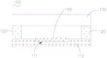
如图1所示,一种触控反馈模组100,包括悬翼板110、传递结构120、触摸板130及压电马达140,其中,悬翼板110上设有容纳部111,容纳部111设置在悬翼板110的内部,或是容纳部111设置在悬翼板110相对的两个表面中任一个上,多个容纳部111可以有部分设置在一表面上,另一部分设置在另一表面上,容纳部111的数目和形状与压电马达140一致;压电马达140固定设置于容纳部111,压电马达140的面积小于容纳部111的面积,或是压电马达140的面积等于容纳部111的面积;沿垂直于压电马达140和悬翼板110的层叠方向,至少部分压电马达140的投影与悬翼板110的投影相交叠,使得部分压电马达140设置在悬翼板110的内部,或是全部压电马达140设置在悬翼板110 的内部;传递结构120设置于悬翼板110,触摸板130架设于传递结构120远离悬翼板110的一侧。As shown in FIG. 1 , a
在具体设置时,悬翼板110可以采用铝合金、电木、玻璃、不锈钢、其他合金材料等,较佳地,悬翼板110选用具有轻质和高强度特点的铝合金,在保证在同样的悬翼板110的机械强度的基础上能够减轻整体构造的厚度,而悬翼板110的厚度取值范围为0.3mm-5mm,例如,0.3mm、1mm、2mm、2.5mm、3mm、 3.5mm、4mm、3.5mm、5mm等,而悬翼板110的具体材质和厚度根据触控反馈模组100实际情况进行确定。In the specific setting, the
传递结构120用于传递力的作用,可以采用泡棉、橡胶、塑料等具有弹性的材料,硬度小于80A,或者传递结构120也可以采用刚性材料,并且传递结构 120与悬翼板110之间通过弹性胶相连,采用上述结构形式的传递结构120既可以保证良好的传递效果,又可以消除悬翼板110变形带来的影响。The
压电马达140可以采用有机压电材料、无机陶瓷压电材料、单晶压电材料、无铅压电材料等,通过沉积、粘接、卡扣连接、凹凸配合连接等方式设置于悬翼板110的容纳部111内部,较佳地,压电马达140选用压电陶瓷,当压电陶瓷为长方体状时,长宽高尺寸可以是50mm*10mm*0.2mm,此时容纳部111的形状是与该压电陶瓷相匹配的长方体容纳部,当然,压电马达140还可以是正方体状、圆柱状、环形状等。The
触摸板130通过两组传递结构120架设于悬翼板110上方,触摸板130与压电马达140之间具有一定的间距,该间距用于限制触摸板130的振动,并且大于触摸板130向下振动的振幅,以防止压伤压电马达140。The
上述触控反馈模组100中,由于触摸板130向下振动的振幅由压电马达140 和触摸板130之间的距离所限制,通在悬翼板110上设置容纳部111,压电马达 140设置在容纳部111内,并限定沿垂直于压电马达140和悬翼板110的层叠方向,至少部分压电马达140的投影与悬翼板110的投影相交叠,使得至少部分压电马达140设置在悬翼板110的内部;相对于现有技术中的触控反馈模组,保证压电马达140和触摸板130之间的距离不变,上述触控反馈模组100中的传递结构120的厚度有明显的减小,因此,上述触控反馈模组100在保证触摸板130同样向下振动振幅的情况下能够减小传递结构120的厚度,进而能够降低触控反馈模组100的整体厚度,有利于实现轻薄化。In the above
容纳部111的设置方式具有多种,如图1、图2、图3、图4、图5以及图6 所示,一种优选实施方式,容纳部111开口于悬翼板110朝向触摸板130的表面,并且沿着悬翼板110朝向触摸板130的表面的方向向着悬翼板110的内部延伸一定的深度形成凹陷,而延伸深度的大小根据压电马达140特性、具体应用场景以及悬翼板110的实际情况进行确定。There are various ways of setting the
上述触控反馈模组100中,通过将压电马达140设置在容纳部111内,以使得在保证触摸板130同样向下振动振幅的情况下,传递结构120的厚度较小,进而能够降低触控反馈模组100的整体厚度;而由于容纳部111设置在悬翼板110朝向触摸板130的一侧,而悬翼板110背离触摸板130的表面没有受到影响仍为完整的平面,此时,悬翼板110能够适用于各种支撑结构,以避免容纳部 111的设置对悬翼板110的支撑结构造成影响,如图4所示,悬翼板110的支撑结构为悬翼板110背离压电马达140的一侧具有的凸出部112,凸出部112用于支撑整体构造,为悬翼板110提供振动的支点,采用胶水粘接、螺纹锁紧、凹凸卡扣的方式组装于主机外壳中;当然,支撑结构并不局限于上述突出部112,如图5所示,支撑结构还可以为支撑板150,支撑板150抵接在悬翼板110背离触摸板130的表面,用于支撑悬翼板110;如图6所示,支撑结构还可以为锁紧孔113,锁紧孔113设置在悬翼板110背离触摸板130的一侧,用于将悬翼板 110组装在主体外壳上,以支撑悬翼板110。In the above
容纳部111的深度具有多种情况,如图1、图2以及图3所示,一种优选实施方式,容纳部111的深度不大于悬翼板110厚度的三分之二,在具体设置时,容纳部的111的深度可以为悬翼板110厚度的三分之二,容纳部的111的深度还可以小于悬翼板110厚度的三分之二,如容纳部111的深度可以为悬翼板110 厚度的十二分之七、二分之一、十二分之五、三分之一、四分之一、六分之一、十二分之一等,而容纳部的111的深度与悬翼板110厚度的关系根据压电马达 140特性、具体应用场景以及悬翼板110的实际情况进行确定。The depth of the
上述触控反馈模组100中,通过设定容纳部111的深度不大于悬翼板110 厚度的三分之二,以限定悬翼板110最小厚度处的厚度不小于其它位置处悬翼板厚度的三分之一,以保证悬翼板110整体的结构强度并不因容纳部111的设置而有较大的影响,从而保证悬翼板110对压电马达140的支撑强度,进而能够保证触控反馈模组100的可靠性,提高产品的稳定性和使用寿命。In the above
如图3所示,容纳部的111的深度为悬翼板110厚度的十二分之五,在将压电马达140设置在容纳部111内时压电马达140朝向触摸板130的表面超出容纳部111,此时,悬翼板110整体的结构强度较大,对压电马达140的支撑强度较大,能够更好地支撑压电马达140,在保证触摸板130同样向下振动振幅的情况下传递结构120的厚度较小,触控反馈模组100的整体厚度较小,可靠性更强。As shown in FIG. 3 , the depth of the
在上述触控反馈模组100的基础上,为了进一步降低触控反馈模组100的整体厚度,如图1以及图2所示,具体地,容纳部111的深度不小于压电马达 140的厚度,在具体设置时,容纳部111的深度可以等于压电马达140的厚度,容纳部111的深度也可以大于压电马达140的厚度;上述触控反馈模组100,通过限定容纳部111的深度不小于压电马达140的厚度,以进一步减小传递结构 120的厚度,从而能够降低触控反馈模组100的整体厚度。On the basis of the above
如图1所示,容纳部111的深度与压电马达140的厚度大致相等,在将压电马达140设置在容纳部111内时悬翼板110朝向触摸板130的表面与压电马达140朝向触摸板130的表面相平齐,此时,在保证触摸板130同样向下振动振幅的情况下传递结构120的厚度较小,而且悬翼板110整体的结构强度较大,能够较好地支撑压电马达140,触控反馈模组100的整体厚度较小,可靠性较强。As shown in FIG. 1 , the depth of the
如图2所示,容纳部的111的深度为悬翼板110厚度的三分之二,在将压电马达140设置在容纳部111内时压电马达140朝向触摸板130的表面位于容纳部111内部,此时,在保证触摸板130同样向下振动振幅的情况下传递结构 120的厚度进一步减小,在传递结构120能够满足传递需要的基础上,传递结构 120的厚度可以减小至触摸板130向下振动到最大幅度时恰好与压电马达140朝向触摸板130的表面相接触,以使得触控反馈模组100的整体厚度更小,而且悬翼板110整体的结构强度能够满足对压电马达140的支撑要求,触控反馈模组100的整体厚度更小,可靠性较强。As shown in FIG. 2 , the depth of the
容纳部111的设置方式具有多种,如图7、图8、图9、图10以及图11所示,一种优选实施方式,容纳部111开口于悬翼板110背离触摸板130的表面,并且沿着悬翼板110背离触摸板130的表面的方向向着悬翼板110的内部延伸一定的深度形成凹陷,而延伸深度的大小根据压电马达140特性、具体应用场景以及悬翼板110的实际情况进行确定。The
上述触控反馈模组100中,通过将压电马达140设置在容纳部111内,以使得在保证触摸板130同样向下振动振幅的情况下,传递结构120的厚度能够进一步减小,在传递结构120能够满足传递需要的基础上,传递结构120的厚度可以减小至触摸板130向下振动到最大幅度时恰好与悬翼板110的表面相接触,以使得触控反馈模组100的整体厚度更小,进而能够降低触控反馈模组100 的整体厚度;而由于容纳部111设置在悬翼板110背离触摸板130的一侧,而悬翼板110朝向触摸板130的表面没有受到影响仍为完整的平面,能够便于传递结构120设置在悬翼板110上。In the above
而由于容纳部111设置在悬翼板110背离触摸板130的一侧,支撑方式与容纳部111设置在悬翼板110朝向触摸板130的一侧时的支撑方式相比有所不同。此时的支撑结构也具有多种,如图10所示,具体地,悬翼板110上设有锁紧孔113,锁紧孔113开口于悬翼板110背离触摸板130的表面,并且沿垂直于悬翼板110背离触摸板130的表面的方向向着悬翼板110的内部延伸一定深度,具体的深度大小根据触控反馈模组100的实际情况进行确定。However, since the
上述触控反馈模组100中,通过锁紧孔113能够将悬翼板110固定在主体壳体上,并且实现悬翼板110的支撑,锁紧孔113实现支撑安装结构简单且安装较为方便快捷;当然,支撑结构并不局限于锁紧孔113,还可以为其它结构形式,如图11所示,支撑结构还可以为支撑板150,支撑板150设置在悬翼板110 背离触摸板130的一侧,并且抵接于压电马达140背离触摸板130的表面,用于支撑悬翼板110,而为了保护压电马达140,支撑板150和压电马达140之间还可设置弹性保护层。In the above-mentioned
容纳部111的深度具有多种情况,如图7、图8以及图9所示,一种优选实施方式,容纳部111的深度不大于悬翼板110厚度的三分之二,在具体设置时,容纳部的111的深度可以为悬翼板110厚度的三分之二,容纳部的111的深度还可以小于悬翼板110厚度的三分之二,如容纳部111的深度可以为悬翼板110 厚度的十二分之七、二分之一、十二分之五、三分之一、四分之一、六分之一、十二分之一等,而容纳部的111的深度与悬翼板110厚度的关系根据压电马达 140特性、具体应用场景以及悬翼板110的实际情况进行确定。The depth of the
上述触控反馈模组100中,通过设定容纳部111的深度不大于悬翼板110 厚度的三分之二,以限定悬翼板110最小厚度处的厚度不小于其它位置处悬翼板厚度的三分之一,以保证悬翼板110整体的结构强度并不因容纳部111的设置而有较大的影响,从而保证悬翼板110对压电马达140的支撑强度,进而能够保证触控反馈模组100的可靠性,提高产品的稳定性和使用寿命。In the above
如图9所示,容纳部的111的深度为悬翼板110厚度的十二分之五,在将压电马达140设置在容纳部111内时压电马达140背离触摸板130的表面超出容纳部111,此时,悬翼板110整体的结构强度较大,对压电马达140的支撑强度较大,能够更好地支撑压电马达140,而由于压电马达140远离触摸板130,在保证触摸板130同样向下振动振幅的情况下传递结构120的厚度较小,同时可靠性更强。As shown in FIG. 9 , the depth of the
在上述触控反馈模组100的基础上,为了进一步降低触控反馈模组100的整体厚度,如图7以及图8所示,具体地,容纳部111的深度不小于压电马达 140的厚度,在具体设置时,容纳部111的深度可以等于压电马达140的厚度,容纳部111的深度也可以大于压电马达140的厚度;上述触控反馈模组100,通过限定容纳部111的深度不小于压电马达140的厚度,以进一步减小传递结构 120的厚度,从而能够降低触控反馈模组100的整体厚度。On the basis of the above
如图7所示,容纳部111的深度与压电马达140的厚度大致相等,在将压电马达140设置在容纳部111内时悬翼板110背离触摸板130的表面与压电马达140背离触摸板130的表面相平齐,此时,在保证触摸板130同样向下振动振幅的情况下传递结构120的厚度较小,所需支撑结构的位置不发生变化,触控反馈模组100的整体厚度较小,而且悬翼板110整体的结构强度较大,能够较好地支撑压电马达140,可靠性较强。As shown in FIG. 7 , the depth of the
如图8所示,容纳部的111的深度为悬翼板110厚度的三分之二,在将压电马达140设置在容纳部111内时压电马达140背离触摸板130的表面位于容纳部111内部,此时,在保证触摸板130同样向下振动振幅的情况下传递结构 120的厚度较小,所需支撑结构向着容纳部111移动至与压电马达140背离触摸板130的表面相接触,以减小悬翼板110背离触摸板130一侧的结构件的厚度,从而使得触控反馈模组100的整体厚度更小,而且悬翼板110整体的结构强度能够满足对压电马达140的支撑要求,可靠性较强。As shown in FIG. 8 , the depth of the
容纳部111的设置方式具有多种,如图12、图13、图14、图15、图16以及图17所示,一种优选实施方式,悬翼板110包括层叠设置的第一本体114和第二本体115,容纳部111设置在悬翼板110的内部,并且该容纳部111由第一本体114和第二本体115所围成。在具体设置时,第一本体114和第二本体115 的结构和材质可以相同,以便于加工制备以及损坏时的更换,第一本体114和第二本体115的结构和材质也可以不同,以保证不同的支撑强度;传递结构120 可以设置在第一本体114上,也可以设置在第二本体115上。值得注意的是,第一本体114和第二本体115之间可以通过粘接、卡扣连接、凹凸配合连接等方式固定位一体。There are various ways of setting the
在上述触控反馈模组100中,容纳部111位于悬翼板110的内部,压电马达140设置在容纳部111内,从而通过第一本体114和第二本体115保护压电马达140,以避免在触摸板130向下振动时对压电马达140的机械损伤,提高压电马达140的使用寿命;同时采用分体式的悬翼板110能够针对传递结构120、压电马达140的不同支撑强度改变结构特征,从而能够保证悬翼板110对传递结构120、压电马达140以及触摸板130的支撑强度,保证触控反馈模组100的可靠性。In the above-mentioned
而由于压电马达140设置在悬翼板110的内部,以使得在保证触摸板130 同样向下振动振幅的情况下,传递结构120的厚度能够进一步减小,在传递结构120能够满足传递需要的基础上,传递结构120的厚度可以减小至触摸板130 向下振动到最大幅度时恰好与悬翼板110朝向触摸板130的表面相接触,以使得触控反馈模组100的整体厚度更小,进而能够降低触控反馈模组100的整体厚度;同时悬翼板110朝向触摸板130的表面没有受到容纳部111的影响仍为完整的平面,能够便于传递结构120设置在悬翼板110上。However, since the
而悬翼板110背离触摸板130的表面没有受到容纳部111的影响仍为完整的平面,此时,悬翼板110能够适用于各种支撑结构,以避免容纳部111的设置对悬翼板110的支撑结构造成影响,如图15所示,悬翼板110的支撑结构为悬翼板110背离触摸板130的一侧具有的凸出部112,凸出部112用于支撑整体构造,为悬翼板110提供振动的支点,采用胶水粘接、螺纹锁紧、凹凸卡扣的方式组装于主机外壳中;当然,支撑结构并不局限于上述突出部112,如图16 所示,支撑结构还可以为支撑板150,支撑板150抵接在悬翼板110背离触摸板 130的表面,用于支撑悬翼板110;如图17所示,支撑结构还可以为锁紧孔113,锁紧孔113设置在悬翼板110背离触摸板130的一侧,用于将悬翼板110组装在主体外壳上,以支撑悬翼板110。The surface of the
容纳部111在悬翼板110内部的设置方式具有多种,如图12、图13所示,具体地,容纳部111设置在第一本体114,并且该容纳部111开口于第一本体 114朝向第二本体115的表面,并沿垂直于第一本体114朝向第二本体115的表面的方向向着第一本体114的内部延伸一定的深度形成凹陷,该深度可以与压电马达140的厚度相同,以降低整个悬翼板110的厚度,该深度也可以大于压电马达140的厚度,以便于压电马达140的安装,此时第二本体115朝向第一本体114的表面可以为平面,也可以为T型面,该T型面凸出的部分可以嵌入到容纳部111内;而容纳部111延伸深度的大小根据压电马达140特性、具体应用场景以及悬翼板110的实际情况进行确定。The
上述触控反馈模组100中,将容纳部111整体设置在第一本体114上,一方面便于容纳部111的设置,加工较为方便,另一方面也便于压电马达140的安装;在具体设置时,如图12所示,第二本体115靠近触摸板130,传递结构 120设置在第二本体115朝向触摸板130的表面,此时,第二本体115可以选择支撑强度较高的材质,以便于支撑传递结构120以及触摸板130;如图13所示,第一本体114靠近触摸板130,传递结构120设置在第一本体114朝向触摸板 130的表面,此时,第一本体114可以选择高强度的材质,以便于第一本体114 在设置容纳部111后仍能够较好地支撑传递结构120以及触摸板130。In the above
容纳部111在悬翼板110内部的设置方式具有多种,如图14所示,具体地,容纳部111包括相对设置的第一容纳部116和第二容纳部117,第一容纳部116 开口于第一本体114朝向第二本体115的表面,并沿垂直于第一本体114朝向第二本体115的表面的方向向着第一本体114的内部延伸一定的深度形成凹陷,第二容纳部117开口于第二本体115朝向第一本体114的表面,并沿垂直于第二本体115朝向第一本体114的表面的方向向着第二本体115的内部延伸一定的深度形成凹陷,在具体设置时,第一容纳部116和第二容纳部117的深度可以相同,以便于加工制备,第一容纳部116和第二容纳部117的深度也可以不同,以便于第一本体114和第二本体115提供不同的支撑强度,如第一本体114 支撑传递结构120以及触摸板130,第二本体115支撑压电马达140;第一容纳部116和第二容纳部117的深度之和可以与压电马达140的厚度相同,以降低整个悬翼板110的厚度,第一容纳部116和第二容纳部117的深度之和也可以大于压电马达140的厚度,以便于压电马达140的安装。The
在上述触控反馈模组100中,将容纳部111的深度分散到第一本体114和第二本体115上,以使得第一本体114和第二本体115的结构强度较高,从而能够保证悬翼板110对传递结构120、压电马达140以及触摸板130的支撑强度,而且同时能够保证第一本体114和第二本体115结构稳定性,提高悬翼板1110 的支撑强度以及可靠性,进而提高整个触控反馈模组100的稳定性和使用寿命。In the above-mentioned
由于容纳部111的存在影响悬翼板对压电马达的支撑强度,为了提高整体模组的可靠性,如图18所示,一种优选实施方式,容纳部111的底部设有补强板160,压电马达140设置于补强板160,通过补强板160提高对压电马达140 的支撑作用,以保证悬翼板对压电马达140的支撑强度,从而保护压电马达140,进而保证触控反馈模组的可靠性。Since the existence of the
上述触控反馈模组100中,在具体设置时,压电马达140可以先贴合该补强板160,再与悬翼板110的容纳部111组合;如图18所示,补强板160可以设置在第一容纳部116和第二容纳部117内,也可以设置在只设置在第二容纳部117内;而补强板160并不局限于如图18所示的触控反馈模组100,还可以为其他触控反馈模组100,此时,补强板160位于容纳部111的底部和压电马达 140之间;补强板160的材料可以为钢板、合金板或是其他支撑强度较大的材料,而且容纳部111的底部还可以设置其他保护层,如防水材料、柔性电路板等;容纳部111的底部的具体保护层的结构以及具体材料根据触控反馈模组100的实际情况进行确定。In the above-mentioned
值得注意的是,上述触控反馈模组100中,为了提高压力感知的一致性和触控反馈的均匀性,悬翼板110、传递结构120、触摸板130、压电马达140、缓冲组件150、容纳部111、凸出部112、锁紧孔113以及补强板160均悬翼板 110的中心线X构呈对称结构分布,此时,按压触摸板130不同的位置,压电马达140输出的电压信号波动范围较小,压力感知一致性较高,压电马达140接收电压信号,触摸板130能够产生均匀的沿层叠方向的位移,触控反馈的均匀性较好。It is worth noting that in the above
另外,本实用新型还提供一种触控装置,包括如上任一实施例的触控反馈模组100。触控装置包括但不限于笔记本电脑、手机、车载设备等需要触控反馈和压力感知的装置。例如,如果触控装置为笔记本电脑,则触控反馈模组100 为笔记本电脑的输入触控反馈模组,也称为PC触控反馈模组。In addition, the present invention also provides a touch device, including the
上述触控装置,由于触控反馈模组100通过在悬翼板110上设置容纳部111,并将压电马达140设置在容纳部111内,在保证触摸板130同样向下振动振幅的情况下能够减小传递结构120的厚度,进而能够降低触控反馈模组100的整体厚度,因此,具有该触控反馈模组100的触控装置的整体厚度较小,能够实现触控装置的轻薄化。In the above-mentioned touch device, since the
以上所述实施例的各技术特征可以进行任意的组合,为使描述简洁,未对上述实施例中的各个技术特征所有可能的组合都进行描述,然而,只要这些技术特征的组合不存在矛盾,都应当认为是本说明书记载的范围。The technical features of the above-described embodiments can be combined arbitrarily. For the sake of brevity, all possible combinations of the technical features in the above-described embodiments are not described. However, as long as there is no contradiction between the combinations of these technical features, All should be regarded as the scope described in this specification.
以上所述实施例仅表达了本实用新型的几种实施方式,其描述较为具体和详细,但并不能因此而理解为对实用新型专利范围的限制。应当指出的是,对于本领域的普通技术人员来说,在不脱离本实用新型构思的前提下,还可以做出若干变形和改进,这些都属于本实用新型的保护范围。因此,本实用新型专利的保护范围应以所附权利要求为准。The above-mentioned embodiments only represent several embodiments of the present utility model, and the descriptions thereof are specific and detailed, but should not be construed as a limitation on the scope of the utility model patent. It should be pointed out that for those of ordinary skill in the art, some modifications and improvements can be made without departing from the concept of the present invention, which all belong to the protection scope of the present invention. Therefore, the protection scope of the patent for this utility model shall be subject to the appended claims.
Claims (11)
Applications Claiming Priority (2)
| Application Number | Priority Date | Filing Date | Title |
|---|---|---|---|
| CN2019108039360 | 2019-08-28 | ||
| CN201910803936 | 2019-08-28 |
Publications (1)
| Publication Number | Publication Date |
|---|---|
| CN211236846U true CN211236846U (en) | 2020-08-11 |
Family
ID=71046014
Family Applications (7)
| Application Number | Title | Priority Date | Filing Date |
|---|---|---|---|
| CN201911175848.7A Pending CN112445331A (en) | 2019-08-28 | 2019-11-26 | Touch feedback module and touch device |
| CN201922071417.8U Expired - Fee Related CN211375552U (en) | 2019-08-28 | 2019-11-26 | Touch feedback module and touch device |
| CN201911175819.0A Pending CN112445329A (en) | 2019-08-28 | 2019-11-26 | Touch feedback module and touch device |
| CN201922070190.5U Expired - Fee Related CN211236846U (en) | 2019-08-28 | 2019-11-26 | Touch feedback module and touch device |
| CN201922073455.7U Expired - Fee Related CN210776588U (en) | 2019-08-28 | 2019-11-26 | Touch feedback module and touch device |
| CN201911175846.8A Pending CN112445330A (en) | 2019-08-28 | 2019-11-26 | Touch feedback module and touch device |
| CN201922071452.XU Expired - Fee Related CN210776587U (en) | 2019-08-28 | 2019-11-26 | Touch feedback module and touch device |
Family Applications Before (3)
| Application Number | Title | Priority Date | Filing Date |
|---|---|---|---|
| CN201911175848.7A Pending CN112445331A (en) | 2019-08-28 | 2019-11-26 | Touch feedback module and touch device |
| CN201922071417.8U Expired - Fee Related CN211375552U (en) | 2019-08-28 | 2019-11-26 | Touch feedback module and touch device |
| CN201911175819.0A Pending CN112445329A (en) | 2019-08-28 | 2019-11-26 | Touch feedback module and touch device |
Family Applications After (3)
| Application Number | Title | Priority Date | Filing Date |
|---|---|---|---|
| CN201922073455.7U Expired - Fee Related CN210776588U (en) | 2019-08-28 | 2019-11-26 | Touch feedback module and touch device |
| CN201911175846.8A Pending CN112445330A (en) | 2019-08-28 | 2019-11-26 | Touch feedback module and touch device |
| CN201922071452.XU Expired - Fee Related CN210776587U (en) | 2019-08-28 | 2019-11-26 | Touch feedback module and touch device |
Country Status (2)
| Country | Link |
|---|---|
| CN (7) | CN112445331A (en) |
| WO (4) | WO2021036053A1 (en) |
Families Citing this family (10)
| Publication number | Priority date | Publication date | Assignee | Title |
|---|---|---|---|---|
| CN112558780A (en) * | 2020-12-23 | 2021-03-26 | 江西欧迈斯微电子有限公司 | Touch feedback module and electronic equipment |
| TW202243295A (en) * | 2021-04-22 | 2022-11-01 | 達運精密工業股份有限公司 | Vibration module and method for manufacturing the same |
| CN113983940B (en) * | 2021-08-06 | 2024-12-27 | 西安理工大学 | Device and method for detecting thermally induced micro strain of energy storage batteries using F-P/FBG multiplexing technology |
| CN113900547A (en) * | 2021-09-06 | 2022-01-07 | 歌尔光学科技有限公司 | Ultrasonic wave and piezoelectric touch device and intelligent terminal |
| CN113867552A (en) * | 2021-10-20 | 2021-12-31 | 广东虹勤通讯技术有限公司 | Global pressing computer touch pad |
| CN114237410A (en) * | 2021-12-30 | 2022-03-25 | 深圳莱宝高科技股份有限公司 | Touch control panel and electronic equipment |
| CN115729355A (en) * | 2022-12-03 | 2023-03-03 | 常州慧眼通讯科技有限公司 | Touch pad with high vibration feedback degree |
| CN119546165A (en) * | 2023-08-29 | 2025-02-28 | 北京小米移动软件有限公司 | Piezoelectric module and electronic equipment |
| CN117331444B (en) * | 2023-10-13 | 2024-07-30 | 深圳市亚米拉电子科技有限公司 | Novel pressure sensing structure with pressure sensing feedback function and pressure sensing method |
| TWI866756B (en) * | 2024-01-24 | 2024-12-11 | 久正光電股份有限公司 | Haptic feedback device |
Family Cites Families (19)
| Publication number | Priority date | Publication date | Assignee | Title |
|---|---|---|---|---|
| KR101146530B1 (en) * | 2005-08-30 | 2012-05-25 | 삼성전자주식회사 | Touch panel having a function of speaker |
| CN101206548B (en) * | 2006-12-19 | 2012-01-11 | 北京汇冠新技术股份有限公司 | Infrared touch panel triggered using touch force and detecting method thereof |
| US8633916B2 (en) * | 2009-12-10 | 2014-01-21 | Apple, Inc. | Touch pad with force sensors and actuator feedback |
| KR101080641B1 (en) * | 2010-06-30 | 2011-11-08 | 주식회사 하이소닉 | Handheld terminal with haptic module |
| CN203054722U (en) * | 2012-12-13 | 2013-07-10 | 中航华东光电有限公司 | Three-dimensional vibration feedback device and displayer |
| US10578499B2 (en) * | 2013-02-17 | 2020-03-03 | Microsoft Technology Licensing, Llc | Piezo-actuated virtual buttons for touch surfaces |
| CN203840397U (en) * | 2014-04-11 | 2014-09-17 | 瑞声声学科技(深圳)有限公司 | Piezoelectric module and electronic equipment using the piezoelectric module |
| CN205959176U (en) * | 2016-06-17 | 2017-02-15 | 深圳纽迪瑞科技开发有限公司 | Touch piece is with pressure sensing structure and touch devices |
| CN107515688B (en) * | 2016-06-17 | 2024-04-19 | 深圳纽迪瑞科技开发有限公司 | Pressure sensing structure for touch piece and touch device |
| CN206181544U (en) * | 2016-10-12 | 2017-05-17 | 深圳市柔宇科技有限公司 | Touch -control structure |
| CN206532267U (en) * | 2017-03-10 | 2017-09-29 | 信利光电股份有限公司 | A kind of electronic equipment and its vibration Trackpad |
| KR102384033B1 (en) * | 2017-03-20 | 2022-04-06 | 엘지전자 주식회사 | Display Apparatus |
| US10678364B2 (en) * | 2017-03-23 | 2020-06-09 | Immersion Corporation | System for providing sensor and actuation functionality for touch input device |
| US10622538B2 (en) * | 2017-07-18 | 2020-04-14 | Apple Inc. | Techniques for providing a haptic output and sensing a haptic input using a piezoelectric body |
| KR102363707B1 (en) * | 2017-08-03 | 2022-02-17 | 삼성전자주식회사 | An electronic apparatus comprising a force sensor and a method for controlling electronic apparatus thereof |
| FI128874B (en) * | 2017-10-03 | 2021-02-15 | Aito Bv | Piezo haptic feedback device with integrated support |
| US10545581B2 (en) * | 2017-10-05 | 2020-01-28 | Advanced Semiconductor Engineering, Inc. | Semiconductor package device |
| US10345910B1 (en) * | 2018-06-15 | 2019-07-09 | Immersion Corporation | Haptic actuator assembly with a spring pre-load device |
| CN108762582A (en) * | 2018-07-27 | 2018-11-06 | 北京小米移动软件有限公司 | Touch control component and electronic equipment |
-
2019
- 2019-11-26 WO PCT/CN2019/121066 patent/WO2021036053A1/en not_active Ceased
- 2019-11-26 CN CN201911175848.7A patent/CN112445331A/en active Pending
- 2019-11-26 CN CN201922071417.8U patent/CN211375552U/en not_active Expired - Fee Related
- 2019-11-26 WO PCT/CN2019/121022 patent/WO2021036051A1/en not_active Ceased
- 2019-11-26 WO PCT/CN2019/121070 patent/WO2021036054A1/en not_active Ceased
- 2019-11-26 WO PCT/CN2019/121055 patent/WO2021036052A1/en not_active Ceased
- 2019-11-26 CN CN201911175819.0A patent/CN112445329A/en active Pending
- 2019-11-26 CN CN201922070190.5U patent/CN211236846U/en not_active Expired - Fee Related
- 2019-11-26 CN CN201922073455.7U patent/CN210776588U/en not_active Expired - Fee Related
- 2019-11-26 CN CN201911175846.8A patent/CN112445330A/en active Pending
- 2019-11-26 CN CN201922071452.XU patent/CN210776587U/en not_active Expired - Fee Related
Also Published As
| Publication number | Publication date |
|---|---|
| WO2021036053A1 (en) | 2021-03-04 |
| CN210776587U (en) | 2020-06-16 |
| CN211375552U (en) | 2020-08-28 |
| WO2021036054A1 (en) | 2021-03-04 |
| WO2021036052A1 (en) | 2021-03-04 |
| CN112445331A (en) | 2021-03-05 |
| CN210776588U (en) | 2020-06-16 |
| CN112445330A (en) | 2021-03-05 |
| CN112445329A (en) | 2021-03-05 |
| WO2021036051A1 (en) | 2021-03-04 |
Similar Documents
| Publication | Publication Date | Title |
|---|---|---|
| CN211236846U (en) | Touch feedback module and touch device | |
| US9431926B2 (en) | Vibration generating apparatus and electronic apparatus including the same | |
| CN102905485B (en) | Impact-resistant electronic device | |
| US20110095649A1 (en) | Vibrating device | |
| CN112865468B (en) | Linear vibration motor | |
| US20170105073A1 (en) | Sound generator | |
| CN104081793A (en) | Suspension member with integrated sealing member | |
| CN211719617U (en) | Piezoelectric module, touch feedback module and touch device | |
| US9515248B2 (en) | Vibration generating apparatus | |
| CN211604073U (en) | Touch feedback module and touch device | |
| CN114546167A (en) | Trackpads and Electronics | |
| WO2012144571A1 (en) | Piezoelectric actuator and electronic device having piezoelectric actuator mounted thereon | |
| CN110515500B (en) | Force sensor and display device | |
| CN201749419U (en) | Touch vibration feedback system with two ends fixed | |
| CN211718865U (en) | Touch feedback module and electronic equipment | |
| CN206271777U (en) | A battery fixing device and mobile terminal | |
| CN112068702B (en) | A vibration device | |
| CN119032334A (en) | Haptic feedback module and electronic device | |
| KR20240107621A (en) | Apparatus | |
| CN210402269U (en) | Vibration feedback structure of touch pad and electronic equipment | |
| CN201717836U (en) | Piezoelectric vibrator and electronic element | |
| CN209417633U (en) | Display screen supporting structure and supporting pad | |
| CN114428567A (en) | Touch control panel and terminal equipment | |
| CN217063680U (en) | Clock oscillator, chip, electronic equipment and device | |
| CN208299777U (en) | Press-key structure is isolated in metal based on piezoelectric ceramics |
Legal Events
| Date | Code | Title | Description |
|---|---|---|---|
| GR01 | Patent grant | ||
| GR01 | Patent grant | ||
| CP03 | Change of name, title or address |
Address after: 330096 No.699 Tianxiang North Avenue, Nanchang hi tech Industrial Development Zone, Nanchang City, Jiangxi Province Patentee after: Jiangxi OMS Microelectronics Co.,Ltd. Address before: 330000 east of Xueyuan 6th Road, south of Tianxiang Avenue, Nanchang hi tech Industrial Development Zone, Nanchang City, Jiangxi Province Patentee before: OFilm Microelectronics Technology Co.,Ltd. Address after: 330000 east of Xueyuan 6th Road, south of Tianxiang Avenue, Nanchang hi tech Industrial Development Zone, Nanchang City, Jiangxi Province Patentee after: OFilm Microelectronics Technology Co.,Ltd. Address before: 330029 No. 1189 Jingdong Avenue, Nanchang high tech Zone, Jiangxi Patentee before: NANCHANG OFILM BIO-IDENTIFICATION TECHNOLOGY Co.,Ltd. |
|
| CP03 | Change of name, title or address | ||
| CF01 | Termination of patent right due to non-payment of annual fee |
Granted publication date: 20200811 |
|
| CF01 | Termination of patent right due to non-payment of annual fee |