CN211123468U - Fluorescent micro-lighting device adopting deep ultraviolet light source - Google Patents
Fluorescent micro-lighting device adopting deep ultraviolet light source Download PDFInfo
- Publication number
- CN211123468U CN211123468U CN201922056577.5U CN201922056577U CN211123468U CN 211123468 U CN211123468 U CN 211123468U CN 201922056577 U CN201922056577 U CN 201922056577U CN 211123468 U CN211123468 U CN 211123468U
- Authority
- CN
- China
- Prior art keywords
- light source
- deep ultraviolet
- lighting device
- fluorescence
- objective lens
- Prior art date
- Legal status (The legal status is an assumption and is not a legal conclusion. Google has not performed a legal analysis and makes no representation as to the accuracy of the status listed.)
- Active
Links
- 230000005284 excitation Effects 0.000 claims abstract description 32
- 238000005286 illumination Methods 0.000 claims abstract description 18
- VYPSYNLAJGMNEJ-UHFFFAOYSA-N Silicium dioxide Chemical compound O=[Si]=O VYPSYNLAJGMNEJ-UHFFFAOYSA-N 0.000 claims description 3
- 239000007787 solid Substances 0.000 claims description 3
- 238000001914 filtration Methods 0.000 abstract description 6
- 230000003287 optical effect Effects 0.000 abstract description 3
- 238000003384 imaging method Methods 0.000 description 5
- 238000000926 separation method Methods 0.000 description 3
- 230000000903 blocking effect Effects 0.000 description 2
- 238000000034 method Methods 0.000 description 2
- 238000013459 approach Methods 0.000 description 1
- 230000015572 biosynthetic process Effects 0.000 description 1
- 239000003795 chemical substances by application Substances 0.000 description 1
- 238000001514 detection method Methods 0.000 description 1
- 238000010586 diagram Methods 0.000 description 1
- 238000004043 dyeing Methods 0.000 description 1
- 238000005516 engineering process Methods 0.000 description 1
- 238000000799 fluorescence microscopy Methods 0.000 description 1
- 230000003760 hair shine Effects 0.000 description 1
- 239000002245 particle Substances 0.000 description 1
- 230000007170 pathology Effects 0.000 description 1
- 230000005855 radiation Effects 0.000 description 1
- 238000011160 research Methods 0.000 description 1
- 238000010186 staining Methods 0.000 description 1
- 230000000638 stimulation Effects 0.000 description 1
- 238000012360 testing method Methods 0.000 description 1
- 238000012546 transfer Methods 0.000 description 1
Images


Landscapes
- Microscoopes, Condenser (AREA)
- Investigating, Analyzing Materials By Fluorescence Or Luminescence (AREA)
Abstract
The utility model discloses a fluorescent micro-lighting device adopting a deep ultraviolet light source. The system consists of an ocular lens, a non-transparent deep ultraviolet objective lens, a deep ultraviolet excitation light source and a light condensing system, wherein the deep ultraviolet laser light source and the light condensing system are arranged around the objective lens and form dark field illumination, the dark field illumination is irradiated on a specimen, the specimen is excited to generate fluorescence, and the fluorescence is collected by the objective lens and then imaged to the ocular lens. The utility model can use the objective lens with short working distance, thereby avoiding the light energy loss and having higher optical efficiency; the color filtering block is not needed, the structure is simple, and the cost is reduced.
Description
Technical Field
The utility model relates to a microscope technical field, in particular to fluorescence micro-excitation lighting technology.
Background
The fluorescence microscope has the advantages of high contrast, high detection capability, small stimulation to cells, capability of performing multiple staining and the like, and can be widely applied to researches of biology, hematology, histology, pathology, pharmaceutical chemistry and the like and clinical tests. The fluorescence microscope mainly comprises a fluorescence excitation source, a light condensing system, a color filtering block (consisting of an excitation color filter, a light splitting color separation block and a blocking color filter) and a microscope, generally adopts an epi-illumination structure, and has the following specific principle: the light emitted by the fluorescence excitation source after being electrified is imaged on the back focal plane of the objective lens through a light-gathering and excitation color filter (only can transmit light with a certain wavelength) and a light-splitting color-splitting sheet (the light with a wavelength smaller than the certain wavelength is reflected and the light with a wavelength larger than the certain wavelength is transmitted), and forms a Korea illumination system with the objective lens, so that uniform epi-illumination can be obtained on a sample; the sample is excited by the falling radiation to generate fluorescence, the wavelength of the fluorescence is larger than that of light which can be transmitted by the light splitting color separation sheet, and the fluorescence directly transmits through the light splitting color separation sheet and the blocking color filter (only light with a wavelength larger than a certain wavelength can be transmitted), and reaches an ocular lens or a camera device for observation.
Because the objective lens simultaneously acts as the light gathering and imaging functions, the structure is simple, and the device is widely applied. However, for specific wavelengths such as deep ultraviolet (below 350 nm), since conventional fluorescent objectives, light-gathering systems, can only transmit wavelengths above ultraviolet, this approach is not suitable unless totally redesigned, but is expensive.
The prior patent CN 107003242A discloses a system and method for controlling the imaging depth in tissue by using a fluorescence microscope under the condition of ultraviolet excitation after dyeing by using a fluorescent agent, and adopts an oblique illumination mode, i.e. illumination focusing and imaging part are independent, thus solving the problem that the objective lens can not transmit deep ultraviolet, but for a high power objective lens, because the working distance is short (such as about 1 mm), the utilization rate of oblique illumination is very low, even can not be used.
The prior patent CN 205091263U, CN105092550A discloses a fluorescence microscopic imaging method and device, which includes a light source device, a sample placing table, an objective lens, an emission and filtering module and an image acquisition device, wherein the light source device includes a plurality of monochromatic fluorescence excitation light sources and a control system electrically connected with the plurality of monochromatic fluorescence excitation light sources, the plurality of monochromatic fluorescence excitation light sources are arranged around a central axis of an imaging light path formed by the objective lens and the image acquisition device, and the monochromatic fluorescence excitation light emitted by each monochromatic fluorescence excitation light source intersects with the central axis of the imaging light path at a preset position of the sample placing table, and the control system lights at least one monochromatic fluorescence excitation light source with the same color as a target light source in the plurality of monochromatic fluorescence excitation light sources according to experimental requirements; the sample placing table is arranged at the intersection position of the monochromatic fluorescence excitation light emitted by the plurality of monochromatic fluorescence excitation light sources. However, the comparison document is used for transmitting fluorescence, and needs a color filtering block, so that the cost is higher.
Disclosure of Invention
The utility model provides a fluorescent micro-lighting device adopting a deep ultraviolet light source. The technical scheme of the utility model be, install deep ultraviolet excitation light source and condensing system around objective, the light that the excitation light source sent forms dark field illumination behind condensing system and shines on the sample face, excites the sample to send fluorescence, collects the back through objective and on the formation of image to the eyepiece.
The fluorescence excitation light source is an ultraviolet solid-state light source with the wavelength less than 400nm, such as L ED, and solid-state laser, preferably L ED, &lTtT transfer = L "&gTt L &/T &gTt ED is fixed on the annular circuit board.
The ultraviolet solid-state light source is L ED.
The number of the fluorescence excitation light sources may be one or more.
The wavelength may be a single wavelength or a combination of wavelengths.
The light condensing system is any one or combination of a lens, an off-axis paraboloid and an off-axis curved surface.
The light condensing system is used for forming dark field illumination by light emitted by the excitation light source and converging the dark field illumination on the specimen plane to be superposed with the focal plane of the objective lens.
The lens must be transparent to deep ultraviolet light, such as quartz glass.
The fluorescence microscope in the prior art patent uses filter blocks, the wavelength of the fluorescence microscope is changed by the filter blocks, and each emission filter area has a passing waveband which is a waveband of fluorescence emitted by particles in a sample plate excited by a monochromatic fluorescence excitation light source of one color. The invention can change the wavelength through the fluorescence excitation light source without using a color filtering block, thereby achieving the purpose of exciting the fluorescence of the sample. Therefore, the utility model has the advantages that: the objective lens with short working distance can be used, so that the optical energy loss is avoided, and the optical efficiency is higher; the color filtering block is not needed, the structure is simple, and the cost is reduced.
Drawings
The accompanying drawings, which are described herein, serve to provide a further understanding of the invention and constitute a part of this specification, and the exemplary embodiments and descriptions thereof are provided for explaining the invention without unduly limiting it. In the drawings:
fig. 1 is a schematic view of a single curved reflector of the present invention.
Figure 2 shows the utility model discloses a see through dark ultraviolet sketch map.
Figure 3 shows the utility model discloses a patent microscope passes through dark ultraviolet sketch map.
Figure 4 shows the utility model discloses a see through dark ultraviolet structure schematic diagram.
Detailed Description
To further illustrate the embodiments, the present invention provides the accompanying drawings. The accompanying drawings, which are incorporated in and constitute a part of this disclosure, illustrate embodiments of the invention and, together with the description, serve to explain the principles of the embodiments. Those skilled in the art will appreciate still other possible embodiments and advantages of the present invention with reference to these figures. Elements in the figures are not drawn to scale and like reference numerals are generally used to indicate like elements.
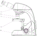
As shown in fig. 1, 2, 3, and 4, the present invention provides a fluorescence micro-lighting device using deep ultraviolet light source, which comprises a specimen 1, a specimen 2, an off-axis paraboloid 3, a light source 4, an objective lens 5, an eyepiece 6, a lens array 7, a head 8, a dark field objective lens 9, a stage 10, a frame 11, an objective lens liner 12, a wire buckle 13, and a housing, wherein the deep ultraviolet excitation light source 3 is a solid state light source such as L ED, a solid state laser, preferably L ED, and the light source 3 is fixed on a circular circuit board, the number of the light source 3 can be single or multiple, and the wavelength can be single wavelength or multiple wavelength combination.
The deep ultraviolet excitation light source 3 and the condensing system thereof are arranged around the objective lens, light emitted by the excitation light source 3 forms a dark field illumination after passing through the condensing system and irradiates the surface of the specimen 1, the specimen 1 is excited to emit fluorescence, and the fluorescence is collected by the objective lens 4 and then imaged on the ocular lens 5. The light-gathering system is any one or combination of a lens array 6, an off-axis paraboloid 2 and an off-axis curved surface.
The light condensing system is used for forming dark field illumination by the light emitted by the excitation light source 3 and converging the dark field illumination on the surface of the specimen 1, and the dark field illumination is superposed with the focal plane of the objective 4. The light-gathering system can be composed of a ring lens, a lens array 6 and a curved reflector, as shown in fig. 1, a single curved reflector such as an off-axis parabolic reflector can be used, and the lens can transmit deep ultraviolet rays such as quartz glass.
While the invention has been particularly shown and described with reference to a preferred embodiment, it will be understood by those skilled in the art that various changes in form and detail may be made therein without departing from the spirit and scope of the invention as defined by the appended claims.
Claims (9)
1. The utility model provides an adopt fluorescence micro-lighting device of deep ultraviolet light source, comprises eyepiece, objective, fluorescence excitation light source and condensing system, its characterized in that: the fluorescence excitation light source and the light condensing system are arranged around the objective lens, light emitted by the excitation light source forms dark field illumination through the light condensing system and irradiates on the specimen, the specimen is excited to emit fluorescence, and the fluorescence is collected by the objective lens and then imaged on the eyepiece.
2. The fluorescent micro-lighting device using deep ultraviolet light source as claimed in claim 1, wherein: the fluorescence excitation light source is an ultraviolet solid-state light source, and the wavelength of the ultraviolet solid-state light source is less than 400 nm.
3. The fluorescent micro-lighting device using deep ultraviolet light source as claimed in claim 2, wherein: the wavelength is a single wavelength or a combination of multiple wavelengths.
4. The fluorescent micro-lighting device using deep ultraviolet light source as claimed in claim 2, wherein said ultraviolet solid state light source is deep ultraviolet L ED.
5. The fluorescent micro-lighting device using deep ultraviolet light source as claimed in claim 1, wherein: the fluorescence excitation light source is one or more than one.
6. The fluorescent micro-lighting device using deep ultraviolet light source as claimed in claim 1, wherein: the light-gathering system is any one or combination of a lens, an off-axis paraboloid and an off-axis curved surface.
7. The fluorescent micro-lighting device using deep ultraviolet light source as claimed in claim 1, wherein: the light condensing system is used for forming dark field illumination by light emitted by the excitation light source and converging the dark field illumination on the specimen plane to be superposed with the focal plane of the objective lens.
8. The fluorescent micro-lighting device using deep ultraviolet light source as claimed in claim 1, wherein: the lens of the condensing system must be transparent to deep ultraviolet.
9. The fluorescent micro-lighting device using deep ultraviolet light source as claimed in claim 8, wherein: the lens is made of quartz glass.
Priority Applications (1)
| Application Number | Priority Date | Filing Date | Title |
|---|---|---|---|
| CN201922056577.5U CN211123468U (en) | 2019-11-26 | 2019-11-26 | Fluorescent micro-lighting device adopting deep ultraviolet light source |
Applications Claiming Priority (1)
| Application Number | Priority Date | Filing Date | Title |
|---|---|---|---|
| CN201922056577.5U CN211123468U (en) | 2019-11-26 | 2019-11-26 | Fluorescent micro-lighting device adopting deep ultraviolet light source |
Publications (1)
| Publication Number | Publication Date |
|---|---|
| CN211123468U true CN211123468U (en) | 2020-07-28 |
Family
ID=71701412
Family Applications (1)
| Application Number | Title | Priority Date | Filing Date |
|---|---|---|---|
| CN201922056577.5U Active CN211123468U (en) | 2019-11-26 | 2019-11-26 | Fluorescent micro-lighting device adopting deep ultraviolet light source |
Country Status (1)
| Country | Link |
|---|---|
| CN (1) | CN211123468U (en) |
Cited By (1)
| Publication number | Priority date | Publication date | Assignee | Title |
|---|---|---|---|---|
| CN110888228A (en) * | 2019-11-26 | 2020-03-17 | 麦克奥迪实业集团有限公司 | Fluorescent microscopic illumination method adopting deep ultraviolet light source |
-
2019
- 2019-11-26 CN CN201922056577.5U patent/CN211123468U/en active Active
Cited By (1)
| Publication number | Priority date | Publication date | Assignee | Title |
|---|---|---|---|---|
| CN110888228A (en) * | 2019-11-26 | 2020-03-17 | 麦克奥迪实业集团有限公司 | Fluorescent microscopic illumination method adopting deep ultraviolet light source |
Similar Documents
| Publication | Publication Date | Title |
|---|---|---|
| EP2183636B1 (en) | Light emitting diode illumination system | |
| RU2182328C2 (en) | Fluorescent microscope | |
| US10649186B2 (en) | Mobile microscope | |
| CN105092550A (en) | Fluorescent microscopic imaging method and device | |
| US20240402477A1 (en) | Multiscale lens systems and methods for imaging well plates and including event-based detection | |
| US10634890B1 (en) | Miniaturized microscope for phase contrast and multicolor fluorescence imaging | |
| CN108780216B (en) | Imaging systems and methods utilizing scattering to reduce derived fluorescence and improve uniformity | |
| WO2011096835A1 (en) | Device for analyzing luminescent bio-microchips | |
| CN211123468U (en) | Fluorescent micro-lighting device adopting deep ultraviolet light source | |
| CN115508994A (en) | Microscopic imaging system | |
| CN101124461A (en) | Method and apparatus for dark field chemical imaging | |
| CN110888228A (en) | Fluorescent microscopic illumination method adopting deep ultraviolet light source | |
| EP3951471A1 (en) | Dark field illuminator for microscopy imaging | |
| CN218181202U (en) | Microscopic imaging system | |
| WO2004070366A1 (en) | Fluorescence imaging system and biomanupilator system using same | |
| WO2024227348A1 (en) | Optical system integrating optogenetic stimulation and optical signal detection, and imaging apparatus | |
| US20040113095A1 (en) | Device for observation of samples by fluorescence particularly sequentially | |
| CN106979460A (en) | A kind of fluorescence light source and fluorescence microimaging systems | |
| KR102160059B1 (en) | LED light source device for microscopes with parabolic reflectors | |
| CN118974628A (en) | Microscope lighting device, microscope with dark field lighting device, use thereof in blood analysis and method for illuminating a sample | |
| CN213210577U (en) | Fluorescent lighting optical system of high zoom ratio stereo microscope | |
| CN223711916U (en) | Microscopic imaging device | |
| US20230103509A1 (en) | Confocal microscopy system | |
| CN117706753A (en) | Microscope | |
| CN121476141A (en) | High-flux fluorescence detection device based on galvanometer scanning |
Legal Events
| Date | Code | Title | Description |
|---|---|---|---|
| GR01 | Patent grant | ||
| GR01 | Patent grant |