CN210804207U - Case and electronic device applied to same - Google Patents
Case and electronic device applied to same Download PDFInfo
- Publication number
- CN210804207U CN210804207U CN201921862861.5U CN201921862861U CN210804207U CN 210804207 U CN210804207 U CN 210804207U CN 201921862861 U CN201921862861 U CN 201921862861U CN 210804207 U CN210804207 U CN 210804207U
- Authority
- CN
- China
- Prior art keywords
- chassis
- hard disk
- accommodating space
- case
- head
- Prior art date
- Legal status (The legal status is an assumption and is not a legal conclusion. Google has not performed a legal analysis and makes no representation as to the accuracy of the status listed.)
- Active
Links
- 238000000034 method Methods 0.000 claims description 2
- 238000011161 development Methods 0.000 abstract description 7
- 230000006978 adaptation Effects 0.000 abstract description 3
- 239000000969 carrier Substances 0.000 description 11
- 238000013461 design Methods 0.000 description 8
- 230000004308 accommodation Effects 0.000 description 3
- 238000010586 diagram Methods 0.000 description 3
- 230000004048 modification Effects 0.000 description 3
- 238000012986 modification Methods 0.000 description 3
- 238000012356 Product development Methods 0.000 description 1
- 230000009286 beneficial effect Effects 0.000 description 1
- 230000008859 change Effects 0.000 description 1
- 230000007547 defect Effects 0.000 description 1
- 230000000694 effects Effects 0.000 description 1
- 230000006870 function Effects 0.000 description 1
- 230000008569 process Effects 0.000 description 1
- 238000011160 research Methods 0.000 description 1
Images


Landscapes
- Casings For Electric Apparatus (AREA)
Abstract
The utility model provides a machine case and electron device of using thereof, machine case includes: a detachable chassis base and a chassis head; the chassis base is provided with a first accommodating space for assembling at least one control module and a second accommodating space formed by extending the first accommodating space outwards and used for accommodating the chassis head; the case head is connected to the second accommodating space and includes a case for mounting a hard disk tray. The utility model discloses a machine case includes but the quick-witted case base and the quick-witted case head of split to the quick-witted case head of a general machine case base assembly equidimension not forms the quick-witted case of the different hard disk bracket of adaptation, can dispose different quick-witted case heads according to the size of a dimension of hard disk bracket, has saved whole quick-witted case development cost.
Description
Technical Field
The present invention relates to the field of electronic devices, and more particularly to a server or a storage device and an electronic device including the same.
Background
The assembly of server or memory hard disks in the market at present generally needs a hard disk bracket to complete. A conventional chassis structure is shown in fig. 1, and a hard disk frame 120 for mounting a hard disk tray is included inside the chassis 110 and is a component of the chassis 110. Different customers and suppliers may have their own designed hard disk carriers. Differences between the design of each hard disk carrier, including width, length or height, are inevitable.
When purchasing a next generation product, a customer will often wish to continue using the hard disk tray of the existing product to save costs. However, due to the diversity between hard disk bays, it is difficult for a server or storage enclosure to be fully compatible.
Fig. 2 to 3 list 5 kinds of hard disk carriers. Wherein, fig. 2-4 are 2.5 inch hard disk carriers, and fig. 5 and 6 are 3.5 inch hard disk carriers. It can be seen that there are many differences in size between the 3.5 "hard disk carriers and the 2.5" hard disk carriers, in addition to the differences in size between the 3.5 "and 2.5" hard disk carriers. It is not possible to use a fixed depth chassis to accommodate all hard disk carriers.
In order to adapt to hard disk carriers of different customers, it is common practice to modify the entire chassis. In short, different enclosures are customized for different customer hard disk carriers. This adds significantly to the cost and product development cycle, both for the customer and the supplier.
Disclosure of Invention
In view of the above disadvantages of the prior art, an object of the present invention is to provide a chassis and an electronic device using the same for solving the problem in the prior art that the whole chassis needs to be replaced for adapting to different hard disk brackets.
To achieve the above and other related objects, the present invention provides a case, including: a detachable chassis base and a chassis head; the chassis base is provided with a first accommodating space for assembling at least one control module and a second accommodating space formed by extending the first accommodating space outwards and used for accommodating the chassis head; the case head is connected to the second accommodating space and includes a case for mounting a hard disk tray.
In an embodiment of the present invention, the chassis base includes a bottom plate and two side plates located at two sides of the bottom plate; the bottom plate and the two side plates form the first accommodating space and the second accommodating space.
In an embodiment of the present invention, the width of the casing is matched with the width of the second accommodation space; the height and the length of the shell are matched with those of the assembled hard disk bracket.
In an embodiment of the present invention, a back plate disposed in the casing and connected to the control module in the chassis base is provided.
In an embodiment of the present invention, a plurality of hard disk brackets are mounted in the housing.
In an embodiment of the present invention, the casing is connected to the chassis base through a connecting member.
In an embodiment of the present invention, the connecting member is a screw or a bolt; the side wall of the casing and the two side plates of the chassis base are respectively provided with a connecting hole for the screw or the bolt to pass through for realizing connection.
In an embodiment of the present invention, a cover plate is assembled on the top of the first accommodating space.
In an embodiment of the present invention, the length range of the second accommodating space is 100mm to 250 mm.
The utility model also provides an electronic device, electronic device is used as above quick-witted case.
As described above, the utility model discloses a quick-witted case and contain this quick-witted case have following beneficial effect:
the utility model discloses a machine case includes but the quick-witted case base and the quick-witted case head of split to the quick-witted case head of a general machine case base assembly equidimension not forms the quick-witted case of the different hard disk bracket of adaptation, can dispose different quick-witted case heads according to the size of a dimension of hard disk bracket, whole quick-witted case development cost has been saved, development cycle has been shortened, the customer is when the system renewal, can reuse current existing hard disk bracket, need not to purchase newly, thereby for saving customer cost, improve customer satisfaction.
Drawings
Fig. 1 is a schematic structural diagram of a conventional chassis in the prior art.
Fig. 2 to 6 show the size structure of several conventional hard disk carriers.
Fig. 7 and 8 are schematic views showing the overall structure of the chassis according to the present invention.
Fig. 9 and 10 are schematic structural diagrams of a chassis base according to an embodiment of the present invention.
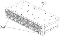
Fig. 11 and 12 are schematic structural diagrams of a chassis head according to an embodiment of the present invention.
Fig. 13 is a schematic view of the assembly of the chassis base and the chassis head according to an embodiment of the present invention.
Description of the element reference numerals
100 chassis
110 hard disk frame
200 case
210 chassis base
211 first accommodation space
212 second accommodation space
213 bottom plate
214 first side plate
215 second side plate
216 control module
217 cover plate
218 connecting hole
220 casing head
221 casing
222 backplane
223 hard disk bracket
224 connecting member
225 connecting hole
Detailed Description
The following description is provided for illustrative purposes, and other advantages and features of the present invention will become apparent to those skilled in the art from the following detailed description.
Please refer to fig. 7 to fig. 13. It should be understood that the structure, ratio, size and the like shown in the drawings attached to the present specification are only used for matching with the content disclosed in the specification, so as to be known and read by those skilled in the art, and are not used for limiting the limit conditions that the present invention can be implemented, so that the present invention has no technical essential meaning, and any structure modification, ratio relationship change or size adjustment should still fall within the scope that the technical content disclosed in the present invention can cover without affecting the function that the present invention can produce and the purpose that the present invention can achieve. Meanwhile, the terms such as "upper", "lower", "left", "right", "middle" and "one" used in the present specification are for convenience of description, and are not intended to limit the scope of the present invention, and changes or adjustments of the relative relationship thereof may be made without substantial technical changes, and the present invention is also regarded as the scope of the present invention.
In the prior design of the chassis, the type of the hard disk bracket required to be supported must be determined, so as to design the corresponding hard disk frame. Even through a large number of customer interviews and market research, it is difficult to determine which hard disk tray fits most customers. The chassis design lacks flexibility. Once the design of the hard disk frame is completed, the types of the hard disk brackets which can be supported are fixed, and the hard disk brackets with different sizes can not be supported. If the customer is not satisfied with the current hard disk carrier, the entire chassis must be modified to support the new hard disk carrier. The time cost consumption will be greatly increased.
An object of this embodiment is to provide a chassis and an electronic device applied thereto, for solving the problem that the whole chassis needs to be replaced to adapt to different hard disk brackets in the prior art. The principle and the implementation of the case and the electronic device applied thereto according to the present embodiment will be described in detail below, so that those skilled in the art can understand the case and the electronic device applied thereto without creative work.
As shown in fig. 7 and 8, the present embodiment provides a chassis 200, where the chassis 200 includes: a detachable chassis base 210 and a chassis head 220. In this embodiment, based on a common chassis base 210, only different chassis heads 220 need to be customized for different hard disk brackets 223, and the assembly of the entire chassis 200 is completed after the different chassis heads 220 are combined and fixed with the common chassis base 210. The enclosure 200 of the present embodiment can solve the problem that the entire enclosure 200 needs to be replaced to accommodate different hard disk brackets 223.
The chassis base 210 and the chassis head 220 of the chassis 200 according to the present embodiment will be described in detail below.
As shown in fig. 9 and 10, the chassis base 210 has a first accommodating space 211 where at least one control module 216 is mounted, and a second accommodating space 212 formed by extending the first accommodating space 211 outward and accommodating the chassis head 220.
When the hard disk bracket 223 is adapted to different hard disk brackets, the control module 216 and the like in the first accommodating space 211 of the chassis base 210 are kept unchanged, and only the chassis head 220 of the second accommodating space 212 needs to be replaced.
Specifically, in this embodiment, the chassis base 210 includes a bottom plate 213 and two side plates located at two sides of the bottom plate 213; the bottom plate 213 and the two side plates form the first accommodating space 211 and the second accommodating space 212.
The two side plates and the bottom plate 213 may be fixedly connected by screws or fasteners, or may be an integral structure, and the first accommodating space 211 may control the module 216, or may be used to place different functional modules such as a power module and a fan module.
The two side plates of the chassis 200 are provided with slide rails, so that the box body of the chassis 200 can slide relative to the slide grooves arranged on the slide rails. The chassis 200 can be pulled out by the slide rails on the two sides of the chassis 200, and functional modules such as a storage hard disk and a control module 216 in the chassis 200 are maintained.
Wherein, a cover plate 217 is installed on the top of the first accommodating space 211. The cover plate 217 is formed by assembling a plurality of small upper covers or the cover plate 217 can be of an integral structure, and the cover plate 217 and the bottom plate 213 are arranged on the top of the case 200 in a manner of being opposite to each other.
That is, the first accommodating space 211 in the chassis base 210, the control module 216 disposed in the first accommodating space 211, and the cover plate 217 covering the control module 216 form a fixed module, and the whole fixed module is kept unchanged each time when being adapted to different hard disk brackets 223. The bottom plate 213 of the chassis base 210 is opposite to the redundant bottom plate 213 of the whole fixed module, and the redundant side plate parts of the two side plates are opposite to the redundant side plate parts of the whole fixed module, so that the second accommodating space 212 is formed.
That is, in the embodiment, the chassis base 210 needs to protrude a certain length toward the chassis head 220 to form the second accommodating space 212, so that it is strong enough to lift the entire chassis head 220. The lengths of the redundant bottom plate 213 and the redundant side plate need to be selected according to the longest and shortest among all the hard disk trays 223 to be supported. That is, the shortest disk tray 223 can be carried, and the longest disk tray 223 can be carried. For example, the length of the hard disk tray 223 matches the length of the hard disk tray 223 with the largest length among the hard disk trays 223 that are conventional at present. It may be shorter than the length of the hard disk tray 223 having the largest length, but have sufficient supporting force to support the chassis head 220.
In this embodiment, the length of the second accommodating space 212 is preferably in the range of 100mm to 250 mm. As can be seen from fig. 2 to 6, the length of the hard disk tray 223 is 121.8mm, and may also be 180.68mm, or 204.8 mm. The length of the second accommodating space 212 is the length of the above-mentioned excess bottom plate 213 portion and excess side plate portion.
As can be seen, the chassis base 210 in this embodiment is a universal design or a common part, and only needs to be designed once.
As shown in fig. 11 and 12, the chassis head 220 is connected to the second accommodating space 212, and includes a housing 221 for mounting a hard disk bracket 223, and a plurality of hard disk brackets 223 are mounted in the housing 221.
In this embodiment, the width of the housing 221 is matched with the width of the second accommodating space 212; the height and length of the housing 221 are matched to those of the hard disk tray 223 assembled.
To support the hard disk holders 223 of different lengths, the chassis head 220 may be modified according to the size of the hard disk holder 223.
That is, the housing 221 may be redesigned and selected according to the hard disk bracket 223 to be assembled, so as to be adapted to the hard disk bracket 223. Then, the case head 220 fitted with the corresponding hard disk bracket 223 is assembled with the general case base 210 to form the complete case 200. Therefore, when the chassis 200 of the embodiment is modified, the whole chassis 200 does not need to be replaced again, and the design of the whole chassis 200 can be completed only by customizing different chassis heads 220 for different hard disk brackets 223 and then connecting and fixing the chassis heads 220 and the chassis base 210. The development cost of the chassis 200 is saved, and the development period is shortened.
Moreover, when the user replaces the chassis 200, the user can reuse the existing hard disk bracket 223 without purchasing a new one, thereby saving the cost of the customer and improving the satisfaction of the customer.
In this embodiment, the chassis head 220 further includes a back panel 222 disposed in the chassis 221 for connecting with the control module 216 in the chassis base 210. The structural configuration of the back plate 222 corresponds to the connection end of the control module 216 connected thereto.
That is, in this embodiment, the interface of the backplane 222 may be connected with the control module 216 of the server or the memory. Additionally, a cable connection may be used for the purpose of simply connecting signals associated with a hard disk within chassis head 220 from control module 216 to backplane 222.
In the present embodiment, as shown in fig. 13, the housing 221 is connected to the chassis base 210 through a connecting member 224.
Specifically, the connecting member 224 is a screw or a bolt; the side wall of the casing 221 and the two side plates of the chassis base 210 are respectively provided with a connection hole 218 and a connection hole 225 through which the screw or the bolt passes to achieve connection.
For example, the case head 220 and the case base 210 are fixed by screws.
The assembly and replacement processes of the chassis 200 in this embodiment are as follows:
designing a case head 220 with a corresponding size according to the size of a hard disk bracket 223, installing the hard disk bracket 223 in the case head 220, then installing the case head 220 in the second accommodating space 212 of the case base 210, connecting the back plate 222 of the case head 220 with the control module 216 in the case base 210, and then fixing the case head 220 by screws and the like.
If the case head 220 needs to be replaced, the control module 216 in the case base 210 is pulled out, the connection between the back plate 222 of the case head 220 and the control module 216 is disconnected, the screws for connecting the case head 220 and the case base 210 are disassembled, then the case head 220 is taken out from the case base 210, and the case head 220 is disassembled.
Therefore, when the chassis 200 in this embodiment is replaced, the whole chassis 200 does not need to be replaced again, and the design of the whole chassis 200 can be completed only by customizing different chassis heads 220 for different hard disk brackets 223 and then connecting and fixing the chassis heads 220 and the chassis base 210.
The utility model also provides an electronic device, electronic device is used as above quick-witted case 200. The electronic device is, for example, a server or a memory. And will not be described in detail herein.
To sum up, the utility model discloses a machine case includes but machine case base and the quick-witted case head of split to the quick-witted case head of a general machine case base assembly equidimension not forms the quick-witted case of the different hard disk bracket of adaptation, can dispose different machine case heads according to the size of a dimension of hard disk bracket, has saved whole quick-witted case development cost, has shortened development cycle, and the customer can reuse current existing hard disk bracket when the system upgrade, need not to purchase newly, thereby for saving customer's cost, improve customer satisfaction. Therefore, the utility model effectively overcomes various defects in the prior art and has high industrial utilization value.
The above embodiments are merely illustrative of the principles and effects of the present invention, and are not to be construed as limiting the invention. Modifications and variations can be made to the above-described embodiments by those skilled in the art without departing from the spirit and scope of the present invention. Accordingly, it is intended that all equivalent modifications or changes which may be made by those skilled in the art without departing from the spirit and technical spirit of the present invention be covered by the claims of the present invention.
Claims (10)
1. A chassis, its characterized in that: the method comprises the following steps: a detachable chassis base and a chassis head;
the chassis base is provided with a first accommodating space for assembling at least one control module and a second accommodating space formed by extending the first accommodating space outwards and used for accommodating the chassis head;
the case head is connected to the second accommodating space and includes a case for mounting a hard disk tray.
2. A cabinet according to claim 1, wherein: the chassis base comprises a bottom plate and two side plates positioned on two sides of the bottom plate; the bottom plate and the two side plates form the first accommodating space and the second accommodating space.
3. A cabinet according to claim 1, wherein: the width of the shell is matched with the width of the second accommodating space; the height and the length of the shell are matched with those of the assembled hard disk bracket.
4. A cabinet according to claim 1, wherein: the case head further includes: and the back plate is arranged in the machine shell and is used for being connected with the control module in the chassis base.
5. A cabinet according to claim 1 or 4, wherein: a plurality of hard disk brackets are assembled in the shell.
6. A cabinet according to claim 2, wherein: the case is connected with the chassis base through a connecting member.
7. A cabinet according to claim 6, wherein: the connecting component is a screw or a bolt; the side wall of the casing and the two side plates of the chassis base are respectively provided with a connecting hole for the screw or the bolt to pass through for realizing connection.
8. A cabinet according to claim 1, wherein: the top of the first accommodating space is provided with a cover plate.
9. A cabinet according to claim 1, wherein: the length range of the second accommodating space is 100 mm-250 mm.
10. An electronic device, characterized in that: the electronic device is applied to the chassis of any one of claims 1 to 9.
Priority Applications (1)
| Application Number | Priority Date | Filing Date | Title |
|---|---|---|---|
| CN201921862861.5U CN210804207U (en) | 2019-10-31 | 2019-10-31 | Case and electronic device applied to same |
Applications Claiming Priority (1)
| Application Number | Priority Date | Filing Date | Title |
|---|---|---|---|
| CN201921862861.5U CN210804207U (en) | 2019-10-31 | 2019-10-31 | Case and electronic device applied to same |
Publications (1)
| Publication Number | Publication Date |
|---|---|
| CN210804207U true CN210804207U (en) | 2020-06-19 |
Family
ID=71232308
Family Applications (1)
| Application Number | Title | Priority Date | Filing Date |
|---|---|---|---|
| CN201921862861.5U Active CN210804207U (en) | 2019-10-31 | 2019-10-31 | Case and electronic device applied to same |
Country Status (1)
| Country | Link |
|---|---|
| CN (1) | CN210804207U (en) |
Cited By (1)
| Publication number | Priority date | Publication date | Assignee | Title |
|---|---|---|---|---|
| CN110794935A (en) * | 2019-10-31 | 2020-02-14 | 加弘科技咨询(上海)有限公司 | A case and an electronic device using the same |
-
2019
- 2019-10-31 CN CN201921862861.5U patent/CN210804207U/en active Active
Cited By (1)
| Publication number | Priority date | Publication date | Assignee | Title |
|---|---|---|---|---|
| CN110794935A (en) * | 2019-10-31 | 2020-02-14 | 加弘科技咨询(上海)有限公司 | A case and an electronic device using the same |
Similar Documents
| Publication | Publication Date | Title |
|---|---|---|
| US6317318B1 (en) | Disk drive mounting structure for computers and method for mounting a disk drive to a computer chassis | |
| US5740020A (en) | Computer housing and expansion card format for consumer electronics devices | |
| US6088224A (en) | Cabinet for storing a plurality of processing unit modules | |
| US9179572B2 (en) | Server | |
| US6580604B1 (en) | Peripheral device bay with adapter plates | |
| US20140153181A1 (en) | Rack-mount server assembly | |
| CN102017822B (en) | For the power supply module of server cabinet and the method for build-in services device rack power supply | |
| US8953326B2 (en) | Rack-mount server assembly | |
| US6404624B1 (en) | Structure for mounting electronic devices to a computer main body | |
| US20230333608A1 (en) | Casing structure | |
| CN210804207U (en) | Case and electronic device applied to same | |
| US20040130865A1 (en) | 1U rack mount equipment enclosure with increased structural support | |
| US20040113034A1 (en) | Mounting bracket for disk drive | |
| CN102736681A (en) | Installation support and electron device employing therewith | |
| US5579924A (en) | Accessory storage system and apparatus | |
| US8649172B2 (en) | Fixing assembly for fan module | |
| US20060133053A1 (en) | Computer enclosure | |
| US11681337B2 (en) | Modular hard drive receiving chassis member with vibration damping supports | |
| CN218100142U (en) | Host and industrial control system | |
| CN210466246U (en) | Multifunctional universal type machine case of industrial control machine | |
| CN110794935A (en) | A case and an electronic device using the same | |
| US20110304986A1 (en) | Power supply assembly | |
| CN202339521U (en) | NVR network storage server case with multiple power supply selectivity | |
| CN201054107Y (en) | Enclosure structure of data server | |
| JP5467100B2 (en) | Fan for computer element in inspection position |
Legal Events
| Date | Code | Title | Description |
|---|---|---|---|
| GR01 | Patent grant | ||
| GR01 | Patent grant |