CN210728400U - A clinical gynecological treatment of infertility cervical dilator - Google Patents
A clinical gynecological treatment of infertility cervical dilator Download PDFInfo
- Publication number
- CN210728400U CN210728400U CN201920129710.2U CN201920129710U CN210728400U CN 210728400 U CN210728400 U CN 210728400U CN 201920129710 U CN201920129710 U CN 201920129710U CN 210728400 U CN210728400 U CN 210728400U
- Authority
- CN
- China
- Prior art keywords
- clamp body
- fixing plate
- dilation
- forceps body
- forceps
- Prior art date
- Legal status (The legal status is an assumption and is not a legal conclusion. Google has not performed a legal analysis and makes no representation as to the accuracy of the status listed.)
- Expired - Fee Related
Links
- 208000000509 infertility Diseases 0.000 title claims abstract description 22
- 230000036512 infertility Effects 0.000 title claims abstract description 22
- 231100000535 infertility Toxicity 0.000 title claims abstract description 22
- 230000010339 dilation Effects 0.000 claims abstract description 33
- 238000003780 insertion Methods 0.000 abstract description 8
- 230000037431 insertion Effects 0.000 abstract description 8
- 238000013461 design Methods 0.000 abstract description 4
- 210000003679 cervix uteri Anatomy 0.000 description 12
- 238000005457 optimization Methods 0.000 description 5
- 230000007812 deficiency Effects 0.000 description 3
- 238000010586 diagram Methods 0.000 description 3
- 208000031481 Pathologic Constriction Diseases 0.000 description 2
- 238000000034 method Methods 0.000 description 2
- 238000012986 modification Methods 0.000 description 2
- 230000004048 modification Effects 0.000 description 2
- 230000036262 stenosis Effects 0.000 description 2
- 208000037804 stenosis Diseases 0.000 description 2
- 208000007984 Female Infertility Diseases 0.000 description 1
- 206010021928 Infertility female Diseases 0.000 description 1
- 206010067268 Post procedural infection Diseases 0.000 description 1
- 210000003484 anatomy Anatomy 0.000 description 1
- 210000003756 cervix mucus Anatomy 0.000 description 1
- 230000000916 dilatatory effect Effects 0.000 description 1
- 201000010099 disease Diseases 0.000 description 1
- 208000037265 diseases, disorders, signs and symptoms Diseases 0.000 description 1
- 230000000694 effects Effects 0.000 description 1
- 230000035479 physiological effects, processes and functions Effects 0.000 description 1
- 238000011160 research Methods 0.000 description 1
- 210000000582 semen Anatomy 0.000 description 1
- 230000008010 sperm capacitation Effects 0.000 description 1
Images


Landscapes
- Surgical Instruments (AREA)
Abstract
本实用新型提供了一种临床妇科治疗不孕不育宫颈扩张器,包括:扩张钳本体、右钳体、左钳体、扩张头;所述扩张钳本体由右钳体及左钳体构成,且右钳体及左钳体通过转轴相连接;所述右钳体及左钳体的前端均设置有扩张头,且扩张头呈弧形弯曲状结构;所述右钳体及左钳体的后端均设置有夹持环,且夹持环呈圆环状结构;所述左钳体上设置有固定板,且固定板与左钳体通过固定方式相连接;本实用新型通过对临床妇科治疗不孕不育宫颈扩张器的改进,具有结构设计合理,方便插入,无需更换不同直径的扩张棒,减轻患者痛苦,便于控制扩张角度的优点,从而有效的解决了现有装置出现的问题和不足。
The utility model provides a clinical gynecological treatment of infertility cervical dilator, comprising: a dilation forceps body, a right forceps body, a left forceps body and a dilation head; the dilation forceps body is composed of a right forceps body and a left forceps body, And the right clamp body and the left clamp body are connected by a rotating shaft; the front ends of the right clamp body and the left clamp body are both provided with an expansion head, and the expansion head is in an arc-shaped curved structure; the right clamp body and the left clamp body are The rear end is provided with a clamping ring, and the clamping ring is in a circular structure; a fixing plate is arranged on the left forceps body, and the fixing plate is connected with the left forceps body in a fixed manner; The improvement of the cervical dilator for the treatment of infertility has the advantages of reasonable structural design, convenient insertion, no need to replace dilation rods of different diameters, alleviating the pain of patients, and easy control of the dilation angle, thus effectively solving the problems and problems of the existing device. insufficient.
Description
技术领域technical field
本实用新型涉及医疗器械技术领域,更具体的说,尤其涉及一种临床妇科治疗不孕不育宫颈扩张器。The utility model relates to the technical field of medical devices, in particular to a clinical gynecological cervical dilator for treating infertility.
背景技术Background technique
宫颈狭窄是导致女性不孕的原因之一。宫颈的形态和宫颈黏液的功能直接影响能否有相当数量的精子上游入宫腔获能,宫颈器质性或功能性疾病影响了精液或精子进入并储存在宫颈管内。子宫颈作为精子通过的第一道关隘,其解剖生理上的任何改变均可以影响精子的通过而致不孕。Cervical stenosis is one of the causes of female infertility. The morphology of the cervix and the function of the cervical mucus directly affect whether a considerable amount of sperm can enter the uterine cavity for capacitation, and organic or functional diseases of the cervix affect the entry and storage of semen or sperm in the cervical canal. The cervix is the first pass for sperm, and any changes in its anatomy and physiology can affect the passage of sperm and cause infertility.
宫颈口狭窄,需要做扩宫术,扩宫术就是用医疗器械扩张宫颈口。用于对宫颈扩张的医疗器械主要是扩张棒及扩张钳,使用扩张棒时,需要使用直径由小及大即由细及粗的不同规格的一组扩张棒,因而必须多次插入并拔出,易擦伤宫颈,增加术后感染几率,并且手术时间相对冗长;而目前使用的扩张钳不能很好的控制扩张角度,扩张效果差。Cervical stenosis requires dilation, which is to dilate the cervix with medical devices. The medical devices used to dilate the cervix are mainly dilation rods and dilation forceps. When using dilation rods, a set of dilation rods of different specifications with diameters ranging from small to large, that is, from thin to thick, must be inserted and pulled out multiple times. , it is easy to scratch the cervix, increase the probability of postoperative infection, and the operation time is relatively long; and the currently used dilation forceps cannot control the dilation angle well, and the dilation effect is poor.
有鉴于此,针对现有的问题予以研究改良,提供一种临床妇科治疗不孕不育宫颈扩张器,来解决目前存在的需要多次插入不同直径的扩张棒,以及扩张钳不能控制扩张角度的问题,旨在通过该技术,达到解决问题与提高实用价值性的目的。In view of this, research and improvement are made in view of the existing problems, and a clinical gynecological treatment of infertility cervical dilator is provided to solve the current need to insert dilation rods of different diameters multiple times, and the dilation forceps cannot control the dilation angle. The purpose is to solve the problem and improve the practical value through this technology.
实用新型内容Utility model content
本实用新型的目的在于提供一种临床妇科治疗不孕不育宫颈扩张器,以解决上述背景技术中提出的需要多次插入不同直径的扩张棒,以及扩张钳不能控制扩张角度的问题和不足。The purpose of this utility model is to provide a clinical gynecological treatment of infertility cervical dilator to solve the problems and deficiencies of the above-mentioned background technology that requires multiple insertion of dilation rods of different diameters and the inability of dilation forceps to control the dilation angle.
为实现上述目的,本实用新型提供了一种临床妇科治疗不孕不育宫颈扩张器,由以下具体技术手段所达成:In order to achieve the above object, the utility model provides a clinical gynecological treatment infertility cervical dilator, which is achieved by the following specific technical means:
一种临床妇科治疗不孕不育宫颈扩张器,包括:扩张钳本体、右钳体、左钳体、扩张头、夹持环、固定板、指针台、刻度、滑槽、滑轴、旋钮;所述扩张钳本体由右钳体及左钳体构成,且右钳体及左钳体通过转轴相连接;所述右钳体及左钳体的前端均设置有扩张头,且扩张头呈弧形弯曲状结构;所述右钳体及左钳体的后端均设置有夹持环,且夹持环呈圆环状结构;所述左钳体上设置有固定板,且固定板与左钳体通过固定方式相连接;所述固定板的上方设置有指针台,且指针台与右钳体为一体式结构;所述固定板设置有刻度及滑槽;所述滑槽的内部设置有滑轴,且滑轴与右钳体通过固定方式相连接;所述滑轴的顶端设置有旋钮,且旋钮与滑轴通过螺纹方式相连接。A cervical dilator for clinical gynecological treatment of infertility, comprising: a dilation forceps body, a right forceps body, a left forceps body, a dilation head, a clamping ring, a fixing plate, a pointer table, a scale, a chute, a sliding shaft, and a knob; The expansion forceps body is composed of a right forceps body and a left forceps body, and the right forceps body and the left forceps body are connected by a rotating shaft; the front ends of the right forceps body and the left forceps body are provided with expansion heads, and the expansion heads are arcs. The rear end of the right clamp body and the left clamp body are provided with a clamping ring, and the clamping ring has a circular structure; the left clamp body is provided with a fixing plate, and the fixing plate is connected to the left clamp body. The clamp bodies are connected in a fixed manner; a pointer table is arranged above the fixing plate, and the pointer table and the right clamp body are integrated into one structure; the fixing plate is provided with a scale and a chute; the inside of the chute is provided with The sliding shaft is connected with the right clamp body in a fixed manner; the top of the sliding shaft is provided with a knob, and the knob and the sliding shaft are connected by a thread.
作为本技术方案的进一步优化,本实用新型一种临床妇科治疗不孕不育宫颈扩张器所述右钳体与左钳体的扩张头的截面形状构成圆形,且右钳体与左钳体的扩张头顶端为球面结构。As a further optimization of the technical solution, the cross-sectional shapes of the expansion heads of the right forceps body and the left forceps body of a clinical gynecological cervical dilator for treating infertility of the present invention form a circle, and the right forceps body and the left forceps body are circular. The top of the expansion head is a spherical structure.
作为本技术方案的进一步优化,本实用新型一种临床妇科治疗不孕不育宫颈扩张器所述固定板的外形特征呈扇形环状结构,且固定板上设置有长圆弧形状的滑槽。As a further optimization of the technical solution, the fixed plate of a clinical gynecological treatment of infertility cervical dilator of the present utility model has a fan-shaped annular structure, and the fixed plate is provided with an arc-shaped chute.
作为本技术方案的进一步优化,本实用新型一种临床妇科治疗不孕不育宫颈扩张器所述指针台的顶面设置有凹陷的箭头,且指针台的下侧面与固定板的上侧面相配合。As a further optimization of this technical solution, a clinical gynecological cervical dilator for infertility treatment of the present invention is provided with a concave arrow on the top surface of the pointer table, and the lower side of the pointer table is matched with the upper side of the fixing plate .
作为本技术方案的进一步优化,本实用新型一种临床妇科治疗不孕不育宫颈扩张器所述固定板的上侧设置有刻度。As a further optimization of the technical solution, a scale is provided on the upper side of the fixed plate of a clinical gynecological cervical dilator for infertility treatment of the present invention.
作为本技术方案的进一步优化,本实用新型一种临床妇科治疗不孕不育宫颈扩张器所述滑轴的顶端螺纹,且所述螺纹与旋钮相配合。As a further optimization of the technical solution, the utility model provides a top thread of the sliding shaft of a clinical gynecological cervical dilator for treating infertility, and the thread is matched with the knob.
由于上述技术方案的运用,本实用新型与现有技术相比具有下列优点:Due to the application of the above-mentioned technical solutions, the present invention has the following advantages compared with the prior art:
1、本实用新型通过扩张钳本体由右钳体及左钳体构成,且右钳体及左钳体通过转轴相连接的设置,使扩张器插入宫颈后,通过调整右钳体与左钳体的开合角度,进行不同程度的扩张,无需更换不同直径的扩张棒,减轻患者痛苦。1. In the present utility model, the dilating forceps body is composed of a right forceps body and a left forceps body, and the right forceps body and the left forceps body are connected by a rotating shaft. Different opening and closing angles can be carried out for different degrees of expansion, without the need to replace expansion rods of different diameters, reducing the pain of patients.
2、本实用新型通过右钳体与左钳体的扩张头的截面形状构成圆形,且右钳体与左钳体的扩张头顶端为球面结构的设置,方便扩张钳的插入,而且不伤害宫颈。2. The cross-sectional shape of the expansion head of the right clamp body and the left clamp body forms a circle, and the top ends of the expansion heads of the right clamp body and the left clamp body are spherical structures, which is convenient for the insertion of the expansion clamp and does not hurt cervix.
3、本实用新型通过固定板的外形特征呈扇形环状结构,且固定板上设置有长圆弧形状的滑槽的设置,便于控制右钳体与左钳体的开合。3. The utility model adopts the shape feature of the fixing plate to be a fan-shaped annular structure, and the fixing plate is provided with the arrangement of the long arc-shaped chute, which is convenient to control the opening and closing of the right clamp body and the left clamp body.
4、本实用新型通过指针台的顶面设置有凹陷的箭头,且固定板的上侧设置有刻度的设置,便于控制右钳体与左钳体的开合角度。4. In the present invention, the top surface of the pointer table is provided with a concave arrow, and the upper side of the fixing plate is provided with a scale setting, which is convenient to control the opening and closing angles of the right clamp body and the left clamp body.
5、本实用新型通过对临床妇科治疗不孕不育宫颈扩张器的改进,具有结构设计合理,方便插入,无需更换不同直径的扩张棒,减轻患者痛苦,便于控制扩张角度的优点,从而有效的解决了本实用新型在背景技术一项中提出的问题和不足。5. Through the improvement of the clinical gynecological treatment of infertility cervical dilator, the utility model has the advantages of reasonable structure design, convenient insertion, no need to replace dilation rods of different diameters, alleviating the pain of patients, and being convenient to control the dilation angle, thereby effectively The problems and deficiencies raised in the background art of the present invention are solved.
附图说明Description of drawings
构成本申请的一部分的附图用来提供对本实用新型的进一步理解,本实用新型的示意性实施例及其说明用于解释本实用新型,并不构成对本实用新型的不当限定。在附图中:The accompanying drawings constituting a part of the present application are used to provide further understanding of the present invention, and the schematic embodiments of the present invention and descriptions thereof are used to explain the present invention and do not constitute an improper limitation of the present invention. In the attached image:
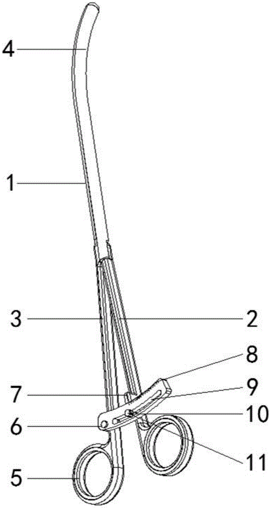
图1为本实用新型的结构示意图;Fig. 1 is the structural representation of the utility model;
图2为本实用新型的正视结构示意图;Fig. 2 is the front view structure schematic diagram of the utility model;
图3为本实用新型的张开一定角度后的结构示意图;Fig. 3 is the structural representation after opening a certain angle of the utility model;
图4为本实用新型的固定板结构示意图;4 is a schematic structural diagram of a fixed plate of the present invention;
图5为本实用新型的指针台结构示意图。FIG. 5 is a schematic diagram of the structure of the pointer table of the present invention.
图中:扩张钳本体1、右钳体2、左钳体3、扩张头4、夹持环5、固定板6、指针台7、刻度8、滑槽9、滑轴10、旋钮11。In the figure:
具体实施方式Detailed ways
下面将结合本实用新型实施例中的附图,对本实用新型实施例中的技术方案进行清楚、完整地描述,显然,所描述的实施例仅仅是本实用新型一部分实施例,而不是全部的实施例。The technical solutions in the embodiments of the present utility model will be clearly and completely described below with reference to the accompanying drawings in the embodiments of the present utility model. Obviously, the described embodiments are only a part of the embodiments of the present utility model, rather than all the implementations. example.
需要说明的是,在本实用新型的描述中,除非另有说明,“多个”的含义是两个或两个以上;术语“上”、“下”、“左”、“右”、“内”、“外”、“前端”、“后端”、“头部”、“尾部”等指示的方位或位置关系为基于附图所示的方位或位置关系,仅是为了便于描述本实用新型和简化描述,而不是指示或暗示所指的装置或元件必须具有特定的方位、以特定的方位构造和操作,因此不能理解为对本实用新型的限制。It should be noted that, in the description of the present utility model, unless otherwise specified, the meaning of "plurality" is two or more; the terms "upper", "lower", "left", "right", " The orientation or positional relationship indicated by "inside", "outside", "front end", "rear end", "head", "tail", etc. is based on the orientation or positional relationship shown in the accompanying drawings, and is only for the convenience of describing the present utility. The novel and simplified description does not indicate or imply that the device or element referred to must have a particular orientation, be constructed and operate in a particular orientation, and therefore should not be construed as limiting the invention.
此外,术语“第一”、“第二”、“第三”等仅用于描述目的,而不能理解为指示或暗示相对重要性。Furthermore, the terms "first," "second," "third," etc. are used for descriptive purposes only and should not be construed to indicate or imply relative importance.
同时,在本实用新型的描述中,除非另有明确的规定和限定,术语“相连”、“连接”应做广义理解,例如,可以是固定连接,也可以是可拆卸连接,或一体地连接;可以是机械连接,也可以是电性连接;可以是直接相连,也可以通过中间媒介间接相连。对于本领域的普通技术人员而言,可以具体情况理解上述术语在本实用新型中的具体含义。Meanwhile, in the description of the present invention, unless otherwise expressly specified and limited, the terms "connected" and "connected" should be understood in a broad sense, for example, it may be a fixed connection, a detachable connection, or an integral connection ; It can be a mechanical connection or an electrical connection; it can be directly connected or indirectly connected through an intermediate medium. For those of ordinary skill in the art, the specific meanings of the above terms in the present invention can be understood in specific situations.
请参见图1至图5,本实用新型提供一种临床妇科治疗不孕不育宫颈扩张器的具体技术实施方案:Please refer to Fig. 1 to Fig. 5, the present utility model provides a specific technical embodiment of a clinical gynecological treatment of infertility cervical dilator:
一种临床妇科治疗不孕不育宫颈扩张器,包括:扩张钳本体1、右钳体2、左钳体3、扩张头4、夹持环5、固定板6、指针台7、刻度8、滑槽9、滑轴10、旋钮11;扩张钳本体1由右钳体2及左钳体3构成,且右钳体2及左钳体3通过转轴相连接;右钳体2及左钳体3的前端均设置有扩张头4,且扩张头4呈弧形弯曲状结构;右钳体2及左钳体3的后端均设置有夹持环5,且夹持环呈圆环状结构;左钳体3上设置有固定板6,且固定板6与左钳体3通过固定方式相连接;固定板6的上方设置有指针台7,且指针台7与右钳体2为一体式结构;固定板6设置有刻度8及滑槽9;滑槽9的内部设置有滑轴10,且滑轴10与右钳体2通过固定方式相连接;滑轴10的顶端设置有旋钮11,且旋钮11与滑轴10 通过螺纹方式相连接。A cervical dilator for clinical gynecological treatment of infertility, comprising: a
具体的,右钳体2与左钳体3的扩张头4的截面形状构成圆形,且右钳体2 与左钳体3的扩张头4顶端为球面结构,方便扩张钳的插入,而且不伤害宫颈。Specifically, the cross-sectional shapes of the
具体的,固定板6的外形特征呈扇形环状结构,且固定板6上设置有长圆弧形状的滑槽9,便于控制右钳体2与左钳体3的开合。Specifically, the shape of the
具体的,指针台7的顶面设置有凹陷的箭头,且指针台7的下侧面与固定板 6的上侧面相配合,便于指示右钳体2与左钳体3的旋转角度。Specifically, the top surface of the pointer table 7 is provided with a concave arrow, and the lower side surface of the pointer table 7 is matched with the upper side surface of the
具体的,固定板6的上侧设置有刻度8,显示右钳体2与左钳体3的开合角度。Specifically, a
具体的,滑轴10的顶端螺纹,且所述螺纹与旋钮11相配合,通过旋钮锁紧张开的扩张钳。Specifically, the top end of the
具体实施步骤:Specific implementation steps:
在使用该临床妇科治疗不孕不育宫颈扩张器时,手持夹持环5,将扩张钳本体1送入宫颈口,圆弧状的扩张头4的顶面为球面结构,方便扩张钳的插入,而且不伤害宫颈,再根据患者的情况,根据固定板6的刻度8,慢慢调整右钳体2与左钳体3的展开角度,进行不同程度的扩张,无需更换不同直径的扩张棒,减轻患者痛苦,该临床妇科治疗不孕不育宫颈扩张器,具有结构设计合理,方便插入,无需更换不同直径的扩张棒,减轻患者痛苦,便于控制扩张角度的优点,从而满足了临床妇科的使用需求。When using the clinical gynecological treatment of infertility cervical dilator, hold the
综上所述:该一种临床妇科治疗不孕不育宫颈扩张器,通过扩张钳本体由右钳体及左钳体构成,且右钳体及左钳体通过转轴相连接的设置,使扩张器插入宫颈后,通过调整右钳体与左钳体的开合角度,进行不同程度的扩张,无需更换不同直径的扩张棒,减轻患者痛苦;通过右钳体与左钳体的扩张头的截面形状构成圆形,且右钳体与左钳体的扩张头顶端为球面结构的设置,方便扩张钳的插入,而且不伤害宫颈;通过固定板的外形特征呈扇形环状结构,且固定板上设置有长圆弧形状的滑槽的设置,便于控制右钳体与左钳体的开合;通过指针台的顶面设置有凹陷的箭头,且固定板的上侧设置有刻度的设置,便于控制右钳体与左钳体的开合角度;通过对临床妇科治疗不孕不育宫颈扩张器的改进,具有结构设计合理,方便插入,无需更换不同直径的扩张棒,减轻患者痛苦,便于控制扩张角度的优点,从而有效的解决了本实用新型在背景技术一项中提出的问题和不足。To sum up: the clinical gynecological treatment of infertility cervical dilator, the dilation forceps body is composed of a right forceps body and a left forceps body, and the right forceps body and the left forceps body are connected by a rotating shaft, so that the expansion can be achieved. After the device is inserted into the cervix, by adjusting the opening and closing angles of the right forceps body and the left forceps body, different degrees of expansion are performed, and there is no need to replace the expansion rods of different diameters, which relieves the pain of the patient; The shape is circular, and the tops of the expansion heads of the right forceps body and the left forceps body are spherical structures, which is convenient for the insertion of the expansion forceps, and does not hurt the cervix; The long arc-shaped chute is provided, which is convenient to control the opening and closing of the right clamp body and the left clamp body; the top surface of the pointer table is provided with a concave arrow, and the upper side of the fixed plate is provided with a scale setting, which is convenient for Control the opening and closing angles of the right forceps body and the left forceps body; through the improvement of the clinical gynecological treatment of infertility cervical dilator, it has a reasonable structure design, is easy to insert, does not need to replace the expansion rods of different diameters, reduces the pain of patients, and is easy to control The advantages of the expansion angle can effectively solve the problems and deficiencies proposed in the background art of the present invention.
尽管已经示出和描述了本实用新型的实施例,对于本领域的普通技术人员而言,可以理解在不脱离本实用新型的原理和精神的情况下可以对这些实施例进行多种变化、修改、替换和变型,本实用新型的范围由所附权利要求及其等同物限定。Although the embodiments of the present invention have been shown and described, it will be understood by those skilled in the art that various changes and modifications can be made to these embodiments without departing from the principles and spirit of the present invention , alternatives and modifications, the scope of the present invention is defined by the appended claims and their equivalents.
Claims (1)
Priority Applications (1)
| Application Number | Priority Date | Filing Date | Title |
|---|---|---|---|
| CN201920129710.2U CN210728400U (en) | 2019-01-25 | 2019-01-25 | A clinical gynecological treatment of infertility cervical dilator |
Applications Claiming Priority (1)
| Application Number | Priority Date | Filing Date | Title |
|---|---|---|---|
| CN201920129710.2U CN210728400U (en) | 2019-01-25 | 2019-01-25 | A clinical gynecological treatment of infertility cervical dilator |
Publications (1)
| Publication Number | Publication Date |
|---|---|
| CN210728400U true CN210728400U (en) | 2020-06-12 |
Family
ID=70978746
Family Applications (1)
| Application Number | Title | Priority Date | Filing Date |
|---|---|---|---|
| CN201920129710.2U Expired - Fee Related CN210728400U (en) | 2019-01-25 | 2019-01-25 | A clinical gynecological treatment of infertility cervical dilator |
Country Status (1)
| Country | Link |
|---|---|
| CN (1) | CN210728400U (en) |
Cited By (1)
| Publication number | Priority date | Publication date | Assignee | Title |
|---|---|---|---|---|
| CN113144395A (en) * | 2021-04-30 | 2021-07-23 | 全裕和 | Urethral dilator with better clinical adaptability for urology department |
-
2019
- 2019-01-25 CN CN201920129710.2U patent/CN210728400U/en not_active Expired - Fee Related
Cited By (1)
| Publication number | Priority date | Publication date | Assignee | Title |
|---|---|---|---|---|
| CN113144395A (en) * | 2021-04-30 | 2021-07-23 | 全裕和 | Urethral dilator with better clinical adaptability for urology department |
Similar Documents
| Publication | Publication Date | Title |
|---|---|---|
| CN109498129B (en) | An obstetric curettage device | |
| CN210728400U (en) | A clinical gynecological treatment of infertility cervical dilator | |
| CN211704788U (en) | Semi-disposable balloon uterine manipulator | |
| CN101254129B (en) | Multi-directional leak-free air lifter | |
| CN106821565B (en) | A kind of children's phimosis dilator | |
| CN206518763U (en) | Disposable painless uterus dilating stick | |
| CN209422067U (en) | A kind of freely adjustable artificial insemination conduit into cervix opening dynamics | |
| CN213249584U (en) | Uterine curettage device for obstetrics and gynecology department | |
| CN109549693A (en) | A kind of telescopic cervical dilator bar and application method | |
| CN210408567U (en) | A medical obstetrics and gynecology midwifery device | |
| CN215457888U (en) | Adjustable vaginal dilator for cervical and vaginal operations of fat patients | |
| CN111773524A (en) | A kind of elderly female catheterization aid device and method | |
| CN210644819U (en) | Perfusion control device of hysteroscope uterus expansion instrument | |
| CN209464134U (en) | A trial model for minimally invasive replacement of half hip joint | |
| CN206621379U (en) | A kind of fistula pribe | |
| CN221489930U (en) | Adjustable vaginal speculum suitable for obese patients | |
| CN217611651U (en) | Novel intrauterine device extractor for obstetrics and gynecology department | |
| CN201379889Y (en) | Improved cervical dilator | |
| CN206630656U (en) | Laparoscope cervical carcinoma operation uterus raising device | |
| CN203815550U (en) | Transvaginal hydrolaparoscopy (THL) puncturing sleeve | |
| CN219306965U (en) | Uterine lifter for gynecological clinical operation | |
| CN204050646U (en) | The intrauterine medicine slow-release device for the treatment of adenomyosis | |
| CN216702603U (en) | Gynecological operation forceps | |
| CN110522991A (en) | A foreskin dilator | |
| CN217744354U (en) | Vagina draw hook capable of being transversely expanded |
Legal Events
| Date | Code | Title | Description |
|---|---|---|---|
| GR01 | Patent grant | ||
| GR01 | Patent grant | ||
| CF01 | Termination of patent right due to non-payment of annual fee |
Granted publication date: 20200612 |
|
| CF01 | Termination of patent right due to non-payment of annual fee |