CN210573650U - A remote IoT intelligent control computer power supply - Google Patents
A remote IoT intelligent control computer power supply Download PDFInfo
- Publication number
- CN210573650U CN210573650U CN201921882031.9U CN201921882031U CN210573650U CN 210573650 U CN210573650 U CN 210573650U CN 201921882031 U CN201921882031 U CN 201921882031U CN 210573650 U CN210573650 U CN 210573650U
- Authority
- CN
- China
- Prior art keywords
- module
- remote
- power supply
- intelligent control
- control computer
- Prior art date
- Legal status (The legal status is an assumption and is not a legal conclusion. Google has not performed a legal analysis and makes no representation as to the accuracy of the status listed.)
- Active
Links
Images


Landscapes
- Power Sources (AREA)
Abstract
本实用新型提供一种远程物联智控电脑电源,包括电源主电路,所述电源主电路包括输入滤波整流模块、驱动模块、功率转换模块和输入滤波整流模块,通过功率转换模块使得驱动模块接通输入滤波整流模块和输入滤波整流模块,使得连接的电脑主机启动,还包括远程监控模块,所述远程监控模块包括远程开关模块,所述远程开关模块并接在功率转换模块上,通过远程开关模块也能使得驱动模块接通输入滤波整流模块和输入滤波整流模块。该远程物联智控电脑电源通过远程开关模块并接在常规的功率转换模块上,能够通过软开关开启电脑,也能通过远程开关模块开启电脑,即使人出门在外,也能配合现有的远程协助软件,可以随时随地的对个人电脑进行操作。
The utility model provides a remote IOT intelligent control computer power supply, comprising a main power supply circuit, wherein the main power supply circuit comprises an input filtering and rectifying module, a driving module, a power conversion module and an input filtering and rectifying module. Through the input filtering and rectifying module and the input filtering and rectifying module, the connected computer host is started, and the remote monitoring module also includes a remote monitoring module. The remote monitoring module includes a remote switch module. The module can also make the drive module connect to the input filtering and rectifying module and the input filtering and rectifying module. The remote IOT intelligent control computer power supply is connected to the conventional power conversion module through the remote switch module. It can turn on the computer through the soft switch, and can also turn on the computer through the remote switch module. Even if people go out, they can also cooperate with the existing remote The assistance software can operate the personal computer anytime, anywhere.
Description
技术领域technical field
本实用新型涉及电源装置技术领域,尤其涉及一种远程物联智控电脑电源。The utility model relates to the technical field of power supply devices, in particular to a remote IoT intelligent control computer power supply.
背景技术Background technique
电脑电源主要作用是将市电高压转为直流低压给主板及其他用电设备供电,是每台电脑的心脏,它的作用是将交流电变换为+5V、-5V、+12V、-12V、+3.3V等不同电压、稳定可靠的直流电,供给主机箱内的系统板、各种适配器和扩展卡、硬盘驱动器、光盘驱动器等系统部件及键盘和鼠标使用。The main function of the computer power supply is to convert the high voltage of the mains into the low voltage of DC to supply power to the motherboard and other electrical equipment. It is the heart of every computer. 3.3V and other different voltages, stable and reliable DC power, supply the system board, various adapters and expansion cards, hard disk drives, optical drives and other system components, as well as keyboards and mice in the main chassis.
普通的电脑电源只提供给电脑供电的基本功能,一般开启电脑时候,都是需要按下主机机箱位置的开关机键,必须人在现场的时候才能进行开机。Ordinary computer power supplies only provide the basic functions of powering the computer. Generally, when turning on the computer, it is necessary to press the power button on the position of the host chassis, and the power must be turned on when a person is on site.
工作效率如此重要的社会中,遇到需要调度工作文件的情况,这时候就需要第一时间使用到个人电脑。当不再办公室的情况下,通过远程协助软件对个人电脑进行操作,进行工作文件调度。但是,通常出门在外,办公室的个人电脑是关机的,即使远程协助软件能对个人电脑进行操作,但是电脑在关机状态下也无法运行该远程协助软件对电脑进行远程操作。In a society where work efficiency is so important, when you need to schedule work files, you need to use a personal computer for the first time. When no longer in the office, operate the personal computer through remote assistance software to schedule work files. However, usually when going out, the personal computer in the office is turned off. Even if the remote assistance software can operate the personal computer, the computer cannot run the remote assistance software to remotely operate the computer when the computer is off.
实用新型内容Utility model content
本实用新型的目的就在于为了解决上述问题而提供了一种远程物联智控电脑电源,能够远程地将电脑开启。The purpose of the present invention is to provide a remote IOT intelligent control computer power supply in order to solve the above problems, which can remotely turn on the computer.
本实用新型解决其技术问题所采用的技术方案是:The technical scheme adopted by the utility model to solve its technical problems is:
一种远程物联智控电脑电源,包括电源主电路,所述电源主电路包括输入滤波整流模块、驱动模块、功率转换模块和输入滤波整流模块,通过功率转换模块使得驱动模块接通输入滤波整流模块和输入滤波整流模块,使得连接的电脑主机启动,还包括远程监控模块,所述远程监控模块包括远程开关模块,所述远程开关模块并接在功率转换模块上,通过远程开关模块也能使得驱动模块接通输入滤波整流模块和输入滤波整流模块。A remote IoT intelligent control computer power supply includes a main power supply circuit, wherein the main power supply circuit includes an input filtering and rectifying module, a driving module, a power conversion module and an input filtering and rectifying module, and the driving module is connected to the input filtering and rectifying module through the power conversion module. module and input filtering and rectifying module to enable the connected computer host to start, and also include a remote monitoring module, the remote monitoring module includes a remote switch module, the remote switch module is connected to the power conversion module in parallel, and the remote switch module can also make The drive module is connected to the input filtering and rectifying module and the input filtering and rectifying module.
进一步的,所述远程监控模块包括中央处理器模块、远程开关模块和远程通信模块,所述中央处理器模块用于实现整个远程监控模块的控制逻辑,所述远程通信模块连接中央处理器模块,用于与外部通信设备进行远程通信,所述远程开关模块的输入端连接中央处理器模块,输入端并接在功率转换模块上。Further, the remote monitoring module includes a central processing unit module, a remote switching module and a remote communication module, the central processing unit module is used to implement the control logic of the entire remote monitoring module, and the remote communication module is connected to the central processing unit module, For remote communication with external communication equipment, the input end of the remote switch module is connected to the central processing unit module, and the input end is connected to the power conversion module in parallel.
进一步的,所述远程监控模块还包括数据采样模块,所述数据采样模块连接中央处理器模块,采集电源主电路的状态信息发送至中央处理器模块进行处理。Further, the remote monitoring module further includes a data sampling module, the data sampling module is connected to the central processing unit module, and the state information of the main circuit of the power supply is collected and sent to the central processing unit module for processing.
进一步的,所述远程通信模块采用WIFI通信。Further, the remote communication module adopts WIFI communication.
进一步的,所述外部通信设备为手机或电脑。Further, the external communication device is a mobile phone or a computer.
本实用新型的有益效果是:The beneficial effects of the present utility model are:
通过采用上述技术方案,本实用新型的远程物联智控电脑电源通过远程开关模块并接在常规的功率转换模块上,能够通过软开关开启电脑,也能通过远程开关模块开启电脑,即使人出门在外,也能配合现有的远程协助软件,可以随时随地的对个人电脑进行操作。By adopting the above technical solution, the remote IOT intelligent control computer power supply of the present invention is connected to the conventional power conversion module through the remote switch module, so that the computer can be turned on through the soft switch, and the computer can also be turned on through the remote switch module, even if people go out In addition, it can also cooperate with the existing remote assistance software, and can operate the personal computer anytime, anywhere.
附图说明Description of drawings
下面结合附图和实施例对本实用新型进一步说明。The present utility model will be further described below in conjunction with the accompanying drawings and embodiments.
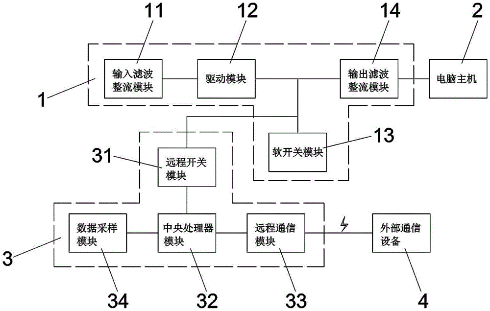
图1是本实用新型远程物联智控电脑电源的结构框图;Fig. 1 is the structural block diagram of the utility model remote IOT intelligent control computer power supply;
图2是本实用新型的远程监控模块的一种电路图;Fig. 2 is a kind of circuit diagram of the remote monitoring module of the present invention;
图3是在一种常规电脑电源电源主电路改进后的一种电路图。FIG. 3 is a circuit diagram after the main circuit of a conventional computer power supply is improved.
附图标记:1、电源主电路;11、输入滤波整流模块;12、驱动模块;13、功率转换模块;14、输入滤波整流模块;2、电脑主机;3、远程监控模块;31、远程开关模块;32、中央处理器模块;33、远程通信模块;34、数据采样模块;4、外部通信设备。Reference numerals: 1. Power main circuit; 11. Input filtering and rectifying module; 12. Driving module; 13. Power conversion module; 14. Input filtering and rectifying module; 2. Computer host; 3. Remote monitoring module; 31. Remote switch module; 32, central processing unit module; 33, remote communication module; 34, data sampling module; 4, external communication equipment.
具体实施方式Detailed ways
下面结合附图和具体实施例对本实用新型作进一步说明,以使本领域技术人员可以更好的理解本实用新型并能予以实施,但所举实施例不作为对本实用新型的限定。The present utility model will be further described below in conjunction with the accompanying drawings and specific embodiments, so that those skilled in the art can better understand the present utility model and implement it, but the examples are not intended to limit the present utility model.
如图1-2所示,一种远程物联智控电脑电源,包括电源主电路1,电源主电路1包括输入滤波整流模块11、驱动模块12、功率转换模块13和输入滤波整流模块14,通过功率转换模块13使得驱动模块12接通输入滤波整流模块11和输出滤波整流模块14,使得连接的电脑主机2启动,还包括远程监控模块3,远程监控模块3包括远程开关模块31,远程开关模块31并接在功率转换模块13上,通过远程开关模块31也能使得驱动模块12接通输入滤波整流模块11和输出滤波整流模块14。As shown in Figure 1-2, a remote IoT intelligent control computer power supply includes a main power supply circuit 1, and the main power supply circuit 1 includes an input filtering and rectifying
该远程物联智控电脑电源,将远程开关模块31并接在常规的功率转换模块13上,能通过远程开关模块31开启电脑。参考图3,图中为现有的比较常见的一种电脑电源LWT2005的电源主电路1改进后的一种电路图,将远程开关模块31并接与PS信号输入端并接。In the remote IOT intelligent control computer power supply, the
常规的LWT2005电路微机通电后,由主板送来的PS信号控制IC2的第4引脚(脉宽调制控制端)电压,待机时,主板启动控制电路的电子开关断开,PS信号输出高电平3.6V,经R37到达IC1(电压比较放大器LM339N)的第6引脚(启动端),由内部经IC1的第3引脚,对C35进行充电,同时IC1的第2引脚经R41送出一个比较电压给IC2的第4引脚,IC2的第4引脚电压由零电位开始逐渐上升,当上升的电压超过3V时,封锁IC2的第8、11引脚的调制脉宽电压输出,使T2推动变压器、T1主电源开关变压器停振,从而停止提供+3.3V、±5V、±12V等各路输出电压,电源处于待机状态。受控启动后,PS信号由主板启动控制电路的电子开关接地,IC1的第6引脚为低电平(0V),IC2的第4引脚变为低电平(0V),此时允许第8、11引脚输出脉宽调制信号。IC2的第13引脚(输出方式控制端)接稳压+5V (由IC2内部稳压输出+5V电压),脉宽调制器为并联推挽式输出,第8、11引脚输出相位差180度的脉宽调制信号,输出频率为IC2的第5、6引脚外接定时阻容元件R30、C30的振荡频率的一半,控制推动三极管Q3、Q4的c极连接的T2次级绕组的激励振荡。T2初级它激振荡产生的感应电动势作用于T1主电源开关变压器的初级绕组,从T1次级绕组的感应电动势整流输出+3.3V、±5V、±12V等各路输出电压,使得电脑主机2开启。After the conventional LWT2005 circuit microcomputer is powered on, the PS signal sent from the main board controls the voltage of the 4th pin (pulse width modulation control terminal) of IC2. When in standby, the electronic switch of the main board startup control circuit is turned off, and the PS signal outputs a high level 3.6V, reaches the 6th pin (start end) of IC1 (voltage comparison amplifier LM339N) via R37, and charges C35 internally via the 3rd pin of IC1, while the 2nd pin of IC1 sends a comparison via R41 The voltage is given to the 4th pin of IC2, and the voltage of the 4th pin of IC2 starts to rise gradually from zero potential. When the rising voltage exceeds 3V, the modulated pulse width voltage output of the 8th and 11th pins of IC2 is blocked, so that T2 pushes The transformer and T1 main power switch transformer stop vibrating, thereby stopping providing +3.3V, ±5V, ±12V and other output voltages, and the power supply is in a standby state. After the controlled startup, the PS signal is grounded by the electronic switch of the mainboard startup control circuit, the sixth pin of IC1 is low level (0V), and the fourth pin of IC2 becomes low level (0V). 8, 11 pin output pulse width modulation signal. The 13th pin of IC2 (output mode control terminal) is connected to +5V voltage regulator (+5V voltage is output by the internal voltage regulator of IC2), the pulse width modulator is a parallel push-pull output, and the output phase difference between the 8th and 11th pins is 180 The output frequency is half of the oscillation frequency of the external timing resistor-capacitor elements R30 and C30 on the 5th and 6th pins of IC2, and controls the excitation oscillation of the secondary winding of T2 connected to the c-poles of the transistors Q3 and Q4. . The induced electromotive force generated by T2's primary oscillation acts on the primary winding of the T1 main power switching transformer, and the induced electromotive force of the T1 secondary winding is rectified to output +3.3V, ±5V, ±12V and other output voltages, so that the
LWT2005电路改进后的电路具有两个信号输入端,PS信号输入端和远程开关模块31,远程开关模块31其中一端接地,触发远程开关模块31后,同样能使得IC1的第6引脚为低电平(0V),从而使得T1次级绕组的感应电动势整流输出+3.3V、±5V、±12V等各路输出电压,使得电脑主机2开启。The improved circuit of LWT2005 circuit has two signal input terminals, PS signal input terminal and
具体的,远程监控模块3包括中央处理器模块32、远程开关模块31和远程通信模块33,中央处理器模块32用于实现整个远程监控模块3的控制逻辑,远程通信模块33连接中央处理器模块31,用于与外部通信设备4进行远程通信,远程开关模块31的输入端连接中央处理器模块32,输入端并接在功率转换模块13上。通过外部通信设备4与远程通信模块33进行网络连接,外部通信设备4可以在远程触发远程开关模块31,达到远程开启电脑主机2的效果。其中,远程通信模块33一般与外部通信设备4采用WIFI通信;而外部通信设备4一般为手机。Specifically, the
此外,远程监控模块3还可以具有数据采样模块34,数据采样模34块连接中央处理器模块42,采集电源主电路1的电路电流、电压、效率等以及电脑电源的温度、风扇转速等状态信息发送至中央处理器模块32进行处理。In addition, the
本实用新型的上述实施例并不是对本实用新型保护范围的限定,本实用新型的实施方式不限于此,凡此种种根据本实用新型的上述内容,按照本领域的普通技术知识和惯用手段,在不脱离本实用新型上述基本技术思想前提下,对本实用新型上述结构做出的其它多种形式的修改、替换或变更,均应落在本实用新型的保护范围之内。The above-mentioned embodiments of the present invention are not intended to limit the protection scope of the present invention, and the embodiments of the present invention are not limited thereto. Under the premise of not departing from the above-mentioned basic technical idea of the present invention, other various modifications, replacements or changes made to the above-mentioned structure of the present invention should all fall within the protection scope of the present invention.
Claims (5)
Priority Applications (1)
| Application Number | Priority Date | Filing Date | Title |
|---|---|---|---|
| CN201921882031.9U CN210573650U (en) | 2019-11-04 | 2019-11-04 | A remote IoT intelligent control computer power supply |
Applications Claiming Priority (1)
| Application Number | Priority Date | Filing Date | Title |
|---|---|---|---|
| CN201921882031.9U CN210573650U (en) | 2019-11-04 | 2019-11-04 | A remote IoT intelligent control computer power supply |
Publications (1)
| Publication Number | Publication Date |
|---|---|
| CN210573650U true CN210573650U (en) | 2020-05-19 |
Family
ID=70661877
Family Applications (1)
| Application Number | Title | Priority Date | Filing Date |
|---|---|---|---|
| CN201921882031.9U Active CN210573650U (en) | 2019-11-04 | 2019-11-04 | A remote IoT intelligent control computer power supply |
Country Status (1)
| Country | Link |
|---|---|
| CN (1) | CN210573650U (en) |
-
2019
- 2019-11-04 CN CN201921882031.9U patent/CN210573650U/en active Active
Similar Documents
| Publication | Publication Date | Title |
|---|---|---|
| KR970000258B1 (en) | Computer Power Supply Control | |
| US8675891B2 (en) | Power supply unit with noise reduction capability | |
| US7930571B2 (en) | Information processing apparatus and power control method | |
| US20100067268A1 (en) | Systems and methods for controlling energy consumption of AC-DC adapters | |
| CN203366017U (en) | Building talk-back intelligent terminal and crash restart system for same | |
| WO2023077930A1 (en) | Linear motor driving method and circuit, and related apparatus | |
| CN102650904B (en) | Low power consumption circuit and method for reducing power consumption | |
| CN103064488A (en) | Power source control circuit | |
| CN216053092U (en) | Electronic wallet circuit and electronic wallet | |
| CN210573650U (en) | A remote IoT intelligent control computer power supply | |
| US20060230293A1 (en) | Device and method for powering a peripheral device | |
| CN115833414A (en) | Power supply circuit and electronic equipment | |
| CN103543643A (en) | Electric appliance standby power saving control circuit | |
| CN213043666U (en) | Low-power consumption standby electronic equipment | |
| CN111399617B (en) | Power supply control device and electronic apparatus | |
| CN112799496A (en) | Computer zero power consumption standby control device, method and system | |
| CN219916307U (en) | Computer power supply with power-off and energy-continuing functions | |
| EP1710662A1 (en) | Device and Method for Powering a Peripheral Device | |
| CN117318320A (en) | A self-powered line voltage measurement low-power energy control system and method | |
| CN101676825A (en) | Electronic system and power supply device thereof | |
| US20100067265A1 (en) | Electronic system and power supply device thereof | |
| CN108874106A (en) | A kind of BMC power control system, method and server | |
| WO2022267746A1 (en) | Circuit for peripheral device to wake up host and electronic device | |
| CN210129815U (en) | Working mode switching circuit and electronic equipment | |
| CN112649649A (en) | MCU chip power supply voltage detection circuit |
Legal Events
| Date | Code | Title | Description |
|---|---|---|---|
| GR01 | Patent grant | ||
| GR01 | Patent grant | ||
| CP03 | Change of name, title or address | ||
| CP03 | Change of name, title or address |
Address after: 510000 Guangdong Province Guangzhou City Baiyun District Xingshan North Road No. 65 Room 601, 701 Patentee after: Guangzhou Bray Electronic Technology Co.,Ltd. Country or region after: China Address before: 510000 Guangdong Province, Guangzhou City, Baiyun District, Zhongluotan Town, ZhuLiao Hongqi Village, Qinghong Road No. 38, 18th Patentee before: Guangzhou Bray Electronic Technology Co.,Ltd. Country or region before: China |