CN210446750U - Pot body supporting structure, pot body device and cooking machine - Google Patents
Pot body supporting structure, pot body device and cooking machine Download PDFInfo
- Publication number
- CN210446750U CN210446750U CN201920648916.6U CN201920648916U CN210446750U CN 210446750 U CN210446750 U CN 210446750U CN 201920648916 U CN201920648916 U CN 201920648916U CN 210446750 U CN210446750 U CN 210446750U
- Authority
- CN
- China
- Prior art keywords
- pot body
- shell
- heating
- pot
- drum
- Prior art date
- Legal status (The legal status is an assumption and is not a legal conclusion. Google has not performed a legal analysis and makes no representation as to the accuracy of the status listed.)
- Active
Links
- 238000010411 cooking Methods 0.000 title abstract description 10
- 238000010438 heat treatment Methods 0.000 claims abstract description 58
- 230000003014 reinforcing effect Effects 0.000 claims abstract description 38
- 238000005096 rolling process Methods 0.000 claims description 24
- 238000009434 installation Methods 0.000 abstract description 4
- 230000002349 favourable effect Effects 0.000 abstract description 2
- 230000017525 heat dissipation Effects 0.000 description 6
- 238000007664 blowing Methods 0.000 description 3
- 238000004804 winding Methods 0.000 description 3
- 235000021186 dishes Nutrition 0.000 description 2
- 235000013305 food Nutrition 0.000 description 2
- 239000000463 material Substances 0.000 description 2
- 238000005728 strengthening Methods 0.000 description 2
- 240000007594 Oryza sativa Species 0.000 description 1
- 235000007164 Oryza sativa Nutrition 0.000 description 1
- 239000011324 bead Substances 0.000 description 1
- 230000009286 beneficial effect Effects 0.000 description 1
- 238000009835 boiling Methods 0.000 description 1
- 235000005911 diet Nutrition 0.000 description 1
- 230000037213 diet Effects 0.000 description 1
- 230000005674 electromagnetic induction Effects 0.000 description 1
- 238000000034 method Methods 0.000 description 1
- 238000012986 modification Methods 0.000 description 1
- 230000004048 modification Effects 0.000 description 1
- 235000009566 rice Nutrition 0.000 description 1
- 238000010025 steaming Methods 0.000 description 1
Images


Landscapes
- Cookers (AREA)
Abstract
The utility model relates to a pot body bearing structure, pot body device and machine of cooking. The pot body supporting structure comprises a supporting shell, a plurality of first reinforcing ribs and a plurality of second reinforcing ribs. The inner wall of the supporting shell is used for being sleeved with the drum-type pot body, the outer wall of the supporting shell is provided with a heating groove, and the heating groove is used for installing a heating element. The first reinforcing rib is arranged on the outer wall of the supporting shell and positioned above the heating groove. The second reinforcing rib is arranged on the outer wall of the supporting shell and is positioned below the heating groove. The setting of heating tank can be favorable to heating element's stable installation, and the heating tank setting is at the outer wall of supporting the shell for heating element can heat the lateral part of the drum-type pot body, and not the bottom of the heating drum-type pot body, increases the heated area of the drum-type pot body, and is heated more evenly, can heat the drum-type pot body effectively.
Description
Technical Field
The utility model relates to a kitchen utensil equipment technical field especially relates to a pot body bearing structure, pot body device and machine of cooking.
Background
The cooker not only can cook but also has the functions of frying, stir-frying, cooking, frying, steaming, boiling, stewing, baking, cooking as well as making rice and cake. The popularization of the cooking machine is expected to cause a revolution in a kitchen, thereby fundamentally changing the diet concept and the life style of people.
Traditional machine of cooking borrows the heating method of reference pan, and the resistance wire is two-dimentional heliciform winding in pan bottom plane, makes frying pan self-heating through electromagnetic induction. However, the installation and winding manner of the electromagnetic heating is only limited to plane winding, and the serving object is a flat-bottomed frying pan, which cannot support and effectively heat the drum-type pan body.
SUMMERY OF THE UTILITY MODEL
Based on this, it is necessary to provide a pot body supporting structure, a pot body device and a cooking machine aiming at the problem that the drum-type pot body cannot be supported and effectively heated, wherein the pot body supporting structure
A pot body supporting structure comprises a supporting shell, a plurality of first reinforcing ribs and a plurality of second reinforcing ribs.
The inner wall of the supporting shell is used for being sleeved with the drum-type pot body, the outer wall of the supporting shell is provided with a heating groove, and the heating groove is used for installing a heating element. The first reinforcing rib is arranged on the outer wall of the supporting shell and positioned above the heating groove. The second reinforcing rib is arranged on the outer wall of the supporting shell and is positioned below the heating groove.
When the pot body supporting structure is used, the drum-type pot body is sleeved in the supporting shell, and the first reinforcing rib and the second reinforcing rib improve the mechanical strength of the supporting shell, so that the supporting shell effectively supports the drum-type pot body. The setting of heating tank can be favorable to heating element's stable installation, and the heating tank setting is at the outer wall of supporting the shell for heating element can heat the lateral part of the drum-type pot body, and not the bottom of the heating drum-type pot body, increases the heated area of the drum-type pot body, and is heated more evenly, can heat the drum-type pot body effectively.
In one embodiment, the supporting shell is further provided with a mounting through hole, the pot body supporting structure further comprises a rolling contact assembly, the rolling contact assembly comprises a connecting piece and a rolling piece, the connecting piece is mounted in the mounting through hole, the rolling piece is mounted on the connecting piece in a rolling mode, and part of the rolling piece protrudes out of the inner wall of the supporting shell.
In one embodiment, the mounting through hole comprises a first mounting hole and a second mounting hole which are adjacently arranged, the connecting piece comprises a connecting block and an auxiliary connecting piece connected with the connecting block, the rolling piece is mounted on the connecting block, the connecting block can be inserted into the first mounting hole, and the auxiliary connecting piece can be inserted into the second mounting hole.
In one embodiment, the auxiliary connecting piece comprises a connecting arm and a cantilever, one end of the connecting arm is connected with the connecting block, the other end of the connecting arm is connected with one end of the cantilever, and the other end of the cantilever is provided with a hook which can be clamped on the end face of the second mounting hole.
In one embodiment, the heating groove is disposed around a circumference of the support case.
In one embodiment, a plurality of the first reinforcing ribs are arranged at intervals along the circumferential direction of the support shell; and/or a plurality of second reinforcing ribs are arranged at intervals along the circumferential direction of the support shell.
In one embodiment, the pot body supporting structure further comprises a first mounting plate mounted on the outer wall of the supporting shell, the first mounting plate is positioned on the top of the first reinforcing rib, and the first mounting plate is used for being connected to a bracket of the pot body device.
In one embodiment, the pot body supporting structure further comprises a base installed at the bottom of the supporting shell, and the base is used for installing a rotary driving piece of the pot body device.
The pot body device comprises a drum-type pot body, a heating element and the pot body supporting structure, wherein the drum-type pot body is sleeved in the supporting shell, and the heating element is arranged in the heating groove.
A cooker comprises the pot body device.
Drawings
Fig. 1 is a schematic structural view of a cooker according to an embodiment of the present invention;
FIG. 2 is a schematic structural view of a pan body device of the cooker shown in FIG. 1;
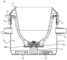
FIG. 3 is a cross-sectional view of the pan assembly of FIG. 2;
FIG. 4 is an exploded view of the pan assembly of FIG. 2;
FIG. 5 is a schematic view of a pan body support structure of the pan body apparatus shown in FIG. 2;
FIG. 6 is a schematic view showing the connection between the supporting shell of the pot body supporting structure in FIG. 5 and the first reinforcing rib and the second reinforcing rib;
FIG. 7 is a schematic view of the rolling contact assembly of the pan support structure of FIG. 5.
1. Frying machine, 10, pot body device, 11, the drum-type pot body, 12, the second mounting panel, 13, the shell, 14, the louvre, 15, blow the unit, 16, the heat dissipation channel, 17, the rotor arm, 18, the rotary driving piece, 100, the support shell, 110, the heating tank, 120, the mounting hole, 121, first mounting hole, 122, the second mounting hole, 20, the frame, 30, the controller, 40, the pot cover device, 200, the first strengthening rib, 300, the second strengthening rib, 400, the rolling contact subassembly, 410, the connecting piece, 411, the connecting block, 412, auxiliary connecting piece, 413, the connecting arm, 414, the cantilever, 415, the trip, 420, the rolling piece, 500, the first mounting panel, 600, the base.
Detailed Description
In order to facilitate understanding of the present invention, the present invention will be described more fully hereinafter with reference to the accompanying drawings. The preferred embodiments of the present invention are shown in the drawings. The invention may, however, be embodied in many different forms and should not be construed as limited to the embodiments set forth herein. Rather, these embodiments are provided so that this disclosure will be thorough and complete.
It will be understood that when an element is referred to as being "secured to" another element, it can be directly on the other element or intervening elements may also be present. When an element is referred to as being "connected" to another element, it can be directly connected to the other element or intervening elements may also be present. In contrast, when an element is referred to as being "directly on" another element, there are no intervening elements present. The terms "vertical," "horizontal," "left," "right," and the like as used herein are for illustrative purposes only. In the present invention, the terms "first", "second", "third" and "fourth" do not denote any particular quantity or order, but are merely used to distinguish names.
Fig. 1 shows a schematic structural view of a cooker 1. With reference to fig. 1, the cooker 1 comprises a pan device 10. Fig. 2 shows a schematic structural view of a pan device 10. Referring to fig. 2 to 4, the pot device 10 comprises a drum pot 11, a heating element (not shown) and a pot support structure.
Referring to fig. 5 and 6 together, a pot body supporting structure includes a supporting case 100, a plurality of first reinforcing ribs 200, and a plurality of second reinforcing ribs 300. The inner wall of the supporting shell 100 is used for sleeving the roller-type pot body 11. Wherein, the inner wall of the supporting shell 100 is attached to the outer wall of the drum-type pot body 11, the two ends of the supporting shell 100 are open, and the diameter of the supporting shell 100 is gradually reduced from top to bottom. The diameter of the top of the drum-type pot body 11 is larger than that of the top of the support shell 100, and the drum-type pot body 11 is automatically sleeved in the support shell 100 without falling off when being loaded into the support shell 100 from the top opening of the support shell 100.
Referring to fig. 5 and 6, the outer wall of the support case 100 is provided with a heating groove 110. The heating bath 110 is used to mount a heating element. The heating element may be selected as a solenoid. The heating bath 110 serves to wind and fix the electromagnetic coil. Self-heating of the drum-type pot body 11 is caused by the energized electromagnetic coil. The first reinforcing rib 200 is installed at the outer wall of the support case 100 and is positioned above the heating bath 110. The second reinforcing ribs 300 are installed at the outer wall of the support case 100 and are positioned below the heating bath 110. In this way, when the heating groove 110 is located at the lower half of the support case 100, the second reinforcing rib 300 is located at the lower half of the support case 100, and the first reinforcing rib 200 is installed at the upper half of the support case 100 or the lower half of the support case 100. Similarly, when the heating bath 110 is positioned at the upper half of the support case 100, the second reinforcing rib 300 is installed at the upper half of the support case 100 or the lower half of the support case 100.
When the pot body supporting structure is used, the drum type pot body 11 is sleeved in the supporting shell 100, and the first reinforcing rib 200 and the second reinforcing rib 300 improve the mechanical strength of the supporting shell 100, so that the supporting shell 100 effectively supports the drum type pot body 11. The arrangement of the heating groove 110 can be beneficial to the stable installation of the heating element, and the heating groove 110 is arranged on the outer wall of the supporting shell 100, so that the heating element can heat the side part of the drum-type pot body 11 instead of the bottom part of the drum-type pot body 11, the heating area of the drum-type pot body 11 is increased, the heating is more uniform, and the drum-type pot body 11 can be effectively heated.
Specifically, the heating bath 110 is located at the lower half of the support case 100. The food material is mainly positioned at the lower half part of the drum-type pot body 11, so that the heating area is more reasonable.
Wherein, referring to fig. 6, the heating groove 110 is disposed around the circumference of the supporting shell 100, so that the heating area of the roller-type pot body 11 is larger and the heating is more uniform.
Specifically, with continued reference to fig. 6, a plurality of first reinforcing ribs 200 are provided at intervals along the circumferential direction of the support shell 100; and/or, a plurality of second reinforcing beads 300 are provided at intervals along the circumferential direction of the support case 100. The first reinforcing ribs 200 and the second reinforcing ribs 300 are distributed, so that the overall stress condition of the support housing 100 can be improved, and the mechanical strength of the support housing 100 can be improved. Wherein, the first reinforcing rib 200 and the second reinforcing rib 300 are welded to the support shell 100, or the first reinforcing rib 200, the second reinforcing rib 300 and the support shell 100 are integrally formed, so as to ensure that the pot body support structure has sufficient mechanical strength.
In one embodiment, referring to fig. 1 and 3, the pot device 10 further comprises a housing 13, a bracket (not shown), a turning arm 17, a rotary drive 18 and a blowing unit 15. The swivel arm 17 is fixed to the outer wall of the housing 13. The shell 13 is rotatably mounted on the frame 20 through a rotating arm 17, so that the drum-type pot body 11 can be turned over to automatically pour dishes. The support housing 100 is fitted inside the outer housing 13, and the support housing 100 is connected to the outer housing 13 by a bracket. The support case 100 and the inner wall of the housing 13 have a gap therebetween, which forms the heat dissipation channel 16. At one end of the heat dissipation channel 16, a blowing unit 15, such as a fan, is provided between the support case 100 and the outer case 13. At the other end of the heat dissipation channel 16, heat dissipation holes 14 are formed on the side wall of the housing 13.
Referring also to fig. 6, the supporting structure of the pot body further includes a first mounting plate 500 mounted on the outer wall of the supporting shell 100, the first mounting plate 500 is located on the top of the first reinforcing rib 200, and the first mounting plate 500 is used for being connected to the bracket of the pot body assembly 10. Specifically, referring to fig. 3, the bracket includes a second mounting plate 12. The first mounting plate 500 and the second mounting plate 12 are connected by fasteners.
In one embodiment, with reference to fig. 3, 5 and 6, the pot body support structure further comprises a base 600 mounted to the bottom of the support shell 100. Base 600 is used to mount rotary drive member 18 of pan unit 10. Pot assembly 10 further includes a stirrer (not shown). The main body of the stirrer is positioned in the drum-type pot body 11. The bottom end of the agitator is connected to the output end of the rotary drive member 18. The rotary driving member 18 drives the stirrer to rotate, and the food materials can be stirred. The rotary drive member 18 may alternatively be a rotary motor such as an ac servo motor, an ac asynchronous motor, a dc permanent magnet motor, a dc brushless motor and a dc stepper motor.
Wherein, blowing unit 15 is located the below of heat dissipation passageway 16, and louvre 14 is located the top of passageway, and the heat is discharged from bottom to top, is convenient for rise the heat of drum-type pot body 11 lower part to the top of drum-type pot body 11, is that drum-type pot body 11 is whole to be heated, and make full use of heat also avoids the heat to sink to rotary driving piece 18, influences rotary driving piece 18's performance.
Specifically, referring to fig. 5, 6 and 7, the supporting shell 100 is further provided with a mounting through hole 120, the pot body supporting structure further comprises a rolling contact assembly 400, the rolling contact assembly 400 comprises a connecting member 410 and a rolling member 420, the connecting member 410 is mounted in the mounting through hole 120, the rolling member 420 is rollably mounted on the connecting member 410, and the rolling member 420 partially protrudes from the inner wall of the supporting shell 100. Thus, the roller-type pot body 11 can be in rolling contact with the rolling element 420, so that the roller-type pot body 11 can rotate around the axis of the roller-type pot body. The drum-type pot body 11 can realize the cooking operation means such as stir-frying through rotating, so that the frying machine 1 can prepare various dishes.
Further, referring to fig. 5, 6 and 7, the mounting through-hole 120 includes a first mounting hole 121 and a second mounting hole 122 disposed adjacent to each other, the connection member 410 includes a connection block 411 and an auxiliary connection member 412 connected to the connection block 411, and the rolling member 420 is mounted to the connection block 411. The connection block 411 may be inserted into the first mounting hole 121, and the auxiliary connection member 412 may be inserted into the second mounting hole 122. Thus, the connection block 411 and the auxiliary connection member 412 are convenient to install and assemble and disassemble by inserting. Wherein, both sides of the first mounting hole 121 are provided with second mounting holes 122.
Further, referring to fig. 5, 6 and 7, the auxiliary connecting member 412 includes a connecting arm 413 and a cantilever 414. One end of the connecting arm 413 is connected to the connecting block 411, and the other end is connected to one end of the cantilever 414. The other end of the cantilever 414 is provided with a hook 415, and the hook 415 can be clamped on the end surface of the second mounting hole 122. The hook 415 is located at the free end of the cantilever 414, so that the hook 415 can be elastically displaced, and the hook 415 can conveniently hold the end surface of the second mounting hole 122 or the auxiliary connecting member 412 can be conveniently detached from the second mounting hole 122.
Referring back to fig. 1, the pot assembly 10 may further include a frame 20, a controller 30, and a pot lid assembly 40. Optionally, the pan unit 10 is rotatably mounted to the frame 20. The controller 30 and the pot cover device 40 are both installed on the frame 20, and the pot cover of the pot cover device 40 can be rotated to open or close the pot opening of the drum-type pot body 11. The controller 30 is electrically connected to the lid device 40 and the rotary driving member 18, respectively.
The technical features of the embodiments described above may be arbitrarily combined, and for the sake of brevity, all possible combinations of the technical features in the embodiments described above are not described, but should be considered as being within the scope of the present specification as long as there is no contradiction between the combinations of the technical features.
The above-mentioned embodiments only represent some embodiments of the present invention, and the description thereof is specific and detailed, but not to be construed as limiting the scope of the present invention. It should be noted that, for those skilled in the art, without departing from the spirit of the present invention, several variations and modifications can be made, which are within the scope of the present invention. Therefore, the protection scope of the present invention should be subject to the appended claims.
Claims (10)
1. A pot body supporting structure is characterized in that the pot body supporting structure comprises:
the supporting shell is used for sleeving the drum-type pot body, and the outer wall of the supporting shell is provided with a heating groove used for mounting a heating element;
the first reinforcing ribs are arranged on the outer wall of the supporting shell and positioned above the heating grooves; and
and the second reinforcing ribs are arranged on the outer wall of the supporting shell and positioned below the heating groove.
2. The pot body support structure according to claim 1, wherein the support shell is further provided with a mounting through hole, the pot body support structure further comprises a rolling contact assembly, the rolling contact assembly comprises a connecting member and a rolling member, the connecting member is mounted in the mounting through hole, the rolling member is rollably mounted on the connecting member, and the rolling member partially protrudes from the inner wall of the support shell.
3. The pot body supporting structure according to claim 2, wherein the mounting through hole comprises a first mounting hole and a second mounting hole which are adjacently arranged, the connecting member comprises a connecting block and an auxiliary connecting member connected with the connecting block, the rolling member is mounted on the connecting block, the connecting block can be inserted into the first mounting hole, and the auxiliary connecting member can be inserted into the second mounting hole.
4. The pot body supporting structure as claimed in claim 3, wherein the auxiliary connecting member comprises a connecting arm and a cantilever, one end of the connecting arm is connected with the connecting block, the other end of the connecting arm is connected with one end of the cantilever, the other end of the cantilever is provided with a hook, and the hook can be clamped on the end surface of the second mounting hole.
5. The pot body support structure of claim 1, wherein the heating channel is disposed around a circumference of the support shell.
6. The pot body support structure of claim 1, wherein a plurality of the first reinforcing ribs are provided at intervals in a circumferential direction of the support shell; and/or a plurality of second reinforcing ribs are arranged at intervals along the circumferential direction of the support shell.
7. The pot body support structure of any one of claims 1 to 6, further comprising a first mounting plate mounted to the outer wall of the support shell, the first mounting plate being located on top of the first reinforcing rib, the first mounting plate being adapted to be attached to a bracket of a pot apparatus.
8. The pot support structure of claim 7, further comprising a base mounted to the bottom of the support shell for mounting a rotary drive member of the pot apparatus.
9. A pot apparatus, characterized in that, the pot apparatus comprises a drum pot, a heating element and a pot supporting structure as claimed in any one of claims 1 to 8, the drum pot is sleeved in the supporting shell, the heating element is installed in the heating groove.
10. A cooker, characterized in that it comprises a pan device according to claim 9.
Priority Applications (1)
| Application Number | Priority Date | Filing Date | Title |
|---|---|---|---|
| CN201920648916.6U CN210446750U (en) | 2019-05-08 | 2019-05-08 | Pot body supporting structure, pot body device and cooking machine |
Applications Claiming Priority (1)
| Application Number | Priority Date | Filing Date | Title |
|---|---|---|---|
| CN201920648916.6U CN210446750U (en) | 2019-05-08 | 2019-05-08 | Pot body supporting structure, pot body device and cooking machine |
Publications (1)
| Publication Number | Publication Date |
|---|---|
| CN210446750U true CN210446750U (en) | 2020-05-05 |
Family
ID=70438356
Family Applications (1)
| Application Number | Title | Priority Date | Filing Date |
|---|---|---|---|
| CN201920648916.6U Active CN210446750U (en) | 2019-05-08 | 2019-05-08 | Pot body supporting structure, pot body device and cooking machine |
Country Status (1)
| Country | Link |
|---|---|
| CN (1) | CN210446750U (en) |
-
2019
- 2019-05-08 CN CN201920648916.6U patent/CN210446750U/en active Active
Similar Documents
| Publication | Publication Date | Title |
|---|---|---|
| CN201515960U (en) | Frying and roasting device having hot air convection function | |
| CN210446750U (en) | Pot body supporting structure, pot body device and cooking machine | |
| CN209788363U (en) | automatic electric frying pan | |
| CN214180160U (en) | Machine head rotary lifting type roasting and frying integrated food processor with rotatable bottom | |
| CN219088972U (en) | Multipurpose air fryer | |
| CN214231017U (en) | Integrative food processor is fried in roast of aircraft nose rotation type that heating efficiency is good | |
| CN213963076U (en) | Integrative food processor of removable roast frying of aircraft nose of base rotation | |
| GB1564972A (en) | Portable electric hot plate | |
| CN210611906U (en) | A food processor with good cooling effect | |
| CN110150952A (en) | Pot body support construction, pot body device and cooking machine | |
| CN208755659U (en) | Low temperature simmers machine | |
| CN221356624U (en) | Air frying pan | |
| CN209171684U (en) | Multifunctional cooking platform | |
| CN217816910U (en) | Core heat radiation structure and electromagnetism kitchen of electromagnetism kitchen | |
| CN212346206U (en) | Intelligent catering processing machine | |
| CN219962510U (en) | Cooking device and cooking appliance | |
| CN219895343U (en) | Pot body and cooking utensil | |
| CN214964692U (en) | Air frying pan | |
| CN215226772U (en) | Cooking utensil | |
| CN216984513U (en) | Food container and cooking utensil | |
| CN213395446U (en) | Cooking utensil | |
| CN211432434U (en) | Pot body subassembly and cooking utensil | |
| CN217524728U (en) | A deep fryer of culinary art cavity and air for deep fryer | |
| CN220141337U (en) | Pot body and cooking utensil | |
| CN214017191U (en) | Roast and fry integrative food processor of rotatable bottom |
Legal Events
| Date | Code | Title | Description |
|---|---|---|---|
| GR01 | Patent grant | ||
| GR01 | Patent grant | ||
| TR01 | Transfer of patent right | ||
| TR01 | Transfer of patent right |
Effective date of registration: 20200509 Address after: 528300 B2, No.1, Bochuang Road, Beijiao Town, Shunde District, Foshan City, Guangdong Province Patentee after: Guangdong Zhiyuan Robot Technology Co.,Ltd. Address before: 528300 East Office Building 201-11, No. 11 Junye East Road, Beijiao Town, Shunde District, Foshan City, Guangdong Province Patentee before: GUANGDONG BOZHILIN ROBOT Co.,Ltd. |