CN210340233U - Work piece consignment device - Google Patents
Work piece consignment device Download PDFInfo
- Publication number
- CN210340233U CN210340233U CN201920626450.XU CN201920626450U CN210340233U CN 210340233 U CN210340233 U CN 210340233U CN 201920626450 U CN201920626450 U CN 201920626450U CN 210340233 U CN210340233 U CN 210340233U
- Authority
- CN
- China
- Prior art keywords
- bearing arm
- screw rod
- adjusting
- workpiece
- floating
- Prior art date
- Legal status (The legal status is an assumption and is not a legal conclusion. Google has not performed a legal analysis and makes no representation as to the accuracy of the status listed.)
- Active
Links
- 230000007246 mechanism Effects 0.000 claims abstract description 32
- 238000006073 displacement reaction Methods 0.000 claims abstract description 21
- 238000009434 installation Methods 0.000 claims description 12
- 230000009471 action Effects 0.000 claims description 2
- 238000004891 communication Methods 0.000 abstract description 2
- 238000000034 method Methods 0.000 description 13
- 238000003466 welding Methods 0.000 description 13
- 230000008569 process Effects 0.000 description 9
- 238000010586 diagram Methods 0.000 description 7
- 230000000694 effects Effects 0.000 description 5
- 230000001174 ascending effect Effects 0.000 description 4
- 238000000429 assembly Methods 0.000 description 3
- 230000000712 assembly Effects 0.000 description 3
- 230000008859 change Effects 0.000 description 2
- 239000011435 rock Substances 0.000 description 2
- 230000001276 controlling effect Effects 0.000 description 1
- 238000005520 cutting process Methods 0.000 description 1
- 238000002474 experimental method Methods 0.000 description 1
- 238000005242 forging Methods 0.000 description 1
- 230000006870 function Effects 0.000 description 1
- 238000003780 insertion Methods 0.000 description 1
- 230000037431 insertion Effects 0.000 description 1
- 230000005012 migration Effects 0.000 description 1
- 238000013508 migration Methods 0.000 description 1
- 238000012986 modification Methods 0.000 description 1
- 230000004048 modification Effects 0.000 description 1
- 238000011112 process operation Methods 0.000 description 1
- 230000009711 regulatory function Effects 0.000 description 1
- 238000000926 separation method Methods 0.000 description 1
Images


Landscapes
- Automatic Assembly (AREA)
Abstract
The utility model provides a work piece delivery device, a serial communication port, include: a support arm; a moving mechanism having a support arm mounting plate for mounting the support arm; the adjusting mechanism is used for adjusting the position of the bearing arm on the bearing arm mounting plate, wherein the bearing arm is connected with the rod piece through the bearing arm, the adjusting mechanism is provided with a transverse adjusting assembly, the adjusting mechanism comprises a transverse adjusting screw rod, a first screw rod mounting seat and a first screw rod nut sleeve, the first screw rod mounting seat is mounted on the bearing arm mounting plate, one end of the transverse adjusting screw rod is mounted on the first screw rod mounting seat, the other end of the transverse adjusting screw rod is mounted on the bearing arm through the first screw rod nut sleeve, when the transverse adjusting screw rod is rotated, the first screw rod nut sleeve and the transverse adjusting screw rod generate relative axial displacement, so that the bearing arm moves, and the position of the bearing arm is adjusted.
Description
Technical Field
The utility model relates to a work piece consignment equipment field, concretely relates to work piece consignment device.
Background
Many large mechanical devices (e.g., welding stations, cutting machines, forging presses, etc.) require frequent replacement of workpieces during operation to meet different work requirements. Taking a large welding workstation as an example, when different welding parts are replaced, the corresponding welding fixture needs to be replaced, and in order to ensure the accuracy of the welding position, the welding fixture needs to be accurately clamped into the guide groove or the positioning pin during replacement.
Traditional operation mode is for adopting fork truck to hang welding jig through the lifting rope usually, on transporting welding jig to weldment work station, but need the operation more than two people usually among the hoist and mount process, adjusts welding jig's position through the manpower and tries alignment guide slot or locating pin repeatedly, and the degree of difficulty of hoist and mount is very big and the precision is difficult to control when leading to actual work, and consuming time is hard to satisfy the requirement of mill's operating efficiency. In addition, because the weight of the welding clamp used by the welding workstation usually exceeds one ton, the safety of the adopted hoisting operation is poor, and accidents such as falling are easily caused.
SUMMERY OF THE UTILITY MODEL
In order to solve the above problem, the utility model adopts the following technical scheme:
the utility model provides a work piece delivery device for hold up the work piece and transport the work piece to the target location, a serial communication port, include: the supporting arm is used for supporting the workpiece; the moving mechanism is used for driving the bearing arm to move so as to move the workpiece and is provided with a bearing arm mounting plate for mounting the bearing arm; an adjusting mechanism for adjusting the position of the bearing arm on the bearing arm mounting plate, wherein the bearing arm comprises a first bearing arm and a second bearing arm, the first bearing arm and the second bearing arm are connected through a bearing arm connecting rod, the adjusting mechanism is provided with a transverse adjusting component, the transverse adjusting component comprises a transverse adjusting screw rod extending along the length direction of the bearing arm mounting plate, a first screw rod mounting seat and a first screw rod nut sleeve, the first screw rod mounting seat is mounted on the bearing arm mounting plate and used for limiting the displacement of the transverse adjusting screw rod in the length direction of the bearing arm mounting plate, one end of the transverse adjusting screw rod is mounted on the first screw rod mounting seat, the other end of the transverse adjusting screw rod is a first adjusting end and is mounted on the second bearing arm through the first screw rod nut sleeve, when the transverse adjusting screw rod is rotated, the first screw rod nut sleeve and the transverse adjusting screw rod generate relative axial displacement, make the second bearing arm remove along the length direction of bearing arm mounting panel to under the effect that the member was connected to the bearing arm, make first bearing arm carry out corresponding removal along the length direction of bearing arm mounting panel, thereby adjust the position of first bearing arm and second bearing arm on the length direction of bearing arm mounting panel.
The utility model provides a work piece delivery device, can also have such characteristic, wherein, rotatably install the adjustment disk of opening a grade on the first bearing arm, the one end that the member was connected to the bearing arm is installed on the adjustment disk of opening a grade, the other end is installed on second bearing arm, bearing arm connects the member and is extending structure, be used for adjusting the interval between first bearing arm and the second bearing arm, including the adjusting nut sleeve pipe of opening a grade of installing in proper order, open a grade adjusting screw nut and open a grade adjusting screw, when opening a grade adjustment disk and rotated, make the bearing arm connect the member and rotate flexible, thereby let first bearing arm and second bearing arm along the length direction of bearing arm mounting panel or carry on the back mutually and move in opposite directions, and then adjust the interval between first bearing arm and the second bearing arm.
The utility model provides a work piece delivery device can also have such characteristic, wherein, detachably installs the adjustment handle that opens a gear on the adjustment disk that opens a gear, and this adjustment handle that opens a gear is used for rotatory bearing arm to connect the member, and the adjustment disk that opens a gear has non-columniform mounting groove for the installation end of the adjustment handle that lets open a gear inserts, and the shape of installation end suits with mounting groove's shape.
The utility model provides a workpiece conveying device, which can also have the characteristics that a floating component is arranged on a bearing arm, the floating component comprises a mounting base plate movably arranged on the bearing arm and a floating plate used for bearing a workpiece, an adjusting mechanism is also provided with two longitudinal adjusting components which are respectively arranged on the corresponding bearing arms and used for adjusting the position of the floating component in the length direction of the bearing arms, each longitudinal adjusting component comprises a longitudinal adjusting screw rod extending along the length direction of the bearing arms and a second screw rod nut sleeve, the second screw rod nut sleeve is arranged on the mounting base plate, one end of the longitudinal adjusting screw rod is arranged on the bearing arms, the other end of the longitudinal adjusting screw rod is a second adjusting end which is arranged on the second screw rod nut sleeve, when the longitudinal adjusting screw rod is rotated, the second screw rod nut sleeve and the longitudinal adjusting screw rod are subjected to relative axial displacement, so that the floating component moves along the length direction of the bearing arm, and the position of the floating component in the length direction of the bearing arm is adjusted.
The utility model provides a work piece delivery device can also have such characteristic, and wherein, the work piece has at least a pair of locating pin hole, and the subassembly that floats still includes: a locking switch member having a moving link movably installed at one end of the base plate in a length direction of the installation base plate; the positioning shaft is arranged on the mounting bottom plate and is positioned in the middle of the mounting bottom plate; the two limiting connecting rods are rotatably arranged on the positioning shaft in an X shape, and one end of each limiting connecting rod is connected with one end of the sliding connecting rod through a connecting pin; the four spherical supporting pieces are respectively arranged at the four corners of the mounting base plate and are provided with spherical surfaces which are contacted with the lower surface of the floating plate, so that the floating plate can float on the spherical supporting pieces; the positioning pin is arranged on the upper surface of the floating plate and is inserted into the positioning pin hole, so that the displacement of the workpiece in the horizontal direction is limited in the consignment process; four spacing posts, install on the lower surface of floating plate, and be located the outside department at the both ends of spacing connecting rod respectively, the height of spacing post is less than the distance between floating plate and the bottom plate, when removing the connecting rod and remove to locking position, it drives spacing connecting rod separation to remove the connecting rod, make spacing connecting rod all support and lean on the spacing post that corresponds, thereby make the floating plate be in locking state, when removing the connecting rod and remove to opening the position, it drives spacing connecting rod and gathers together to remove the connecting rod, make spacing connecting rod all break away from mutually with the spacing post that corresponds, thereby make the floating plate be in floating state.
The utility model provides a work piece delivery device can also have such characteristic, and wherein, moving mechanism carries out horizontal migration's removal fork truck and is used for carrying out the lifting unit that goes up and down to the work piece including being used for to the work piece, and the removal fork truck has: the forklift comprises a forklift body and a lifting assembly, wherein the forklift body is provided with a supporting upright post for mounting the lifting assembly; the steering wheel is arranged at the bottom of one end of the forklift body far away from the advancing direction; the pair of guide wheels are arranged at the bottom of one end of the forklift body close to the advancing direction; and the operating rod is fixedly connected with the steering wheel through the steering connecting rod and is used for enabling a user to push the moving mechanism and adjusting the advancing direction of the moving mechanism by adjusting the direction of the steering wheel, the lifting assembly is a lifting gantry installed on the supporting upright post, and the supporting arm installation plate is installed on the lifting gantry.
The utility model provides a work piece delivery device can also have such characteristic, wherein, still is equipped with control keyboard on the fork truck body, and control keyboard is connected with actuating mechanism through the electric wire cable, has a plurality of control button that are used for controlling actuating mechanism.
The utility model provides a work piece delivery device can also have such characteristic, and wherein, horizontal adjustment handle is installed to detachably on horizontal adjustment screw's the first regulation end, and this horizontal adjustment handle is used for rotatory horizontal adjustment screw.
The utility model provides a work piece delivery device can also have such characteristic, wherein, the upper portion at the both ends of bearing arm mounting panel is provided with the horizontal scale corresponding with first bearing arm and second bearing arm, this horizontal scale is used for the displacement on the length direction of sign first bearing arm and second bearing arm along the bearing arm mounting panel, all be provided with on the lateral surface of bearing arm with the corresponding vertical scale of subassembly that floats, this vertical scale is used for the unsteady subassembly of sign to follow the ascending displacement of length direction of bearing arm.
Utility model with the functions and effects
According to the utility model discloses a work piece delivery device, owing to have moving mechanism, be used for removing the bearing arm to the work piece under and hold up the work piece, and then continue to transport the work piece to the target location, consequently only need an operation personnel alright with the change installation operation of accomplishing the work piece, can reduce operation intensity effectively, make the change installation of work piece convenient laborsaving more, and simultaneously, two lift arms play the stable supporting role to the work piece in the operation process, make the work piece keep balance, can not produce and rock, also can not cause accidents such as dropping easily, the security of operation has been improved. Owing to have adjustment mechanism, adjustment mechanism is including the horizontal adjusting part who is used for adjusting the bearing arm position, therefore the operation personnel need not through the manpower alright adjust with the position to the work piece when the operation for location to the work piece is more accurate, and the efficiency of operation is higher, also lighter during the operation.
Drawings
Fig. 1 is a schematic view of the overall structure of a work piece consignment device in an embodiment of the present invention;
fig. 2 is a schematic structural view of a support arm in an embodiment of the present invention;
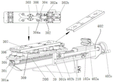
fig. 3 is a schematic structural diagram of the floating assembly and the longitudinal adjustment assembly in the embodiment of the present invention;
fig. 4 is a schematic view of a locked state of the floating assembly in an embodiment of the present invention;
fig. 5 is a schematic diagram of a floating state of a floating assembly in an embodiment of the invention;
fig. 6 is a schematic structural view of a lateral adjustment assembly in an embodiment of the present invention;
fig. 7 is a flowchart illustrating the operation of the work piece consignment apparatus according to an embodiment of the present invention.
Detailed Description
In order to make the technical means, creation features, achievement purposes and effects of the present invention easy to understand, the following description is made in conjunction with the accompanying drawings.
Fig. 1 is a schematic view of the overall structure of a work piece consignment device according to an embodiment of the present invention.
As shown in fig. 1, the workpiece carrying apparatus 100 of the present embodiment is used to lift a workpiece 200 and carry the workpiece 200 to a target position, and includes a moving mechanism 10, a holding arm 20, and an adjusting mechanism 40. In this embodiment, the workpiece 200 is a welding jig, and the lower surface of the welding jig is provided with 4 positioning pin holes.
The moving mechanism 10 includes a moving forklift 101 for horizontally moving the workpiece 200 and a lifting assembly 102 for lifting and lowering the workpiece 200.
The mobile forklift 101 includes a forklift body 101a, one steering wheel 101b, a pair of guide wheels 101c, an operation lever 101d, and a control keyboard 101 e.
The forklift body 101a has a support column 101f for mounting the lifting mast 102 a.
One steering wheel 101b is mounted on the bottom of one end of the forklift body 101a away from the traveling direction.
The pair of guide wheels 101c are each attached to the bottom of one end of the forklift body 101a in the traveling direction.
The operating lever 101d is fixedly connected to the steering wheel 101b through the steering link 101g for the user to push the moving mechanism 10, and adjusts the traveling direction of the moving mechanism 10 by adjusting the direction of the steering wheel 101 b.
The control keyboard 101e is connected to the lifting gantry 102a by a wire cable, and has a plurality of control buttons. During operation, an operator inputs a corresponding electric signal through the control button and transmits the electric signal to the driving motor in the lifting gantry 102a through the electric wire cable, so that the lifting movement of the lifting gantry 102a is controlled.
The lift assembly 102 is used to move the bolster arm 101 vertically and includes a lift gantry 102a and a bolster arm mounting plate 102 b. In other embodiments, the lift assembly 102 may also use a sprocket and sprocket arrangement or a sliding track and rail arrangement.
The supporting arm mounting plate 102b is of a frame structure with a plurality of lightening holes and is mounted on the lifting gantry 102a through a bolt connecting piece, so that the lifting gantry 102a is driven to move up and down along the vertical direction. In this embodiment, a lifting limit plate 102b-1 for limiting the vertical displacement of the support arm mounting plate 102b relative to the lifting gantry 102a is further installed on the upper portion of the support arm mounting plate 102b, and the lifting limit plate 102b-1 enables the support arm mounting plate 102b to be reliably hung on the lifting gantry 102a, so that the shear stress of the bolt connection piece between the support arm mounting plate 102b and the lifting gantry 102a is reduced, and the connection safety is improved.
Fig. 2 is a schematic structural diagram of a support arm in an embodiment of the present invention.
As shown in fig. 2, the support arm 20 is used to support a workpiece 200 and includes a first support arm 201 and a second support arm 202.
The first support arm 201 and the second support arm 202 are both mounted on the support arm mounting plate 102b through a slide rail and slider structure. In this embodiment, the upper portions of the two ends of the supporting arm mounting plate 102b are respectively provided with a lateral movement sliding rail 102c, the middle portions of the two ends of the supporting arm mounting plate 102b are respectively provided with a slot hole 102d for the supporting arm 20 to pass through and move along the length direction of the supporting arm mounting plate 102b, and the upper portions of the one ends of the first supporting arm 201 and the second supporting arm 202 are both provided with a lateral movement sliding block 102e matched with the lateral movement sliding rail 102 c. In this embodiment, the number of the lateral movement rails 102c and the lateral movement sliders 102e is two, and the two are mounted on the front surface and the rear surface of the support arm mounting plate 102b, respectively.
The first bearing arm 201 and the second bearing arm 202 are connected through a bearing arm connecting rod member 203, and the first bearing arm 201 is rotatably provided with an open gear adjusting disc 204 through a bearing.
An open gear adjusting handle 204a for rotating the connecting rod of the supporting arm is detachably mounted on the open gear adjusting disc 204.
The open-gear adjusting disc 204 has a non-cylindrical mounting recess for receiving a mounting end of the open-gear adjusting handle 204a, and the mounting end of the open-gear adjusting handle 204a has a shape corresponding to the shape of the mounting recess. In this embodiment, the sectional shapes of the open-gear adjustment handle 204a and the mounting groove are square.
A handle placing bracket 204b for placing the open gear adjusting handle 204a is also arranged on the supporting arm mounting plate 102 b.
The supporting arm connecting rod piece 203 is a telescopic lead screw assembly and is used for adjusting the distance between the first supporting arm 201 and the second supporting arm 202, and comprises an opening adjusting nut sleeve 205, an opening adjusting lead screw nut 206 and an opening adjusting lead screw 207 which are sequentially installed.
One end of the open-gear adjusting nut sleeve 205 is fixedly arranged on the open-gear adjusting disc 204, the open-gear adjusting screw nut 206 is arranged inside the other end of the open-gear adjusting nut sleeve 205, one end of the open-gear adjusting screw 207 is arranged on the open-gear adjusting screw nut 206, and the other end is fixedly arranged on the second bearing arm 202.
When the opening adjusting nut sleeve 205 is rotated, the supporting arm connecting rod 203 is made to rotate and extend (i.e. the opening adjusting screw 207 and the opening adjusting screw nut 206 move axially relatively), so that the first supporting arm 201 and the second supporting arm 202 move toward or away from each other along the length direction of the supporting arm mounting plate 102b, and the distance between the first supporting arm 201 and the second supporting arm 202 is further adjusted.
The first and second support arms 201 and 202 are each mounted with a floating assembly 30 for fine adjustment of the position of the workpiece 200 via a slide rail slider structure. In this embodiment, the first supporting arm 201 and the second supporting arm 202 are both provided with a longitudinal moving slide 208.
Fig. 3 is a schematic structural diagram of the floating assembly and the longitudinal adjustment assembly in the embodiment of the present invention.
As shown in fig. 3, the floating assembly 30 includes a mounting base plate 301, a lock switch member 302, a positioning shaft 303, a limit link 304, a spherical support 305, a floating plate 306, a positioning pin 307, a limit post 308, and a limit plate 309.
The lower portion of the mounting base plate 301 is mounted with a longitudinal movement slider 301a fitted with the longitudinal movement slide rail 208, so that the mounting base plate 301 is movably mounted on the first and second supporting arms 201 and 202. The lower portion of the other end of the mounting plate 301 is further provided with a floating stopper 301b for limiting the displacement of the floating member 30 in the longitudinal direction of the support arm 20, thereby preventing the floating member 30 from moving too much and causing the workpiece 200 to fall off the floating plate 306.
The lock switch member 302 has a moving link 302a movably mounted at one end of the mounting base plate 301 in a length direction of the mounting base plate, and a lock switch 302b for pushing the moving link 302a is mounted at one end of the moving link 302 a. In other embodiments, the locking switch 302b can be replaced by an air cylinder, and the air cylinder pushes the movable connecting rod 302a, so as to complete the locking and unlocking of the floating assembly 30.
The positioning shaft 303 is rotatably mounted on the mounting base plate 301 through a bearing, and is located at the middle of the mounting base plate 301.
The number of the limiting links 304 is two, and the limiting links are rotatably mounted on the positioning shaft 303 in an X shape, and one end of each limiting link 304 is connected with one end of the sliding link 302a through a connecting pin 304 a.
The number of the spherical supports 305 is four, and the spherical supports are respectively installed at four corners of the installation base plate 301. In this embodiment, the spherical support 305 is a gimbaled ball.
The lower surface of the floating plate 306 is in contact with the spherical surface of each spherical support 305, so that the floating plate 306 can float on the spherical support 305.
The positioning pins 307, two in number, are mounted on the upper surface of the floating plate 306 for insertion into the corresponding positioning pin holes, thereby limiting the displacement of the workpiece 200 in the horizontal direction during the consignment.
The number of the limiting columns 308 is four, one end of each limiting column is installed on the lower surface of the floating plate 306 and is respectively located at the outer sides of the two ends of the limiting connecting rod 304, and the height of each limiting column 308 is smaller than the distance between the floating plate 306 and the installation bottom plate 301.
The number of the limiting plates 309 is two, and the two limiting plates are mounted at the other ends of the two corresponding limiting columns 308 and below the limiting connecting rod 304.
Fig. 4 is a schematic diagram of a locking state of the floating assembly in the embodiment of the present invention, and fig. 5 is a schematic diagram of a floating state of the floating assembly in the embodiment of the present invention.
When the floating plate assembly is used, a user controls the floating assembly 30 to be opened or locked by pushing the movable connecting rod 302a, as shown in fig. 4, when the movable connecting rod 302a moves to the locking position, the movable connecting rod 302a drives the limiting connecting rods 304 to separate, so that the limiting connecting rods 304 are all abutted against the corresponding limiting columns 308, and the floating plate 306 is in the locking state. When in the locked state, the floating plate 306 does not float on the spherical surface of the spherical support member 305, so that displacement of the workpiece 200 in the horizontal direction is restricted by the positioning pins 307.
As shown in fig. 5, when the moving link 302a moves to the open position, the moving link 302a drives the limiting links 304 to close, so that the limiting links 304 are separated from the corresponding limiting posts 308, and the floating plate 306 is in a floating state. When in the floating state, the floating plate 306 can float on the spherical surface of the spherical support member 305, so that the operator can insert the dowel pin 307 accurately into the dowel pin hole by moving the floating plate 306.
The adjustment mechanism 40 is used to adjust the position of the bolster arm on the bolster arm mounting plate and includes a lateral adjustment assembly 401 and two longitudinal adjustment assemblies 402.
Fig. 6 is a schematic structural diagram of a lateral adjustment assembly in an embodiment of the present invention.
As shown in fig. 6, the lateral adjustment assembly 401 is used to adjust the position of the first and second support arms 201 and 202 in the lengthwise direction of the support arm mounting plate 102b and includes a lateral adjustment screw 401a, a first screw mounting block 401b, and a first screw-nut sleeve 401 c.
The lateral adjustment screw 401a extends along the length of the support arm mounting plate 102b with one end mounted to the first screw mounting block 401b and the other end being a first adjustment end mounted to the second support arm by a first screw nut sleeve 401 c. A transverse adjusting handle 401d for rotating the transverse adjusting screw 401a is detachably mounted on the first adjusting end, and an operating rod of the transverse adjusting handle 401d is of a foldable structure.
A first lead screw mount 401b is mounted on the bolster arm mounting plate 102b for limiting displacement of the lateral adjustment lead screw 401a in the length direction of the bolster arm mounting plate 102 b.
When the transverse adjusting screw 401a is rotated, the first screw nut sleeve 401c and the transverse adjusting screw 401a are displaced axially relative to each other, so that the second support arm 202 moves along the length direction of the support arm mounting plate 102b, and under the action of the support arm connecting rod 203, the first support arm 201 moves correspondingly along the length direction of the support arm mounting plate, so that the positions of the first support arm 201 and the second support arm 202 in the length direction of the support arm mounting plate 102b are adjusted.
The upper parts of the two ends of the bearing arm mounting plate 102b are provided with transverse scale scales 209 corresponding to the first bearing arm 201 and the second bearing arm 202, and the transverse scale scales are used for marking the displacement of the first bearing arm 201 and the second bearing arm 202 along the length direction of the bearing arm mounting plate 102 b.
As shown in fig. 3, the longitudinal adjusting members 402 are respectively disposed on the corresponding support arms 20 for adjusting the position of the floating member 30 in the longitudinal direction of the support arms 20, and include a longitudinal adjusting screw 402a and a second screw-nut sleeve 402 b.
A second lead screw-nut sleeve 402b is mounted on the mounting baseplate 301.
The longitudinal adjustment screw 402a extends along the length of the support arm 20 and has one end mounted to the corresponding support arm 20 and a second adjustment end mounted to the second screw nut housing 402 b. A longitudinal adjusting handle 402c for rotating the longitudinal adjusting screw rod 402a is detachably mounted on the second adjusting end, and the operating rod of the longitudinal adjusting handle 402c is of a foldable structure.
When the longitudinal adjustment screw 402a is rotated, the second screw nut set 402b is axially displaced relative to the longitudinal adjustment screw 402a to move the floating assembly 30 along the length of the support arm 20 to adjust the position of the floating assembly 30 along the length of the support arm 20.
The sides of the first and second support arms 201, 202 are provided with longitudinal graduated scales 210 corresponding to the floating assembly 30 for identifying the displacement of the floating assembly 30 along the length direction of the first and second support arms 201, 202.
Fig. 7 is a flowchart illustrating the operation of the work piece consignment apparatus according to an embodiment of the present invention.
A workpiece consignment method for consignment of the workpiece 200 by the workpiece consignment device 100 in the present embodiment will be described with reference to fig. 7, which includes the following steps:
step S1, performing initial adjustment on the support arms 20 and the floating assemblies 30, so that the two support arms 20 are symmetrical with respect to the center line of the support arm mounting plate 102b, and both the floating assemblies 30 move to the middle position of the stroke range of the floating assembly 30;
step S2, moving the workpiece carrying device 100 to the vicinity of the workpiece 200, and moving the lifting unit 102 up and down according to the height of the workpiece 200 to adjust the position of the support arm 20 in the vertical direction;
step S3, moving the workpiece carrying device 100 continuously until the support arm 20 is located right below the workpiece 200;
a step S4 of adjusting the pitch between the support arms 20 and the position in the longitudinal direction of the support arm attachment plate 102b according to the width of the workpiece 200;
step S5, adjusting the position of the floating unit 30 in the longitudinal direction of the support arm 20 according to the length of the workpiece 200;
step S6, the lifting assembly 102 continues to move upward until the supporting arm 20 supports the workpiece 200, and during the lifting process, the position of the floating assembly 30 is finely adjusted, so that the positioning pin 307 is accurately inserted into the positioning pin hole;
step S7, moving the workpiece carrying device and adjusting the positions of the supporting arm 20 and the floating assembly 30 to make the workpiece 200 be located right above the target position, allowing the lifting assembly 102 to move downward until the supporting arm 20 is separated from the workpiece 200, and fine-tuning the position of the floating assembly 30 during the lowering process to make the workpiece 200 be accurately placed at the target position.
In step S4 and step S5, the positions of the support arm 20 and the floating unit 30 are adjusted according to the positions of the positioning pins 307 and the positioning pin holes, and the position error between the positioning pins 307 and the positioning pin holes is not more than ± 5 mm.
The method for fine-tuning the position of the floating assembly 30 in step S6 includes the following sub-steps:
step S6-1, moving the moving link 302a to the open position so that the floating plate 306 is in a floating state;
step S6-2, moving the floating plate 306 so that the dowel pin 307 is inserted into the dowel pin hole;
in step S6-3, the moving link 302a is moved to the lock position so that the floating plate 306 enters the lock state.
And in the process of continuously lifting the lifting assembly 102, judging whether the positioning pin 307 is inserted into the positioning pin hole or not through the interference, if so, indicating that the positioning pin 307 is inserted into the positioning pin hole, locking the floating assembly, and if not, finely adjusting the position of the floating assembly 30 until the positioning pin 307 is inserted into the positioning pin hole.
In the process of conveying the workpiece 200 in step S7, the distance between the lowest position of the lower surface of the workpiece 200 and the ground is not less than 100 mm.
When a work piece is shipped, the floating assembly is re-locked and the work piece shipping apparatus 100 is moved to the designated station or prepared for the next shipping operation.
Examples effects and effects
According to the work piece delivery device of this embodiment, owing to have moving mechanism and bearing arm for the bearing work piece and remove the work piece to the target location, consequently the operation personnel is convenient laborsaving more to the removal of work piece when carrying out the operation, can reduce operation intensity effectively, only need alone alright accomplish the operation, and the work piece can not produce and rock in the operation process simultaneously, also is difficult for causing accidents such as dropping, has improved the security of operation. Owing to have adjustment mechanism, consequently the operation personnel need not through the manpower alright in order to adjust the position of work piece when the operation for location to the work piece is more accurate, and the efficiency of operation is higher, also lighter during the operation.
Because have telescopic bearing arm and connect member, horizontal adjusting part and vertical adjusting part, be used for adjusting the interval between two bearing arms, the bearing arm along the ascending position of the length direction of bearing arm mounting panel and the subassembly that floats along the ascending position of bearing arm length direction respectively, consequently adjustment mechanism in this embodiment has the ascending regulatory function in three side, has further improved precision and the operating efficiency to the work piece position location.
Because the bearing arm is also provided with the floating assembly, when the floating assembly is in a floating state, the position of the positioning pin can be further finely adjusted, so that an operator can more accurately insert the positioning pin into the positioning pin hole during operation, and the operation precision is further improved. In addition, when the floating assembly is in a locking state, the displacement of the workpiece in the horizontal direction can be limited, so that the workpiece is not shaken, and the safety in the operation process is improved.
Because be equipped with the scale respectively on bearing arm mounting panel and the bearing arm, consequently at operation in-process operation personnel can reduce the regulation time of bearing arm according to the more accurate location of the instruction of scale.
Because the bearing arm is connected the member, transversely adjusts the subassembly and vertically all is equipped with adjustment handle on the subassembly, consequently the operation in-process is more convenient to the position adjustment of bearing arm and subassembly that floats, and the operation is simpler.
Because the bearing arm passes the bearing arm mounting panel through the slotted hole, the mounting height of bearing arm has been reduced by a wide margin, make the upper surface of the subassembly that floats on the bearing arm be a little higher than the upper surface of bearing arm mounting panel, consequently make the operation in-process work piece can backward move fully, until leaning on the lift limiting plate who lives the bearing arm mounting panel, thereby make the focus of work piece consignment device in this embodiment move backward, the effective safe load of the work piece consignment device in this embodiment has been increased, can be applicable to the heavy work piece of large size, the security performance is stronger.
Because the workpiece consignment device in the embodiment adopts the frame structure, the bearing capacity is effectively improved while the self weight and the overall dimension are reduced, and therefore, the workpiece consignment device can meet various complex space requirements.
The foregoing has described in detail preferred embodiments of the present invention. It should be understood that numerous modifications and variations could be devised by those skilled in the art in light of the teachings of this invention without undue experimentation. Therefore, the technical solutions that can be obtained by a person skilled in the art through logic analysis, reasoning or limited experiments based on the prior art according to the concepts of the present invention should be within the scope of protection defined by the claims.
Claims (9)
1. A workpiece carrying apparatus for picking up a workpiece and carrying the workpiece to a target position, comprising:
the supporting arm is used for supporting the workpiece;
the moving mechanism is used for driving the bearing arm to move so as to move the workpiece and is provided with a bearing arm mounting plate used for mounting the bearing arm;
an adjusting mechanism for adjusting the position of the bearing arm on the bearing arm mounting plate,
wherein the bearing arm comprises a first bearing arm and a second bearing arm which are connected through a bearing arm connecting rod piece,
the adjusting mechanism is provided with a transverse adjusting component which comprises a transverse adjusting screw rod extending along the length direction of the bearing arm mounting plate, a first screw rod mounting seat and a first screw rod nut sleeve,
the first screw rod mounting seat is arranged on the bearing arm mounting plate and is used for limiting the displacement of the transverse adjusting screw rod in the length direction of the bearing arm mounting plate,
one end of the transverse adjusting screw rod is arranged on the first screw rod mounting seat,
the other end of the transverse adjusting screw rod is a first adjusting end and is arranged on the second bearing arm through the first screw rod nut sleeve,
when the transverse adjusting screw rod is rotated, the first screw rod nut sleeve and the transverse adjusting screw rod are subjected to relative axial displacement, so that the second bearing arm moves along the length direction of the bearing arm mounting plate, and under the action of the bearing arm connecting rod piece, the first bearing arm correspondingly moves along the length direction of the bearing arm mounting plate, and the positions of the first bearing arm and the second bearing arm in the length direction of the bearing arm mounting plate are adjusted.
2. The workpiece consignment device as claimed in claim 1, wherein:
wherein the first bearing arm is rotatably provided with an opening adjusting disc,
one end of the bearing arm connecting rod piece is arranged on the opening adjusting disc, the other end is arranged on the second bearing arm,
the bearing arm connecting rod piece is of a telescopic structure and is used for adjusting the distance between the first bearing arm and the second bearing arm, and comprises a gear opening adjusting nut sleeve, a gear opening adjusting screw nut and a gear opening adjusting screw rod which are sequentially arranged,
when the gear opening adjusting disc is rotated, the bearing arm connecting rod piece is made to rotate and stretch, so that the first bearing arm and the second bearing arm move in opposite directions or back to back along the length direction of the bearing arm mounting plate, and the distance between the first bearing arm and the second bearing arm is adjusted.
3. The work piece consignment device according to claim 2, wherein:
wherein the gear opening adjusting disc is detachably provided with a gear opening adjusting handle which is used for rotating the bearing arm connecting rod piece,
the gear opening adjusting disc is provided with a non-cylindrical mounting groove for inserting the mounting end of the gear opening adjusting handle,
the shape of the mounting end is adapted to the shape of the mounting groove.
4. The workpiece consignment device as claimed in claim 1, wherein:
wherein the bearing arm is provided with a floating component, the floating component comprises a mounting bottom plate movably mounted on the bearing arm and a floating plate for bearing the workpiece,
the adjusting mechanism is also provided with two longitudinal adjusting components which are respectively arranged on the corresponding bearing arms and used for adjusting the positions of the floating components in the length direction of the bearing arms,
each longitudinal adjustment assembly comprises a longitudinal adjustment screw extending along the length of the support arm and a second screw-nut sleeve,
the second feed screw nut sleeve is arranged on the mounting base plate,
one end of the longitudinal adjusting screw rod is arranged on the bearing arm,
the other end of the longitudinal adjusting screw rod is a second adjusting end and is arranged on the second screw rod nut sleeve,
when the longitudinal adjusting screw rod is rotated, the second screw rod nut sleeve and the longitudinal adjusting screw rod are subjected to relative axial displacement, so that the floating assembly moves along the length direction of the bearing arm, and the position of the floating assembly in the length direction of the bearing arm is adjusted.
5. The work piece consignment device according to claim 4, wherein:
wherein the workpiece is provided with at least one pair of positioning holes,
the float assembly further comprises:
a locking switch member having a moving link movably installed at one end of the installation base plate in a length direction of the installation base plate;
the positioning shaft is arranged on the mounting bottom plate and is positioned in the middle of the mounting bottom plate;
the two limiting connecting rods are rotatably arranged on the positioning shaft in an X shape, and one end of each limiting connecting rod is connected with one end of the movable connecting rod through a connecting pin;
four spherical support members respectively installed at four corners of the installation base plate, each having a spherical surface contacting a lower surface of the floating plate, so that the floating plate can float on the spherical support members;
a positioning pin installed on an upper surface of the floating plate for being inserted into the positioning hole, thereby limiting displacement of the workpiece in a horizontal direction during the consignment;
four limit posts which are arranged on the lower surface of the floating plate and are respectively positioned at the outer sides of the two ends of the limit connecting rod, the height of the limit posts is less than the distance between the floating plate and the installation bottom plate,
when the movable connecting rod moves to the locking position, the movable connecting rod drives the limiting connecting rods to separate, so that the limiting connecting rods are abutted against the corresponding limiting columns, the floating plate is in a locking state,
when the movable connecting rod moves to the opening position, the movable connecting rod drives the limiting connecting rods to be closed, so that the limiting connecting rods are separated from the corresponding limiting columns, and the floating plate is in a floating state.
6. The work piece consignment device according to claim 4, wherein:
wherein, the upper parts of the two ends of the bearing arm mounting plate are provided with a graduated scale corresponding to the first bearing arm and the second bearing arm,
the graduated scale is used for marking the displacement of the first bearing arm and the second bearing arm along the length direction of the bearing arm mounting plate,
the outer side surfaces of the supporting arms are respectively provided with a longitudinal scale corresponding to the floating assembly,
the longitudinal graduated scale is used for marking the displacement of the floating assembly along the length direction of the bearing arm.
7. The workpiece consignment device as claimed in claim 1, wherein:
wherein the moving mechanism comprises a moving forklift for horizontally moving the workpiece and a lifting component for lifting and lowering the workpiece,
the mobile forklift is provided with:
a forklift body having a support column for mounting the lifting assembly;
the steering wheel is arranged at the bottom of one end of the forklift body far away from the advancing direction;
the pair of guide wheels are arranged at the bottom of one end of the forklift body close to the advancing direction; and
an operation lever fixedly connected to the steering wheel through a steering connection lever for a user to push the moving mechanism and to adjust a traveling direction of the moving mechanism by adjusting a direction of the steering wheel,
the lifting assembly has a lifting mast mounted on the support column,
the supporting arm mounting plate is installed on the lifting portal.
8. The workpiece consignment device as claimed in claim 7, wherein:
wherein the forklift body is also provided with a control keyboard,
the control keyboard is connected with the lifting portal frame through a power line and is provided with a plurality of control buttons for controlling the lifting portal frame.
9. The workpiece consignment device as claimed in claim 1, wherein:
the first adjusting end of the transverse adjusting screw rod is detachably provided with a transverse adjusting handle, and the transverse adjusting handle is used for rotating the transverse adjusting screw rod.
Priority Applications (1)
| Application Number | Priority Date | Filing Date | Title |
|---|---|---|---|
| CN201920626450.XU CN210340233U (en) | 2019-05-05 | 2019-05-05 | Work piece consignment device |
Applications Claiming Priority (1)
| Application Number | Priority Date | Filing Date | Title |
|---|---|---|---|
| CN201920626450.XU CN210340233U (en) | 2019-05-05 | 2019-05-05 | Work piece consignment device |
Publications (1)
| Publication Number | Publication Date |
|---|---|
| CN210340233U true CN210340233U (en) | 2020-04-17 |
Family
ID=70181489
Family Applications (1)
| Application Number | Title | Priority Date | Filing Date |
|---|---|---|---|
| CN201920626450.XU Active CN210340233U (en) | 2019-05-05 | 2019-05-05 | Work piece consignment device |
Country Status (1)
| Country | Link |
|---|---|
| CN (1) | CN210340233U (en) |
Cited By (1)
| Publication number | Priority date | Publication date | Assignee | Title |
|---|---|---|---|---|
| CN110002363A (en) * | 2019-05-05 | 2019-07-12 | 上海宝业机电科技有限公司 | A kind of workpiece conveying device and workpiece shipping method |
-
2019
- 2019-05-05 CN CN201920626450.XU patent/CN210340233U/en active Active
Cited By (2)
| Publication number | Priority date | Publication date | Assignee | Title |
|---|---|---|---|---|
| CN110002363A (en) * | 2019-05-05 | 2019-07-12 | 上海宝业机电科技有限公司 | A kind of workpiece conveying device and workpiece shipping method |
| CN110002363B (en) * | 2019-05-05 | 2024-02-20 | 上海宝业机电科技有限公司 | Workpiece delivery device and workpiece delivery method |
Similar Documents
| Publication | Publication Date | Title |
|---|---|---|
| CN102333617B (en) | Turnover apparatus | |
| CN210709464U (en) | Full-automatic overturning material moving machine | |
| CN107486825B (en) | Work or material rest, loading attachment and automatic system of getting and putting work piece | |
| CN112917140A (en) | Elevator L board installation device | |
| CN102015205B (en) | Pallet loader and manipulator | |
| CN115502698A (en) | An automatic docking device | |
| US20240165754A1 (en) | A System and a Method for Locating a Workpiece-Holder Frame in Position in a Processing or Assembling Station of a Production Plant | |
| CN113894755B (en) | Workstation and router laser marking machine of processing angularly adjustable | |
| KR101494692B1 (en) | tool jig apparatus for machine tool | |
| CN210340233U (en) | Work piece consignment device | |
| CN219546627U (en) | An automated loading and unloading system | |
| CN217122147U (en) | Rotary feeding and discharging workbench and router laser marking machine | |
| CN215755153U (en) | Feeding and discharging mechanism based on manipulator and used for flexible bending center | |
| CN110002363B (en) | Workpiece delivery device and workpiece delivery method | |
| CN221521220U (en) | A feeding device for shaft-shaped materials | |
| CN220050705U (en) | Automatic assembling mechanism for LNG tank body and end frame | |
| CN109079501B (en) | Rail welding recovery vehicle and rail sawing machine moving device thereof | |
| CN218461373U (en) | Turnover bridge welding device | |
| CN114905294B (en) | Manipulator overturning and workpiece clamping operation platform | |
| CN114789293B (en) | An automatic feeding device for projection welding of automobile nut conveyor plates | |
| CN216575984U (en) | Steel sheet cutting machine convenient to material loading | |
| CN113213379A (en) | Lifting platform for mechanical automation production | |
| CN215846985U (en) | Machining center with adjustable | |
| CN111537369B (en) | Automated rolling test equipment | |
| CN116556633A (en) | Glass installation positioning equipment for building construction |
Legal Events
| Date | Code | Title | Description |
|---|---|---|---|
| GR01 | Patent grant | ||
| GR01 | Patent grant |