CN210298065U - Loudspeaker - Google Patents
Loudspeaker Download PDFInfo
- Publication number
- CN210298065U CN210298065U CN201921555523.7U CN201921555523U CN210298065U CN 210298065 U CN210298065 U CN 210298065U CN 201921555523 U CN201921555523 U CN 201921555523U CN 210298065 U CN210298065 U CN 210298065U
- Authority
- CN
- China
- Prior art keywords
- voice coil
- iron
- side plate
- loudspeaker
- speaker
- Prior art date
- Legal status (The legal status is an assumption and is not a legal conclusion. Google has not performed a legal analysis and makes no representation as to the accuracy of the status listed.)
- Active
Links
- XEEYBQQBJWHFJM-UHFFFAOYSA-N Iron Chemical compound [Fe] XEEYBQQBJWHFJM-UHFFFAOYSA-N 0.000 claims abstract description 72
- 229910052742 iron Inorganic materials 0.000 claims abstract description 37
- WABPQHHGFIMREM-UHFFFAOYSA-N lead(0) Chemical compound [Pb] WABPQHHGFIMREM-UHFFFAOYSA-N 0.000 claims description 12
- 239000004576 sand Substances 0.000 claims description 4
- 230000035945 sensitivity Effects 0.000 abstract description 7
- 239000000853 adhesive Substances 0.000 description 7
- 230000001070 adhesive effect Effects 0.000 description 7
- 239000004020 conductor Substances 0.000 description 6
- 238000010586 diagram Methods 0.000 description 3
- 238000000034 method Methods 0.000 description 3
- RYGMFSIKBFXOCR-UHFFFAOYSA-N Copper Chemical compound [Cu] RYGMFSIKBFXOCR-UHFFFAOYSA-N 0.000 description 2
- 238000006243 chemical reaction Methods 0.000 description 2
- 229910052802 copper Inorganic materials 0.000 description 2
- 239000010949 copper Substances 0.000 description 2
- 238000007747 plating Methods 0.000 description 2
- 229920000742 Cotton Polymers 0.000 description 1
- BQCADISMDOOEFD-UHFFFAOYSA-N Silver Chemical compound [Ag] BQCADISMDOOEFD-UHFFFAOYSA-N 0.000 description 1
- XAGFODPZIPBFFR-UHFFFAOYSA-N aluminium Chemical compound [Al] XAGFODPZIPBFFR-UHFFFAOYSA-N 0.000 description 1
- 229910052782 aluminium Inorganic materials 0.000 description 1
- 238000004891 communication Methods 0.000 description 1
- 230000008094 contradictory effect Effects 0.000 description 1
- YCKOAAUKSGOOJH-UHFFFAOYSA-N copper silver Chemical compound [Cu].[Ag].[Ag] YCKOAAUKSGOOJH-UHFFFAOYSA-N 0.000 description 1
- TVZPLCNGKSPOJA-UHFFFAOYSA-N copper zinc Chemical compound [Cu].[Zn] TVZPLCNGKSPOJA-UHFFFAOYSA-N 0.000 description 1
- 238000005516 engineering process Methods 0.000 description 1
- 239000000835 fiber Substances 0.000 description 1
- 238000003780 insertion Methods 0.000 description 1
- 230000037431 insertion Effects 0.000 description 1
- 230000005389 magnetism Effects 0.000 description 1
- 239000000463 material Substances 0.000 description 1
- 230000005855 radiation Effects 0.000 description 1
- 238000000926 separation method Methods 0.000 description 1
- 229910052709 silver Inorganic materials 0.000 description 1
- 239000004332 silver Substances 0.000 description 1
Images


Landscapes
- Audible-Bandwidth Dynamoelectric Transducers Other Than Pickups (AREA)
Abstract
The utility model provides a loudspeaker, including support, vibrating diaphragm, U iron, a plurality of magnet, a plurality of magnetic conduction board and a plurality of voice coil loudspeaker voice coil, the vibrating diaphragm is located the upper end of support, the U iron is located the lower extreme of support, the support the vibrating diaphragm with the U iron encloses to close and forms the sound chamber, the U iron towards the concave storage tank that is equipped with a plurality of intervals setting in surface of vibrating diaphragm, each magnet is installed in one in the storage tank, each the magnetic conduction board install in one in the storage tank, and each the magnetic conduction board is located one the magnet towards the surface of vibrating diaphragm, the U iron with magnet with form the magnetic gap between the magnetic conduction board, each the upper end of voice coil loudspeaker voice coil connect in the vibrating diaphragm, the lower extreme is inserted and is located in the magnetic gap. The technical scheme of the utility model the effective line length shorter problem of voice coil loudspeaker voice coil in having solved present speaker has improved the sensitivity of speaker.
Description
Technical Field
The utility model relates to a speaker technical field, in particular to speaker.
Background
With the development of the technology and the development of the electronic market, the sound quality of the acoustic devices of electronic devices such as mobile phones, tablet computers, MP3, MP4 and other electronic and communication products has higher and higher requirements, and the acoustic devices are developed towards miniaturization, thinning, high sound quality, high sensitivity and other requirements. The speaker that often uses is single voice coil list magnetic circuit speaker on the market at present, but the speaker that should set up can take place to warp easily because the restriction of space and structure sets up the voice coil loudspeaker voice coil overlength, but the effective coil length of shorter voice coil loudspeaker voice coil is short, and the magnetic circuit that corresponds is less, leads to the sensitivity of speaker to be low.
SUMMERY OF THE UTILITY MODEL
The utility model aims at providing a loudspeaker aims at solving the shorter problem of effective line length of voice coil loudspeaker voice coil in present loudspeaker to improve loudspeaker's sensitivity.
In order to achieve the above object, the present invention provides a speaker, including:
a support;
the vibrating diaphragm is arranged at the upper end of the bracket;
the U iron is arranged at the lower end of the support, the vibrating diaphragm and the U iron are enclosed to form a sound cavity, and a plurality of accommodating grooves arranged at intervals are concavely arranged on the surface of the U iron facing the vibrating diaphragm;
each magnet is arranged in one accommodating groove;
each magnetic conduction plate is arranged in one containing groove and is arranged on the surface of one magnet facing the vibrating diaphragm, and a magnetic gap is formed between the U iron and the magnet and between the U iron and the magnetic conduction plates; and
and the upper end of each voice coil is connected to the vibrating diaphragm, and the lower end of each voice coil is inserted into the magnetic gap.
The utility model discloses an in one embodiment, the storage tank the voice coil loudspeaker voice coil magnet and the magnetic conduction board all is provided with two, two the storage tank is followed the length direction interval of vibrating diaphragm sets up, two the voice coil loudspeaker voice coil is inserted respectively and is located two the magnetism clearance.
In an embodiment of the present invention, each of the voice coils includes a first side plate adjacent to the voice coil and a second side plate forming a surrounding structure with the first side plate, and the second side plate is higher than the first side plate.
The utility model discloses an in the embodiment, the second curb plate includes two straightways and an segmental arc, two the straightway connect respectively in the both ends of segmental arc, and two the straightway sets up relatively, first curb plate clamp is located two between the straightway.
In an embodiment of the present invention, the length of the straight line segment is greater than the length of the first side plate.
In an embodiment of the present invention, the two opposite ends of the support are both provided with a terminal, and each of the voice coils is electrically connected to both of the terminals.
In an embodiment of the present invention, each of the voice coil and two is provided with a silk thread between the terminals, when one end of the silk thread is electrically connected to the voice coil, the silk thread is provided with an included angle with the straight line segment of the voice coil.
In an embodiment of the present invention, the electric connection of the lead wire line is connected to the one end of the voice coil, the other end of the voice coil is electrically connected to the terminal.
In an embodiment of the present invention, the vibrating diaphragm includes a fixing portion disposed at an edge and a vibrating portion connected to the fixing portion, and a side of the fixing portion away from the vibrating portion is fixedly connected to the bracket;
the surface that vibration portion faced the voice coil loudspeaker voice coil is protruding to be equipped with annular sand grip, the voice coil loudspeaker voice coil connect in annular sand grip.
In an embodiment of the present invention, the inner wall of the lower end of the bracket is provided with an annular limiting portion, and the annular limiting portion abuts against the outer edge of the upper end of the U-shaped iron.
The utility model provides a loudspeaker, through being provided with a plurality of voice coils and having a plurality of magnet and a plurality of magnetic conduction board with this loudspeaker, each voice coil loudspeaker voice coil is installed in an accommodating tank, each accommodating tank, a voice coil loudspeaker voice coil, a magnet and a magnetic conduction board can be formed with a magnetic circuit, a plurality of accommodating tanks promptly, a plurality of voice coils loudspeaker voice coil, a plurality of magnet and a plurality of magnetic conduction board are formed with a plurality of magnetic circuits, thereby this loudspeaker is when the width is unchangeable and guarantee voice coil loudspeaker voice coil length, improve the effective line length through a plurality of voice coils, the magnetic circuit of loudspeaker has been strengthened, obtain higher magnetic field strength value, and then solved present loudspeaker and used same voice coil loudspeaker voice coil to lead to the shorter problem of.
Drawings
In order to more clearly illustrate the embodiments of the present invention or the technical solutions in the prior art, the drawings needed to be used in the description of the embodiments or the prior art will be briefly described below, it is obvious that the drawings in the following description are only some embodiments of the present invention, and for those skilled in the art, other drawings can be obtained according to the structures shown in the drawings without creative efforts.
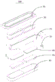
Fig. 1 is a schematic structural diagram of an embodiment of a speaker according to the present invention;
fig. 2 is an exploded view of the loudspeaker of fig. 1;
fig. 3 is a cross-sectional view of the loudspeaker of fig. 1;
FIG. 4 is an enlarged view at A in FIG. 3;
fig. 5 is a schematic structural diagram of a voice coil in the speaker of the present invention;
fig. 6 is a schematic structural diagram of a U-iron in the speaker of the present invention;
fig. 7 is a schematic structural view of the speaker of the present invention in which the magnet is mounted in the U-shaped iron;
fig. 8 is a schematic structural view of the speaker according to the present invention, wherein the voice coil is electrically connected to the terminal;
description of the reference numerals
| Reference numerals | Name (R) | Reference numerals | Name (R) |
| 100 | |
321 | |
| 10 | |
322 | Straight line segment |
| 11 | Annular limiting |
40 | |
| 20 | |
41 | Containing |
| 21 | |
42 | |
| 22 | Vibrating |
43 | |
| 221 | |
50 | |
| 30 | |
60 | Magnetic |
| 31 | |
70 | Terminal with a |
| 32 | |
80 | Lead wire |
The objects, features and advantages of the present invention will be further described with reference to the accompanying drawings.
DETAILED DESCRIPTION OF EMBODIMENT (S) OF INVENTION
The technical solutions in the embodiments of the present invention will be described clearly and completely with reference to the accompanying drawings in the embodiments of the present invention, and it is obvious that the described embodiments are only some embodiments of the present invention, not all embodiments. Based on the embodiments in the present invention, all other embodiments obtained by a person skilled in the art without creative efforts belong to the protection scope of the present invention.
It should be noted that all the directional indicators (such as upper, lower, left, right, front and rear … …) in the embodiment of the present invention are only used to explain the relative position relationship between the components, the motion situation, etc. in a specific posture (as shown in the drawings), and if the specific posture is changed, the directional indicator is changed accordingly.
In the present application, unless expressly stated or limited otherwise, the terms "connected" and "fixed" are to be construed broadly, e.g., "fixed" may be fixedly connected or detachably connected, or integrally formed; can be mechanically or electrically connected; they may be directly connected or indirectly connected through intervening media, or they may be connected internally or in any other suitable relationship, unless expressly stated otherwise. The specific meaning of the above terms in the present invention can be understood according to specific situations by those skilled in the art.
In addition, descriptions in the present application as to "first", "second", and the like are for descriptive purposes only and are not to be construed as indicating or implying relative importance or implicit to the number of technical features indicated. Thus, a feature defined as "first" or "second" may explicitly or implicitly include at least one such feature. In addition, the technical solutions in the embodiments may be combined with each other, but it must be based on the realization of those skilled in the art, and when the technical solutions are contradictory or cannot be realized, the combination of the technical solutions should not be considered to exist, and is not within the protection scope of the present invention.
The utility model provides a loudspeaker 100 aims at solving the problem that the effective line length of voice coil 30 is shorter in present loudspeaker 100 to improve loudspeaker 100's sensitivity.
Referring to fig. 1 to 8, in an embodiment of the speaker 100 of the present invention, the speaker 100 includes:
a support 10;
the vibrating diaphragm 20 is arranged at the upper end of the bracket 10;
the U iron 40 is arranged at the lower end of the support 10, the diaphragm 20 and the U iron 40 enclose to form a sound cavity, and a plurality of accommodating grooves 41 arranged at intervals are concavely arranged on the surface of the U iron 40 facing the diaphragm 20;
a plurality of magnets 50, each magnet 50 being mounted in one of the receiving grooves 41;
each magnetic conductive plate 60 is installed in one of the accommodating grooves 41, each magnetic conductive plate 60 is installed on a surface of one of the magnets 50 facing the diaphragm 20, and a magnetic gap 43 is formed between the U-shaped iron 40 and the magnet 50 and the magnetic conductive plates 60; and
and a plurality of voice coils 30, wherein the upper end of each voice coil 30 is connected to the diaphragm 20, and the lower end is inserted into the magnetic gap 43.
In this embodiment, a flange is disposed outwardly on a side of the bracket 10 away from the U-shaped iron 40, and an outer periphery of the diaphragm 20 is fixedly connected to the flange of the bracket 10.
The loudspeaker 100 is provided with two or more voice coils 30, two or more magnets 50 and two or more magnetic conductive plates 60, the magnetic conductive plates 60 can be fixed on the magnets 50 by adhesive, the voice coils 30 can be fixedly connected to the diaphragm 20 by adhesive, or the voice coils 30 and the diaphragm 20 are fixedly connected by interference fit. The shapes of the voice coil 30, the magnet 50 and the magnetic conductive plate 60 can be arranged in various ways, for example, the voice coil 30, the magnet 50 and the magnetic conductive plate 60 are arranged in various ways such as a circle, an ellipse and a runway.
The U-shaped iron 40 may also be fixed to the bracket 10 by an adhesive, or alternatively, by providing an annular fixing groove on the bracket 10, an inserting portion is convexly provided on a surface of the U-shaped iron 40 facing one side of the bracket 10, and the U-shaped iron 40 is fixedly connected to the bracket 10 by inserting the inserting portion into the annular fixing groove.
The magnets 50 are also adhered to the surface of the U-iron 40 facing the diaphragm 20 by the adhesive, and each magnetic conductive plate 60 is also adhered to one magnet 50 by the adhesive, and the side of the voice coil 30 away from the diaphragm 20 is inserted into the magnetic gap 43.
The use is that same U iron 40 installs a plurality of magnets 50 and a plurality of magnetic conduction board 60, keeps apart through dog 42 between two adjacent magnets 50 to guarantee each mutual noninterference between each magnet 50, this setting can make holistic structural strength higher, prevents that support 10 and vibrating diaphragm 20 from taking place to warp.
Therefore, can understand, the technical scheme of the utility model, through being provided with a plurality of voice coils 30 and corresponding to have a plurality of magnet 50 and a plurality of magnetic conduction board 60 with this speaker 100, each voice coil 30 is installed in a storage tank 41, each storage tank 41, a voice coil 30, a magnet 50 and a magnetic conduction board 60 can be formed with a magnetic circuit, a plurality of storage tanks 41 promptly, a plurality of voice coils 30, a plurality of magnet 50 and a plurality of magnetic conduction board 60 are formed with a plurality of magnetic circuits, thereby this speaker 100 is when the width is unchangeable and guarantee voice coil 30 length, improve the effective line length through a plurality of voice coils 30, the magnetic circuit of speaker 100 has been strengthened, obtain higher magnetic field strength value, and then solved present speaker 100 and used same voice coil 30 to lead to the shorter problem of effective line length, with the sensitivity of improving speaker 100.
The working principle of the loudspeaker 100 is as follows: when the voice coil 30 passes through the audio current, according to the ampere law, the voice coil 30 receives the force action and generates vibration with the audio current to drive the diaphragm 20 to generate radiation sound waves, so that the conversion from electric energy to mechanical energy and then to sound energy is realized; on the contrary, when the diaphragm 20 is subjected to the action of sound waves to drive the voice coil 30 to vibrate, the cutting force line of the conductor voice coil 30 in the magnetic field moves to generate corresponding induced electromotive force, so as to realize the conversion from sound energy to electric energy.
Referring to fig. 1 to 8, in an embodiment of the speaker 100 of the present invention, the accommodating groove 41, the voice coil 30, the magnet 50 and the magnetic conductive plate 60 are provided with two, the accommodating groove 41 is along the length direction interval of the vibrating diaphragm 20, two, the voice coil 30 is respectively inserted into the magnetic gap 43.
In this embodiment, a side plate of each voice coil 30 facing the adjacent voice coil 30 is a planar structure, two connecting plates connected to the side plate are also planar structures, and a connecting plate opposite to the side plate is a curved structure. Similarly, the sectional structures of the accommodating groove 41, the magnet 50 and the magnetic conductive plate 60 are the same as the sectional structure of the voice coil 30.
It can be understood that, by being provided with two accommodating grooves 41, voice coils 30, magnets 50 and magnetic conductive plates 60, the arrangement can avoid the arrangement of a plurality of voice coils 30 to cause a complex structure while increasing the effective wire length of the voice coils 30.
Referring to fig. 2, fig. 3 and fig. 5 in combination, in an embodiment of the speaker 100 of the present invention, each of the voice coils 30 includes a first side plate 31 adjacent to the voice coil 30 and a second side plate 32 forming an enclosing structure with the first side plate 31, and the second side plate 32 is higher than the first side plate 31.
In this embodiment, the first side plate 31 and the second side plate 32 form a track-type voice coil 30, and the height of the first side plate 31 may be half of that of the second side plate 32, and of course, the height ratio of the first side plate 31 to the second side plate 32 may be determined according to actual situations.
As can be understood, because the middle carcass portion of the diaphragm 20 is an inward concave structure, the second side plate 32 is higher than the first side plate 31, so that the carcass portion of the diaphragm 20 can be effectively avoided, and the vibration space of the diaphragm 20 is increased.
Referring to fig. 2, fig. 3, fig. 5 and fig. 6, in an embodiment of the speaker 100 of the present invention, the second side plate 32 includes two straight segments 322 and an arc-shaped segment 321, the two straight segments 322 are respectively connected to two ends of the arc-shaped segment 321, and the two straight segments 322 are disposed oppositely, and the first side plate 31 is sandwiched between the two straight segments 322.
In this embodiment, the two straight segments 322 are disposed in parallel at intervals, and the two straight segments 322 are smoothly connected to the arc-shaped segment 321.
It can be understood that the voice coil 30 is enclosed by the first side plate 31 and the second side plate 32, wherein the second side plate 32 includes two straight sections 322 and an arc-shaped section 321, and the two straight sections 322 are arranged in parallel and spaced apart, which can further increase the effective wire length of the voice coil 30 under the condition of limited internal space of the speaker 100.
Referring to fig. 2, fig. 3, fig. 5 and fig. 6, in an embodiment of the speaker 100 of the present invention, the length of the straight section 322 is greater than the length of the first side plate 31.
In this embodiment, the cross-sectional structures of the accommodating groove 41, the magnet 50 and the magnetic conductive plate 60 are all the same as the cross-sectional structure of the voice coil 50.
It can be understood that, due to the limitation of the internal space and structure of the speaker 100, by making the length of the straight line section 322 of the voice coil 30 greater than the length of the first side plate 31, the effective line length of the voice coil 30 can be increased as much as possible in the limited space, the magnetic circuit of the speaker 100 is enlarged, a higher magnetic field strength value is obtained, and the sensitivity of the speaker 100 is further effectively improved.
Referring to fig. 1 to fig. 4 and fig. 8, in an embodiment of the speaker 100 of the present invention, two opposite ends of the support 10 are respectively provided with a terminal 70, and each of the voice coils 30 is electrically connected to two of the terminals 70.
In this embodiment, the two voice coils 30 and the two terminals 70 may form a parallel circuit or a series circuit. In the case of a parallel circuit, both ends of each voice coil 30 are electrically connected to both terminals 70 directly; in the case of a series circuit, one end of each voice coil 30 is electrically connected to a terminal 70, and each voice coil 30 is electrically connected to an adjacent voice coil 30.
The outer side wall of the bracket 10 is provided with a slot, and one end of the terminal 70 is provided with an insertion portion, which is inserted into the slot to fixedly connect the terminal 70 to the bracket 10.
The side of the terminal 70 facing away from the holder 10 is provided with a socket through which an electrical connection with an external conductor is made. The material of the terminal 70 may be selected from copper silver plating, copper zinc plating, copper, aluminum, iron, and the like.
It will be appreciated that the electrical connection of the voice coil 30 to the external conductor is facilitated by connecting terminals 70 to the outer side wall of the support 10, and electrically connecting the voice coil 30 to the external conductor through the terminals 70.
Referring to fig. 8, in an embodiment of the speaker 100 of the present invention, each of the voice coil 30 and the two terminals 70 is provided with a silk thread 80 therebetween, and when one end of the silk thread 80 is electrically connected to the voice coil 30, the silk thread 80 and the straight line section 322 of the voice coil 30 form an included angle.
In this embodiment, the lead wire 80 is composed of a copper conductor or a silver conductor and a central fiber.
The silk thread 80 may be adhered to the terminal 70 and the voice coil 30 by an adhesive, or the silk thread 80 may be wound around the terminal 70 and the voice coil 30, so that the silk thread 80 is electrically connected to the terminal 70 and the voice coil 30.
It can be understood that, by using the lead wire 80 to electrically connect the voice coil 30 and the terminal 70, because the lead wire 80 has better flexibility, conductivity and other properties, the diaphragm 20 and the voice coil 30 can have enough vibration space in the vibration process, so as to ensure the sound quality of the speaker 100; because certain vibration amplitude can take place for voice coil 30 in the course of the work, therefore the length direction of lead wire line 80 and voice coil 30 can not be on same horizontal line, need to be with lead wire line 80 and the length direction of voice coil 30 to be the contained angle setting promptly.
Of course, in other embodiments of the present invention, other conductive wires with better flexibility and better conductivity may also be electrically connected to the terminal 70 and the voice coil 30, and similarly, the arrangement may also enable the diaphragm 20 and the voice coil 30 to have sufficient vibration space during the vibration process, so as to ensure the sound quality of the speaker 100.
Referring to fig. 8, in an embodiment of the speaker 100 of the present invention, the electric connection of the lead wire 80 is connected to the connection between the straight section 322 and the arc section 321 at one end of the voice coil 30, and the other end is electrically connected to the terminal 70.
In this embodiment, the connection portion of the straight line section 322 and the arc-shaped section 321 is a smooth surface, and the silk thread line 80 is connected to the straight line section 322 and located on the smooth surface.
It will be appreciated that this arrangement is effective to ensure vibration balance of the voice coil 30 by connecting one end of the cotton wire 80 electrically connected to the voice coil 30 to the junction of the straight section 322 and the curved section 321.
Referring to fig. 1 to 4, in an embodiment of the speaker 100 of the present invention, the diaphragm 20 includes a fixing portion 21 disposed at an edge and a vibrating portion 22 connected to the fixing portion 21, and a side of the fixing portion 21 away from the vibrating portion 22 is fixedly connected to the bracket 10;
the surface of the vibration part 22 facing the voice coil 30 is convexly provided with an annular convex strip 221, and the voice coil 30 is connected to the annular convex strip 221.
In this embodiment, the diaphragm 20 may be a substantially body structure with a downward-depressed middle portion, the annular protrusion 221 is disposed on a side of the vibrating portion 22 close to the fixing portion 21 relative to the central position, and the voice coil 30 may be fixedly connected to the vibrating portion 22 by means of adhesive.
It can be understood that, by fixedly connecting the voice coil 30 to the annular protruding strip 221, the contact area of the connection between the voice coil 30 and the diaphragm 20 can be effectively increased, the firmness of the connection between the voice coil 30 and the diaphragm 20 is increased, and the separation of the voice coil 30 from the diaphragm 20 in the vibration process of the loudspeaker 100 is avoided.
Referring to fig. 1 to 4, in an embodiment of the speaker 100 of the present invention, an annular limiting portion 11 is protruded from an inner wall of a lower end of the bracket 10, and the annular limiting portion 11 abuts against an outer edge of an upper end of the U-shaped iron 40.
In this embodiment, when the U-shaped iron 40 is covered on the bracket 10, the outer side wall of the U-shaped iron 40 abuts against the inner surface of the bracket 10, and the annular limiting portion 11 abuts against the outer edge of the upper end of the U-shaped iron 40.
It can be understood that, by providing the annular limiting portion 11 on the inner wall of the diaphragm 20, when the U-shaped iron 40 is disposed on the support 10, it is ensured that the diaphragm 20 and the voice coil 30 have a certain vibration space in the support 10, and the U-shaped iron 40 is convenient to be fixedly mounted on the support 10.
The above only be the preferred embodiment of the utility model discloses a not consequently restriction the utility model discloses a patent range, all are in the utility model discloses a conceive, utilize the equivalent structure transform of what the content was done in the description and the attached drawing, or direct/indirect application all is included in other relevant technical field the utility model discloses a patent protection within range.
Claims (10)
1. A loudspeaker, comprising:
a support;
the vibrating diaphragm is arranged at the upper end of the bracket;
the U iron is arranged at the lower end of the support, the vibrating diaphragm and the U iron are enclosed to form a sound cavity, and a plurality of accommodating grooves arranged at intervals are concavely arranged on the surface of the U iron facing the vibrating diaphragm;
each magnet is arranged in one accommodating groove;
each magnetic conduction plate is arranged in one containing groove and is arranged on the surface of one magnet facing the vibrating diaphragm, and a magnetic gap is formed between the U iron and the magnet and between the U iron and the magnetic conduction plates; and
and the upper end of each voice coil is connected to the vibrating diaphragm, and the lower end of each voice coil is inserted into the magnetic gap.
2. The loudspeaker according to claim 1, wherein there are two of the receiving grooves, the voice coils, the magnets and the magnetic conductive plates, two of the receiving grooves are spaced apart along a length direction of the diaphragm, and two of the voice coils are respectively inserted into two of the magnetic gaps.
3. The speaker of claim 2, wherein each of the voice coils comprises a first side plate adjacent to the voice coil and a second side plate forming a surrounding structure with the first side plate, the second side plate being higher than the first side plate.
4. The speaker of claim 3, wherein the second side plate comprises two straight segments and an arc segment, the two straight segments are respectively connected to two ends of the arc segment, the two straight segments are oppositely disposed, and the first side plate is sandwiched between the two straight segments.
5. The loudspeaker of claim 4 wherein the length of the straight segment is greater than the length of the first side panel.
6. A loudspeaker according to claim 5, wherein the support has a terminal at each of opposite ends thereof, and each of the voice coils is electrically connected to both of the terminals.
7. The speaker of claim 6, wherein a lead wire is disposed between each voice coil and the two terminals, and when one end of the lead wire is electrically connected to the voice coil, the lead wire forms an included angle with a straight line section of the voice coil.
8. The speaker of claim 7, wherein one end of the lead wire electrically connected to the voice coil is connected to the connection of the straight section and the arc section, and the other end is electrically connected to the terminal.
9. The loudspeaker according to any one of claims 1 to 8, wherein the diaphragm comprises a fixing portion provided at an edge and a vibrating portion connected to the fixing portion, and a side of the fixing portion away from the vibrating portion is fixedly connected to the bracket;
the surface that vibration portion faced the voice coil loudspeaker voice coil is protruding to be equipped with annular sand grip, the voice coil loudspeaker voice coil connect in annular sand grip.
10. The loudspeaker according to any one of claims 1 to 8, wherein an annular limiting part is convexly arranged on the inner wall of the lower end of the bracket, and the annular limiting part is abutted with the outer edge of the upper end of the U-shaped iron.
Priority Applications (1)
| Application Number | Priority Date | Filing Date | Title |
|---|---|---|---|
| CN201921555523.7U CN210298065U (en) | 2019-09-18 | 2019-09-18 | Loudspeaker |
Applications Claiming Priority (1)
| Application Number | Priority Date | Filing Date | Title |
|---|---|---|---|
| CN201921555523.7U CN210298065U (en) | 2019-09-18 | 2019-09-18 | Loudspeaker |
Publications (1)
| Publication Number | Publication Date |
|---|---|
| CN210298065U true CN210298065U (en) | 2020-04-10 |
Family
ID=70063391
Family Applications (1)
| Application Number | Title | Priority Date | Filing Date |
|---|---|---|---|
| CN201921555523.7U Active CN210298065U (en) | 2019-09-18 | 2019-09-18 | Loudspeaker |
Country Status (1)
| Country | Link |
|---|---|
| CN (1) | CN210298065U (en) |
Cited By (1)
| Publication number | Priority date | Publication date | Assignee | Title |
|---|---|---|---|---|
| CN111970618A (en) * | 2020-10-20 | 2020-11-20 | 歌尔股份有限公司 | Sound generating device and wearable equipment |
-
2019
- 2019-09-18 CN CN201921555523.7U patent/CN210298065U/en active Active
Cited By (2)
| Publication number | Priority date | Publication date | Assignee | Title |
|---|---|---|---|---|
| CN111970618A (en) * | 2020-10-20 | 2020-11-20 | 歌尔股份有限公司 | Sound generating device and wearable equipment |
| CN111970618B (en) * | 2020-10-20 | 2021-01-22 | 歌尔股份有限公司 | Sound generating device and wearable equipment |
Similar Documents
| Publication | Publication Date | Title |
|---|---|---|
| CN216775018U (en) | Loudspeaker and sound production device | |
| CN110366080B (en) | Speaker and audio device | |
| CN113099362B (en) | Sound producing device | |
| CN110418257B (en) | Sound producing device | |
| CN108632729A (en) | Microphone device and portable terminal | |
| US10764688B2 (en) | Speaker | |
| CN217470269U (en) | Sound production device and audio equipment | |
| CN216775013U (en) | Speaker and sound generating apparatus | |
| CN214381372U (en) | Speaker and electronic apparatus | |
| CN113473330A (en) | Speaker and electronic apparatus | |
| CN214381371U (en) | Speaker and electronic apparatus | |
| CN117202042A (en) | Micro-speaker and acoustic device | |
| CN110418259B (en) | Sound production device monomer, sound production module and electronic terminal | |
| CN119402798B (en) | Sound generator and electronic devices | |
| US8855354B2 (en) | Electroacoustic transducer with wireless charging coil | |
| CN216775012U (en) | Speaker and sound generating apparatus | |
| CN114257926B (en) | Sound producing device and electronic equipment | |
| CN117221798A (en) | Micro-speaker and acoustic device | |
| CN119562194A (en) | Sound generating devices and electronic equipment | |
| CN210298065U (en) | Loudspeaker | |
| CN111050253B (en) | Exciter and electronic product | |
| CN216775023U (en) | Loudspeaker and sound production device | |
| CN207783130U (en) | Loud speaker and earphone | |
| US9820066B2 (en) | Micro speaker with capacitors formed by conductive cover and diaphragm | |
| CN109743662B (en) | Centering support piece and sound production device |
Legal Events
| Date | Code | Title | Description |
|---|---|---|---|
| GR01 | Patent grant | ||
| GR01 | Patent grant |