SUMMERY OF THE UTILITY MODEL
The utility model aims at providing an easily remove trailer formula horizontal directional drilling machine of supplementary mobile device in area.
According to one aspect of the utility model, a trailer type horizontal directional drilling machine with an auxiliary moving device is provided, which comprises a machine head, a machine body, a supporting mechanism, a tug, a first supporting leg, a second supporting leg, a first translation mechanism and a second translation mechanism,
the headstock is rotatably connected with the machine body through a pin shaft, a tug is arranged at the bottom of the machine body, a support mechanism is arranged at one end part of the machine body connected with the headstock, a first support leg is arranged at the other end part of the machine body, a first translation mechanism is arranged at the end part of the first support leg, a second support leg is arranged at the bottom of the machine body, a second translation mechanism is arranged at the end part of the second support leg,
the first supporting leg and the second supporting leg are put down, the first translation mechanism and the second translation mechanism are grounded, the tug and the supporting mechanism are lifted off, the first translation mechanism and the second translation mechanism move towards the same direction together to drive the machine body to move towards the direction,
and putting down the first support leg, landing the first translation mechanism, lifting the second translation mechanism, the tug and the support mechanism off the ground, and continuously moving the first translation mechanism towards the same direction to drive the body to adjust the direction by taking the connection point of the body and the head as the center of a circle.
In some embodiments, the first translation mechanism includes a first chassis, a first sliding plate, and a first oil cylinder, a cylinder body of the first oil cylinder is connected with the first chassis, a piston rod of the first oil cylinder is connected with the first sliding plate, the first sliding plate is attached to the first chassis, two opposite sides of the first chassis are provided with guide rails, two opposite sides of the first sliding plate are clamped in the guide rails,
the second translation mechanism comprises a second underframe, a second sliding plate and a second oil cylinder, wherein the cylinder body of the second oil cylinder is connected with the second underframe, the piston rod of the second oil cylinder is connected with the second sliding plate, the second sliding plate is attached to the second underframe, guide rails are arranged on two opposite sides of the second underframe, and two opposite sides of the second sliding plate are clamped in the guide rails.
In some embodiments, the first support leg comprises a first support cylinder, a cylinder body of the first support cylinder is connected with the bottom of the body, a piston rod of the first support cylinder is connected with the first sliding plate,
the second supporting legs comprise two second supporting oil cylinders, the cylinder bodies of the second supporting oil cylinders are connected with the bottom of the machine body, and piston rods of the second supporting oil cylinders are connected with the second sliding plate.
In some embodiments, the first support leg and the second support leg are put down, the first translation mechanism and the second translation mechanism are grounded, the tug and the support mechanism are lifted off, the piston rod of the first oil cylinder extends to drive the first sliding plate and the second underframe to move relatively, the second piston rod of the second oil cylinder extends to drive the second sliding plate and the second underframe to move relatively, and the machine body connected with the first sliding plate and the second sliding plate moves along with the first sliding plate and the second sliding plate,
retracting the first support leg and the second support leg, lifting the first translation mechanism and the second translation mechanism off the ground, grounding the tug and the support mechanism, driving the underframe and the sliding plate to relatively move and return to an original state by retracting the piston rod of the first oil cylinder, driving the underframe and the sliding plate to relatively move and return to a state in which the piston rod is completely retracted by retracting the piston rod of the second oil cylinder,
the recirculating motion effects a positional shift of the fuselage.
In some embodiments, the first support leg and the second support leg are retracted, the first translation mechanism and the second translation mechanism are lifted off, the tug and the support mechanism are grounded, the piston rod of the first oil cylinder extends to drive the second chassis and the first sliding plate to move relatively, the piston rod of the second oil cylinder extends to drive the second chassis to move relatively to the second sliding plate,
the first supporting leg and the second supporting leg are put down, the first translation mechanism and the second translation mechanism are grounded, the tug and the supporting mechanism are lifted off, the piston rod of the first oil cylinder retracts to drive the sliding plate and the underframe to move relatively and return to the original state, the machine body connected with the sliding plate moves along with the sliding plate, the piston rod of the second oil cylinder retracts to drive the underframe and the sliding plate to move relatively and return to the state that the piston rod retracts completely, and the machine body connected with the sliding plate moves along with the sliding plate,
the recirculating motion effects a positional shift of the fuselage.
In some embodiments, the first support leg is lowered to ground the first translation mechanism and lift the tug and the support mechanism off the ground, the piston rod of the first oil cylinder extends to drive the first sliding plate and the first underframe to move relatively, and the machine body connected with the first sliding plate moves along with the first sliding plate,
retracting the first support leg, lifting the first translation mechanism off the ground, grounding the tug and the support mechanism, retracting a piston rod of the first oil cylinder to drive the first underframe and the first sliding plate to move relatively until the piston rod is completely retracted,
the direction of the machine body is adjusted by taking a connecting point of the machine body and the vehicle head as a circle center through the recycling motion.
In some embodiments, the end of the fuselage near the second support leg is connected with a locomotive,
the first support leg is retracted, the first translation mechanism is lifted off the ground, the tug and the support mechanism are grounded, and a piston rod of the first oil cylinder extends out to drive the underframe and the sliding plate to move relatively
The first support leg is put down, the first translation mechanism is grounded, the tug and the support mechanism are lifted off, the piston rod of the first oil cylinder retracts to drive the first sliding plate and the first underframe to move relatively until the piston rod retracts completely, and the machine body connected with the first sliding plate moves along with the first sliding plate,
the direction of the machine body is adjusted by taking a connecting point of the machine body and the vehicle head as a circle center through the recycling motion.
The beneficial effects are as follows: the utility model can realize the adjustment of the position of the drill body within a small range under the condition that the horizontal directional drill is not connected with the drill head; the adjustment of the direction of the machine body can be realized in a limited space under the condition that the machine body is long.
Detailed Description
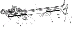
Fig. 1-4 schematically show a trailer-type horizontal directional drilling machine with an auxiliary moving device according to an embodiment of the invention. As shown in fig. 1 to 4, the trailer-type horizontal directional drilling machine with the auxiliary moving device comprises a head 8, a body 1, a support mechanism 3, a tug 2, a first support leg 4, a second support leg 5, a first translation mechanism 6 and a second translation mechanism 7.
The headstock 8 is rotatably connected with the machine body 1 through a pin shaft. The bottom of the machine body 1 is provided with a tug 2. A supporting mechanism 3 is arranged at one end part of the machine body 1 connected with the vehicle head 8. The other end of the machine body 1 is provided with a first supporting leg 4, and the end of the first supporting leg 4 is provided with a first translation mechanism 6. The bottom of fuselage 1 is equipped with second supporting leg 5, and the tip of second supporting leg 5 is equipped with second translation mechanism 7. The first supporting leg 4 and the second supporting leg 5 are put down, the first translation mechanism 6 and the second translation mechanism 7 are grounded, the tug 2 and the supporting mechanism 3 are lifted off, and the first translation mechanism 6 and the second translation mechanism 7 move towards the same direction together to drive the machine body 1 to move towards the direction. The first support leg 4 is put down, the first translation mechanism 6 is grounded, the second translation mechanism 7, the tug 2 and the support mechanism 3 are lifted off, the first translation mechanism 6 continuously moves towards the same direction, and the machine body 1 is driven to adjust the direction by taking the connection point of the machine body and the vehicle head 8 as the circle center.
The first translation mechanism 6 includes a first base frame 61, a first slide plate 62, and a first cylinder 63. The cylinder body 631 of the first cylinder 63 is connected to the first chassis 61. The piston rod 632 of the first cylinder 63 is connected to the first slide plate 62. The first sliding plate 62 is attached to the first chassis 61. The first chassis 61 is provided at opposite sides thereof with first guide rails 611. Opposite sides of the first sliding plate 62 are caught in the first guide rail 611. The first sliding plate 62 is connected to the end of the first support leg 4. The second translation mechanism 7 has the same structure as the first translation mechanism 6. The second translation mechanism 7 includes a second base frame 71, a second slide plate 72, and a second cylinder 73. The cylinder 731 of the second cylinder 73 is connected to the second chassis 71. The second piston rod 732 of the second cylinder 73 is connected to the second slide plate 72. The second sliding plate 72 is attached to the second chassis 71. The second chassis 71 is provided with second guide rails 711 on opposite sides thereof. Opposite sides of the second sliding plate 72 are caught in the second guide rail 711. The second sliding plate 72 is connected to the end of the second support leg 5. The first supporting leg 4 is adjustably mounted on the fuselage 1, and the height of the first supporting leg 4 relative to the fuselage 1 can be adjusted according to actual needs. Specifically, the first support leg 4 includes a first support cylinder, a cylinder body of the first support cylinder is connected to the bottom of the body 1, and a piston rod of the first support cylinder is connected to the first sliding plate 62. The second supporting leg 5 is adjustably arranged on the machine body 1, and the height of the second supporting leg 5 relative to the machine body 1 can be adjusted according to actual needs. Specifically, the second support leg 5 includes two second support cylinders, the cylinder bodies of the second support cylinders are rotatably connected to the bottom of the body 1, and the piston rods of the second support cylinders are connected to the second sliding plate 72. The supporting mechanism 3 is adjustably arranged on the machine body 1, and the height of the supporting mechanism relative to the machine body 1 can be adjusted according to actual needs.
The utility model discloses at the directional rig of level under the condition of not connecting the locomotive, can realize that the position of rig fuselage 1 adjusts at the minizone. The method specifically comprises the following steps: the first support leg 4 and the second support leg 5 are lowered, the first chassis 61 of the first translation mechanism 6 and the second chassis 71 of the second translation mechanism 7 are grounded, and the tug 2 and the support mechanism 3 are lifted off. The piston rod 632 of the first cylinder 63 and the piston rod 732 of the second cylinder 73 extend simultaneously to drive the first sliding plate 62 to move relative to the first chassis 61 and the second sliding plate 72 to move relative to the second chassis 71, and the first sliding plate 62 and the second sliding plate 72 are connected to the body 1, thereby realizing the movement of the position of the body 1. The first support leg 4 and the second support leg 5 are retracted to lift the first chassis 61 and the second chassis 71 off the ground, and the tug 2 and the support mechanism 3 are grounded. The piston rod 632 of the first oil cylinder 63 and the piston rod 732 of the second oil cylinder 73 retract simultaneously, the cylinder body 631 of the first oil cylinder 63 drives the first chassis 61 to move relative to the first sliding plate 62 until the first piston rod 631 retracts completely, the cylinder body 731 of the second oil cylinder 73 drives the second chassis 71 to move relative to the second sliding plate 72 until the second piston rod 732 retracts completely, and the above-mentioned actions are repeated, so that the small-range movement of the main body 1 can be realized through circulation.
The following implementations are also possible: the first support leg 4 and the second support leg 5 are retracted, the first chassis 61 of the first translation mechanism 6 and the second chassis 71 of the second translation mechanism 7 are lifted off, and the tug 2 and the support mechanism 3 are grounded. The piston rod 632 of the first cylinder 63 and the piston rod 732 of the second cylinder 73 extend simultaneously, which drives the first chassis 61 to move relative to the first sliding plate 62 and the second chassis 71 to move relative to the second sliding plate 72. The first support leg 4 and the second support leg 5 are lowered to bring the first chassis 61 and the second chassis 71 to the ground, and the tug 2 and the support mechanism 3 are lifted off the ground. The piston rod 632 of the first oil cylinder 63 and the piston rod 732 of the second oil cylinder 73 retract simultaneously, the cylinder body 631 of the first oil cylinder 63 drives the first sliding plate 62 to move relative to the first chassis 61 until the first piston rod 631 retracts completely, the cylinder body 731 of the second oil cylinder 73 drives the second sliding plate 72 to move relative to the second chassis 71 until the second piston rod 732 retracts completely, the position of the main body 1 connected with the first sliding plate 62 and the second sliding plate 72 moves accordingly, and the above actions are repeated to realize the small-range movement of the main body 1 in a circulating manner.
The utility model discloses under the longer condition of fuselage 1, in the limited space, realize the adjustment of 1 direction of fuselage. The method specifically comprises the following steps: the end part of the machine body 1 close to the second supporting leg 5 is connected with the vehicle head 8, the first supporting leg 4 is put down, the first chassis 61 of the first translation mechanism 6 is grounded, the tug 2 and the supporting mechanism 3 are lifted off, the first piston rod 631 of the first oil cylinder 63 extends out to drive the first sliding plate 62 to move relative to the first chassis 61, and the machine body 1 connected with the first sliding plate 62 moves relative to the first chassis 61 along with the first sliding plate 62, so that the position movement of the machine body 1 is realized. The first support leg is retracted, the first chassis 61 of the first translation mechanism 6 is lifted off, the tug 2 and the support mechanism 3 are grounded, the first piston rod 632 of the first oil cylinder 63 retracts, the first cylinder body 632 of the first oil cylinder 63 drives the first chassis 61 to move relative to the first sliding plate 62 until the first piston rod 632 completely retracts, the action of the previous step is repeated, the rotation of the body 1 around the connection point of the body 1 and the vehicle head 8 is realized in a circulating mode, and therefore when the vehicle head 8 changes the direction, the adjustment of the body 1 in the direction is realized.
The following implementations are also possible: the end part of the body 1 which is not provided with the first supporting leg 4 is connected with the vehicle head 8. The first support leg 4 is retracted, the first chassis 61 of the first translation mechanism 6 is lifted off the ground, the tug 2 and the support mechanism 3 are grounded, and the first piston rod 631 of the first cylinder 63 extends to drive the first chassis 61 and the first sliding plate 62 to move relatively. The first support leg is put down, the first chassis 61 of the first translation mechanism 6 is landed, the tug 2 and the support mechanism 3 are lifted off, the piston rod 632 of the first oil cylinder 63 retracts, the first cylinder body 632 of the first oil cylinder 63 drives the first sliding plate 62 to move relative to the first chassis 61 until the first piston rod 632 completely retracts, the machine body 1 connected with the first sliding plate 62 moves along with the first piston rod, the position is moved, the action of the previous step is repeated, the rotation of the machine body 1 around the connection point of the machine body 1 and the vehicle head 8 is realized in a circulating mode, and therefore when the vehicle head 8 changes the direction, the adjustment of the machine body 1 in the direction is realized.
The above are only some embodiments of the present invention. For those skilled in the art, without departing from the inventive concept, several modifications and improvements can be made, which all fall within the scope of the invention.