CN209980958U - Reactor and application device thereof - Google Patents
Reactor and application device thereof Download PDFInfo
- Publication number
- CN209980958U CN209980958U CN201920512563.7U CN201920512563U CN209980958U CN 209980958 U CN209980958 U CN 209980958U CN 201920512563 U CN201920512563 U CN 201920512563U CN 209980958 U CN209980958 U CN 209980958U
- Authority
- CN
- China
- Prior art keywords
- coil
- reactor
- potting
- magnetic core
- height
- Prior art date
- Legal status (The legal status is an assumption and is not a legal conclusion. Google has not performed a legal analysis and makes no representation as to the accuracy of the status listed.)
- Active
Links
Images


Landscapes
- Insulating Of Coils (AREA)
Abstract
本实用新型提供的电抗器及其应用装置,包括:磁芯、线圈、绝缘纸、灌封胶以及外壳;其中:所述线圈绕制于所述磁芯上;所述磁芯和所述线圈通过半灌封技术,被所述灌封胶灌封于所述外壳内;所述绝缘纸设置于所述线圈的裸露部分上,实现所述线圈与外部机箱之间的绝缘,使所述外壳的高度高于所述线圈并低于预设高度。本实用新型通过在线圈的裸露部分与机箱之间设置绝缘纸,实现半灌封技术下线圈与机箱之间的绝缘,使外壳的高度仅高于线圈即可,而低于一个预设高度,进而能够在半灌封方案保证电气绝缘的基础上,减少灌封胶用量,减小外壳的高度,解决了现有技术中重量大、成本高以及体积大的问题。
The reactor and its application device provided by the utility model include: a magnetic core, a coil, insulating paper, potting glue and a casing; wherein: the coil is wound on the magnetic core; the magnetic core and the coil Through the semi-potting technology, the potting glue is used to encapsulate the outer casing; the insulating paper is arranged on the exposed part of the coil to realize the insulation between the coil and the external chassis, so that the outer casing can be insulated. is higher than the coil and lower than the preset height. The utility model realizes the insulation between the coil and the case under the semi-potting technology by arranging insulating paper between the exposed part of the coil and the case, so that the height of the case is only higher than the coil, but lower than a preset height, Furthermore, on the basis of ensuring electrical insulation in the semi-potting solution, the amount of potting glue and the height of the casing can be reduced, thereby solving the problems of heavy weight, high cost and large volume in the prior art.
Description
技术领域technical field
本实用新型涉及电力电子技术领域,特别涉及一种电抗器及其应用装置。The utility model relates to the technical field of power electronics, in particular to a reactor and an application device thereof.
背景技术Background technique
传统的灌封式电抗器通常采用完全灌封的方法,如图1a所示,将磁芯101和漆包线绕制后的线圈102放在铝质外壳103内,通过在外壳103内灌封导热硅胶,起到散热及电气绝缘的作用,最后将灌封后的电抗器安装在整机机箱外。The traditional potting type reactor usually adopts the method of complete potting. As shown in FIG. 1a, the
为了保证线圈102和机箱之间的绝缘,外壳103的高度需要高于磁芯101和线圈102的高度,进而保证灌封后线圈102能够完全埋入导热硅胶内,即灌封胶面104以下;同时,实际工作时,电抗器产生的热量会使灌封的导热硅胶受热膨胀,因此外壳103的高度还需要高于导热硅胶的高度。In order to ensure the insulation between the
由于图1a这种全灌封方案在灌封时的导热硅胶用量较大,成本较高,电抗器重量也较大;因此,现有技术中还存在一种半灌封方案,如图1b所示,其线圈202裸露,与空气直接接触;但为了保证线圈202和机箱的电气绝缘,其外壳203的高度比全灌封方案中的外壳高度还要高,导致外壳203的重量增加;也就是说,虽然半灌封方案减少了导热硅胶的用量,但电抗器整体的重量及成本下降不明显,而且电抗器的体积也会增大,不利于应用。Since the full potting solution as shown in Fig. 1a uses a large amount of thermally conductive silica gel during potting, the cost is higher, and the weight of the reactor is also larger; therefore, there is also a semi-potting solution in the prior art, as shown in Fig. 1b It is shown that the
实用新型内容Utility model content
本实用新型提供一种电抗器及其应用装置,以解决现有技术中重量大、成本高以及体积大的问题。The utility model provides a reactor and an application device thereof to solve the problems of heavy weight, high cost and large volume in the prior art.
为实现上述目的,本申请提供的技术方案如下:To achieve the above purpose, the technical solutions provided by the application are as follows:
本实用新型一方面提供一种电抗器,包括:磁芯、线圈、绝缘纸、灌封胶以及外壳;其中:One aspect of the present utility model provides a reactor, comprising: a magnetic core, a coil, insulating paper, potting glue and a casing; wherein:
所述线圈绕制于所述磁芯上;the coil is wound on the magnetic core;
所述磁芯和所述线圈通过半灌封技术,被所述灌封胶灌封于所述外壳内;The magnetic core and the coil are encapsulated in the casing by the encapsulating glue through a semi-encapsulation technique;
所述绝缘纸设置于所述线圈的裸露部分上,实现所述线圈与外部机箱之间的绝缘,使所述外壳的高度高于所述线圈并低于预设高度。The insulating paper is arranged on the exposed part of the coil to achieve insulation between the coil and the external chassis, so that the height of the casing is higher than the coil and lower than a preset height.
优选的,所述灌封胶完全盖住所述磁芯。Preferably, the potting glue completely covers the magnetic core.
优选的,所述绝缘纸完全覆盖所述线圈朝向外部机箱的一面。Preferably, the insulating paper completely covers the side of the coil facing the external chassis.
优选的,所述外壳的高度满足所述电抗器的散热要求。Preferably, the height of the casing meets the heat dissipation requirements of the reactor.
优选的,所述绝缘纸的厚度满足所述电抗器接收电压的耐压要求。Preferably, the thickness of the insulating paper meets the withstand voltage requirement of the voltage received by the reactor.
优选的,所述灌封胶为导热硅胶。Preferably, the potting glue is thermally conductive silica gel.
本实用新型另一方面还提供了一种电抗器的应用装置,包括如上述任一所述的电抗器。Another aspect of the present invention also provides a reactor application device, including the reactor described above.
优选的,所述应用装置为逆变器。Preferably, the application device is an inverter.
优选的,所述逆变器为组串式逆变器。Preferably, the inverter is a string inverter.
本实用新型提供的电抗器,通过在线圈的裸露部分与外部机箱之间设置绝缘纸,实现半灌封技术下线圈与外部机箱之间的绝缘,使外壳的高度仅高于线圈即可,而低于一个预设高度,进而能够在半灌封方案减少灌封胶用量的基础上,减小外壳的高度,解决了现有技术中重量大、成本高以及体积大的问题。In the reactor provided by the utility model, by arranging insulating paper between the exposed part of the coil and the external case, the insulation between the coil and the external case under the semi-potting technology is realized, so that the height of the case is only higher than that of the coil, and Below a preset height, the height of the shell can be reduced on the basis of reducing the amount of potting glue in the semi-potting solution, which solves the problems of heavy weight, high cost and large volume in the prior art.
附图说明Description of drawings
为了更清楚地说明本实用新型实施例或现有技术内的技术方案,下面将对实施例或现有技术描述中所需要使用的附图作简单地介绍,显而易见地,下面描述内的附图仅仅是本实用新型的一些实施例,对于本领域普通技术人员来讲,在不付出创造性劳动的前提下,还可以根据这些附图获得其他的附图。In order to more clearly illustrate the embodiments of the present utility model or the technical solutions in the prior art, the following briefly introduces the accompanying drawings that need to be used in the description of the embodiments or the prior art. Obviously, the accompanying drawings in the following description These are just some embodiments of the present invention, and for those of ordinary skill in the art, other drawings can also be obtained from these drawings without creative effort.
图1a是现有技术提供的电抗器的一种结构示意图;1a is a schematic structural diagram of a reactor provided by the prior art;
图1b是现有技术提供的电抗器的另外一种结构示意图;Fig. 1b is another structural schematic diagram of the reactor provided by the prior art;
图2是本实用新型申请实施例提供的电抗器的结构示意图。FIG. 2 is a schematic structural diagram of a reactor provided by an embodiment of the present application.
具体实施方式Detailed ways
下面将结合本申请实施例中的附图,对本申请实施例中的技术方案进行清楚、完整地描述,显然,所描述的实施例仅仅是本申请一部分实施例,而不是全部的实施例。基于本申请中的实施例,本领域普通技术人员在没有做出创造性劳动前提下所获得的所有其他实施例,都属于本申请保护的范围。The technical solutions in the embodiments of the present application will be clearly and completely described below with reference to the drawings in the embodiments of the present application. Obviously, the described embodiments are only a part of the embodiments of the present application, but not all of the embodiments. Based on the embodiments in the present application, all other embodiments obtained by those of ordinary skill in the art without creative efforts shall fall within the protection scope of the present application.
本实用新型提供一种电抗器,以解决现有技术中重量大、成本高以及体积大的问题。The utility model provides a reactor to solve the problems of heavy weight, high cost and large volume in the prior art.
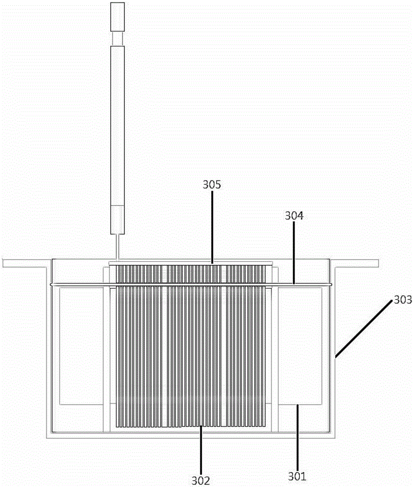
请参见图2,该电抗器包括:磁芯301、线圈302、绝缘纸305、灌封胶以及外壳303;其中:Referring to FIG. 2, the reactor includes: a
线圈302绕制于磁芯301上,具体的缠绕方式可以视其应用环境而定,此处不做限定,均在本申请的保护范围内。The
磁芯301和线圈302通过半灌封技术,被灌封胶灌封于外壳303内;具体的,该磁芯301完全埋入灌封胶中,也即灌封胶完全盖住磁芯301,形成的灌封胶面304略高于磁芯301;线圈302的一部分被埋入灌封胶中,而其高于灌封胶面304的另一部分则裸露在空气中,与空气直接接触,散热效果好。并且,半灌封技术能够减少灌封胶的用量,进而相比全灌封方案减轻了重量并降低了成本。The
绝缘纸305设置于线圈302的裸露部分上,位于线圈302与外部机箱之间,代替全灌封方案中的灌封胶以及现有技术中半灌封方案增加的外壳高度,来实现半灌封技术下线圈302与机箱之间的绝缘,使外壳303的高度仅高于线圈302而低于预设高度即可,也即降低了外壳高度,避免了因外壳高度增加而导致的整体重量、体积及成本的增加。换种方式来说,用绝缘纸305绝缘电抗器裸露的线圈302与外部机箱,使得灌封胶只需盖住磁芯301的半灌封要求能够被满足,进而在满足安全距离的前提下减少灌封胶用量。The
该预设高度的选值可以视其具体应用环境而定,此处不做限定,只要保证线圈302能够低于外壳303的边缘即可,且该选值不宜过大,以确保外壳303的尺寸较小,各种能够实现上述要求的方案均在本申请的保护范围内。The value of the preset height can be determined according to its specific application environment, which is not limited here, as long as the
本实施例提供的该电抗器,通过半灌封技术减少灌封胶的用量,并通过绝缘纸305的上述设置来实现外壳303高度的降低,从而达到减少电抗器的重量、成本及体积的目的。In the reactor provided in this embodiment, the amount of potting glue is reduced by the semi-potting technology, and the height of the
本实用新型另一实施例给出了一种具体的电抗器,在上一实施例和图2的基础之上,优选的,其绝缘纸305完全覆盖线圈302朝向外部机箱的一面,最好覆盖住线圈302之后还能有所剩余,进而能够确保两者之间的绝缘效果;而其具体面积设置可以视其应用环境而定,此处不做限定,均在本申请的保护范围内。Another embodiment of the present invention provides a specific reactor. On the basis of the previous embodiment and FIG. 2, preferably, the
另外,在进行电抗器设计时,为了减少因为绝缘而增加的灌胶量和外壳高度,其外壳303的高度需要低于预设高度;同时,为了确保电抗器的应用要求,其外壳303的高度不仅要高于线圈302,还要进一步满足电抗器的散热要求;也就是说,该电抗器的灌胶量和外壳高度在保证相应绝缘要求的同时,只要保证散热即可。实际应用中,该灌封胶可以采用导热硅胶,此处不做限定,视其应用环境而定,只要满足导热和绝缘要求的材料均在本申请的保护范围内。In addition, when designing the reactor, in order to reduce the increase in the amount of glue and the height of the shell due to insulation, the height of the
再者,优选的,其绝缘纸305的厚度满足电抗器接收电压的耐压要求,不同的系统电压下其绝缘纸305的厚度可以随之变化,使得该电抗器能够在确保安规耐压前提下,降低自身的整体重量。Furthermore, preferably, the thickness of the
其余结构及原理与上述实施例相同,此处不再一一赘述。The rest of the structures and principles are the same as the above-mentioned embodiments, and will not be repeated here.
本实用新型另一实施例还提供了一种电抗器的应用装置,包括如上述任一所述的电抗器。Another embodiment of the present invention also provides a reactor application device, including the reactor described above.
比如逆变器,其中的电抗器即可采用上述实施例所述的电抗器,尤其是组串式逆变器,通过上述电抗器的应用能够顺应组串式逆变器高频化以及小型化的发展趋势。For example, in an inverter, the reactors described in the above embodiments can be used as the reactors, especially the string inverters. The application of the above reactors can conform to the high frequency and miniaturization of the string inverters. development trend.
该电抗器的具体结构及原理可以参见上述实施例,此处不再一一赘述。For the specific structure and principle of the reactor, reference may be made to the above-mentioned embodiments, which will not be repeated here.
本实用新型中各个实施例采用递进的方式描述,每个实施例重点说明的都是与其他实施例的不同之处,各个实施例之间相同相似部分互相参见即可。对于实施例公开的装置而言,由于其与实施例公开的方法相对应,所以描述的比较简单,相关之处参见方法部分说明即可。The various embodiments of the present invention are described in a progressive manner, and each embodiment focuses on the differences from other embodiments, and the same and similar parts between the various embodiments can be referred to each other. As for the device disclosed in the embodiment, since it corresponds to the method disclosed in the embodiment, the description is relatively simple, and the relevant part can be referred to the description of the method.
以上所述,仅是本实用新型的较佳实施例而已,并非对本实用新型作任何形式上的限制。虽然本实用新型已以较佳实施例揭露如上,然而并非用以限定本实用新型。任何熟悉本领域的技术人员,在不脱离本实用新型技术方案范围情况下,都可利用上述揭示的方法和技术内容对本实用新型技术方案做出许多可能的变动和修饰,或修改为等同变化的等效实施例。因此,凡是未脱离本实用新型技术方案的内容,依据本实用新型的技术实质对以上实施例所做的任何简单修改、等同变化及修饰,均仍属于本实用新型技术方案保护的范围内。The above descriptions are only preferred embodiments of the present invention, and do not limit the present invention in any form. Although the present invention has been disclosed above with preferred embodiments, it is not intended to limit the present invention. Any person skilled in the art, without departing from the scope of the technical solution of the present invention, can utilize the methods and technical contents disclosed above to make many possible changes and modifications to the technical solution of the present invention, or be modified to equivalent changes. Equivalent Example. Therefore, without departing from the content of the technical solution of the present invention, any simple modifications, equivalent changes and modifications made to the above embodiments according to the technical essence of the present invention still fall within the protection scope of the technical solution of the present invention.
Claims (9)
Priority Applications (1)
| Application Number | Priority Date | Filing Date | Title |
|---|---|---|---|
| CN201920512563.7U CN209980958U (en) | 2019-04-16 | 2019-04-16 | Reactor and application device thereof |
Applications Claiming Priority (1)
| Application Number | Priority Date | Filing Date | Title |
|---|---|---|---|
| CN201920512563.7U CN209980958U (en) | 2019-04-16 | 2019-04-16 | Reactor and application device thereof |
Publications (1)
| Publication Number | Publication Date |
|---|---|
| CN209980958U true CN209980958U (en) | 2020-01-21 |
Family
ID=69257976
Family Applications (1)
| Application Number | Title | Priority Date | Filing Date |
|---|---|---|---|
| CN201920512563.7U Active CN209980958U (en) | 2019-04-16 | 2019-04-16 | Reactor and application device thereof |
Country Status (1)
| Country | Link |
|---|---|
| CN (1) | CN209980958U (en) |
-
2019
- 2019-04-16 CN CN201920512563.7U patent/CN209980958U/en active Active
Similar Documents
| Publication | Publication Date | Title |
|---|---|---|
| WO2015120802A1 (en) | Inductor coil and electromagnetic component | |
| CN202587443U (en) | Novel electromagnetic heating device | |
| CN209980958U (en) | Reactor and application device thereof | |
| CN203070844U (en) | Brake resistor with aluminum casing | |
| CN214377996U (en) | A medium and high power wireless charging coil structure | |
| CN209072351U (en) | Photovoltaic DC-to-AC converter shell | |
| CN107446513A (en) | The special reinforced Kapton Tape of explosion-proof lightning arrester | |
| CN203596259U (en) | Epoxy poured dry-type transformer longitudinal insulation structure | |
| CN102543391A (en) | Transformer structure | |
| CN207397920U (en) | An inductance for high-power AC charging pile | |
| CN208061843U (en) | A kind of Novel reactor encapsulating device | |
| CN207009270U (en) | It is a kind of can noise reduction high efficiency inductor | |
| CN202549584U (en) | Annular inductance embedment encapsulation fixing structure for photovoltaic inverter | |
| CN107799282A (en) | One kind radiating high frequency transformer, reactor and power electronic equipment | |
| CN112563004A (en) | Medium-high power wireless charging coil structure | |
| CN220933867U (en) | Encapsulation inversion inductance | |
| CN106024385B (en) | A kind of chip high voltage ceramic capacitor | |
| CN219303430U (en) | Transformer device | |
| CN222762741U (en) | An inductor structure with heat dissipation function | |
| CN210926001U (en) | Semiconductor packaging structures and electronic products | |
| CN208027893U (en) | A kind of dry-type transformer | |
| CN203982955U (en) | Reactor device | |
| CN207518502U (en) | A kind of Novel motor controller device integrated structure | |
| CN205140674U (en) | Transformer for distributed generator | |
| CN223450667U (en) | A high-voltage, high-power magnetic device and inverter equipment |
Legal Events
| Date | Code | Title | Description |
|---|---|---|---|
| GR01 | Patent grant | ||
| GR01 | Patent grant |