CN209900185U - Drainage device - Google Patents
Drainage device Download PDFInfo
- Publication number
- CN209900185U CN209900185U CN201721720665.5U CN201721720665U CN209900185U CN 209900185 U CN209900185 U CN 209900185U CN 201721720665 U CN201721720665 U CN 201721720665U CN 209900185 U CN209900185 U CN 209900185U
- Authority
- CN
- China
- Prior art keywords
- drainage
- drainage device
- interface
- buckle
- connecting portion
- Prior art date
- Legal status (The legal status is an assumption and is not a legal conclusion. Google has not performed a legal analysis and makes no representation as to the accuracy of the status listed.)
- Active
Links
Images


Landscapes
- External Artificial Organs (AREA)
Abstract
本实用新型提供一种引流装置,用于肛瘘及肛周脓肿患者术后创面恢复,所述引流装置包括连接部及引流部,所述引流部安装于所述连接部上,所述引流部开设腔体,且一端封闭,所述引流部的另一端设有一接口,所述接口用于连接外部冲洗创面装置,所述引流部一侧设置有若干与所述引流部的腔体贯通的第一孔洞。本实用新型提供的引流装置,结构简单,操作容易,有效减少患者的痛苦。
The utility model provides a drainage device, which is used for postoperative wound recovery of patients with anal fistula and perianal abscess. a cavity, and one end is closed, the other end of the drainage part is provided with an interface, the interface is used to connect an external irrigating wound surface device, and one side of the drainage part is provided with a plurality of first holes that communicate with the cavity of the drainage part holes. The drainage device provided by the utility model has the advantages of simple structure and easy operation, and can effectively reduce the pain of patients.
Description
技术领域technical field
本实用新型涉及肛肠科治疗装置领域,尤其涉及一种引流装置。The utility model relates to the field of anorectal treatment devices, in particular to a drainage device.
背景技术Background technique
根据肛腺感染理论,肛周脓肿是细菌感染肛隐窝形成炎症反应,并经肛腺导管蔓延至肛周各组织间隙发生的急慢性化脓性疾病。若不及时治疗或治疗不当,后期会形成肛瘘,而肛瘘继发感染,又会形成肛周脓肿,因而肛周脓肿、肛瘘不仅是一种疾病的不同发展阶段,而且两者会相互影响,关系密切。目前手术是临床上有效的治疗方法,手术治疗肛周脓肿常采用分次手术疗法,即先切开引流脓液,脓液充分引流,脓腔随之逐渐缩小,脓腔壁结缔组织增生,使脓腔缩窄,形成或直或弯的管道,待肛瘘形成之后再进行二期手术,对于复杂性肛瘘采用隧道式拖线术、置管术可以最大限度地避免了肛门周围组织的损伤,有效地保护了肛门直肠正常的形态和功能的完整,以及最大限度减少瘢痕组织引起的肛管缺损,但操作过程繁琐,置管术的冲洗过程中牵拉橡胶导尿管及更换引流装置时反复穿探脓腔,使患者剧烈痛苦,且橡胶导尿管不易长期留置,长时间留置橡胶变脆、断裂,甚至掉入深部创面继发感染。拖线长时间留置亦会出现变质、恶臭等问题,需定期更换。对于需要长时间留置引流装置的病患如克罗恩肛周病变患者,显然痛苦更大。According to the theory of anal gland infection, perianal abscess is an acute and chronic purulent disease caused by bacterial infection of anal crypts to form an inflammatory reaction and spread to the perianal tissue space through the anal gland duct. If not treated in time or improperly treated, anal fistula will form in the later stage, and secondary infection of anal fistula will lead to the formation of perianal abscess. Therefore, perianal abscess and anal fistula are not only different stages of development of a disease, but also affect each other. close. At present, surgery is a clinically effective treatment method. Surgical treatment of perianal abscess often adopts fractional surgery, that is, the pus is first incised and drained, and the pus is fully drained. The abscess cavity is narrowed and a straight or curved channel is formed. After the anal fistula is formed, the second-stage operation is performed. For the complex anal fistula, the tunnel-type dragging technique and catheter placement can minimize the damage to the tissues around the anus and are effective. It protects the integrity of the normal form and function of the anorectum, and minimizes the anal canal defect caused by scar tissue, but the operation process is cumbersome. Exploring the abscess cavity causes severe pain for the patient, and the rubber catheter is not easy to indwell for a long time, and the rubber becomes brittle, broken, and even falls into the deep wound surface for secondary infection. If the drag wire is left for a long time, problems such as deterioration and odor will occur, and it needs to be replaced regularly. For patients who need to indwell a drainage device for a long time, such as patients with Crohn's perianal disease, it is obviously more painful.
实用新型内容Utility model content
有鉴于此,有必要提供一种引流装置,其更易使用,操作便捷且能减轻患者痛苦。In view of this, it is necessary to provide a drainage device, which is easier to use, convenient to operate and can relieve the pain of patients.
一种引流装置,所述引流装置包括连接部及引流部,所述引流部安装于所述连接部上,所述引流部开设腔体,且一端封闭,所述引流部的另一端设有一接口,所述接口用于连接外部冲洗创面装置,所述引流部一侧设置有若干与所述引流部的腔体贯通的第一孔洞。A drainage device, the drainage device comprises a connection part and a drainage part, the drainage part is installed on the connection part, the drainage part has a cavity, and one end is closed, and the other end of the drainage part is provided with an interface , the interface is used to connect an external irrigating wound surface device, and one side of the drainage portion is provided with a plurality of first holes that communicate with the cavity of the drainage portion.
进一步的,所述引流装置还包括祛腐部,所述祛腐部安装于所述连接部背离所述引流部的一侧,所述祛腐部上设置有另一接口,所述祛腐部的接口与所述外部冲洗创面装置连接。Further, the drainage device further comprises a rot removal part, the rot removal part is installed on the side of the connection part away from the drainage part, another interface is provided on the rot removal part, and the rot removal part is installed on the side of the connection part away from the drainage part. The interface is connected with the external irrigating wound surface device.
进一步的,所述连接部的一端设有第一卡扣,另一端设有第一卡槽,所述第一卡扣和第一卡槽卡合连接。Further, one end of the connecting portion is provided with a first snap, and the other end is provided with a first snap slot, and the first snap is connected with the first snap slot.
进一步的,所述连接部的另一端还设置有若干第二卡槽,所述引流装置弯曲成环状后,所述引流部的接口与对应的所述第二卡槽卡合连接。Further, the other end of the connecting portion is further provided with a plurality of second clamping slots, and after the drainage device is bent into a ring shape, the interface of the drainage portion is snap-connected with the corresponding second clamping slots.
进一步的,所述引流装置弯曲成环状后,所述祛腐部的接口与对应的所述第二卡槽卡合连接。Further, after the drainage device is bent into a ring shape, the interface of the anticorrosion part is connected with the corresponding second card slot in a snap-fit connection.
进一步的,所述祛腐部一侧设置有第二孔洞,所述第二孔洞两侧设置有若干毛刺,所述毛刺用于祛除创面脓腐以及刺激创面加快愈合。Further, a second hole is arranged on one side of the rot removal part, and a plurality of burrs are arranged on both sides of the second hole, and the burr is used to remove pus and rot on the wound surface and stimulate the wound surface to speed up healing.
进一步的,由所述引流部和祛腐部的接口端至另一端,所述第一孔洞和第二孔洞的直径逐渐变大。Further, the diameters of the first hole and the second hole gradually increase from the interface end of the drainage part and the rot removal part to the other end.
进一步的,所述连接部两侧设有第三卡槽,所述引流部和祛腐部分别设有第二卡扣和第三卡扣,所述第二卡扣和第三卡扣分别与所述连接部两侧的所述第三卡槽卡合,使所述引流部和祛腐部连接于所述连接部。Further, the connecting portion is provided with a third slot on both sides, the drainage portion and the rot removal portion are respectively provided with a second buckle and a third buckle, and the second buckle and the third buckle are respectively connected with the The third card grooves on both sides of the connecting portion are engaged, so that the drainage portion and the rot removal portion are connected to the connecting portion.
进一步的,所述引流部和祛腐部横截面形状为月牙状。Further, the cross-sectional shapes of the drainage part and the decay removal part are crescent-shaped.
进一步的,所述引流装置由硅胶制成。Further, the drainage device is made of silica gel.
本实用新型提供的引流装置,结构简单,操作容易,减少对医生经验的依赖,对于复杂性肛瘘、肛周脓肿范围广、脓腔大的患者,避免多次更换引流装置带来的痛苦,后续治疗顺应性好,正常饮食及作息,有利于疾病恢复,减少患者因疼痛所引起的精神紧张、抑郁等精神失常。The drainage device provided by the utility model has the advantages of simple structure, easy operation, less dependence on the doctor's experience, and for patients with complex anal fistulas, a wide range of perianal abscesses and a large abscess cavity, the pain caused by repeated replacement of the drainage device is avoided, and the follow-up Good compliance with the treatment, normal diet and work and rest, are conducive to the recovery of the disease, and reduce the mental disorders such as mental tension and depression caused by pain.
附图说明Description of drawings
图1为本实用新型一实施例中的引流装置的结构示意图。FIG. 1 is a schematic structural diagram of a drainage device in an embodiment of the present invention.
图2为本实用新型一实施例中的引流装置的分离结构示意图。2 is a schematic diagram of a separation structure of a drainage device in an embodiment of the present invention.
图3为本实用新型一实施例中的引流装置从另一视角的分离结构示意图。3 is a schematic diagram of the separation structure of the drainage device in an embodiment of the present invention from another perspective.
主要元件符号说明Description of main component symbols

如下具体实施方式将结合上述附图进一步说明本实用新型。The following specific embodiments will further illustrate the present invention with reference to the above drawings.
具体实施方式Detailed ways
下面将结合本实用新型实施例中的附图,对本实用新型实施例中的技术方案进行清楚、完整地描述,显然,所描述的实施例是仅仅本实用新型的一部分实施例,而不是全部的实施例。基于本实用新型中的实施例,本领域普通技术人员在没有做出创造性劳动前提下所获得的所有其他实施例,都属于本实用新型保护的范围。The technical solutions in the embodiments of the present utility model will be clearly and completely described below with reference to the accompanying drawings in the embodiments of the present utility model. Obviously, the described embodiments are only a part of the embodiments of the present utility model, but not all of them. Example. Based on the embodiments of the present invention, all other embodiments obtained by those of ordinary skill in the art without creative work fall within the protection scope of the present invention.
需要说明的是,当组件被称为“固定于”另一个组件,它可以直接在另一个组件上或者也可以存在居中的组件。当一个组件被认为是“连接”另一个组件,它可以是直接连接到另一个组件或者可能同时存在居中组件。当一个组件被认为是“设置于”另一个组件,它可以是直接设置在另一个组件上或者可能同时存在居中组件。It should be noted that when a component is referred to as being "fixed to" another component, it can be directly on the other component or there may also be a centered component. When a component is considered to be "connected" to another component, it may be directly connected to the other component or there may be a co-existence of an intervening component. When a component is considered to be "set on" another component, it may be directly set on the other component or there may be a co-existing centered component.
除非另有定义,本文所使用的所有的技术和科学术语与属于本实用新型的技术领域的技术人员通常理解的含义相同。本文中在本实用新型的说明书中所使用的术语只是为了描述具体的实施例的目的,不是旨在于限制本实用新型。本文所使用的术语“或/及”包括一个或多个相关的所列项目的任意的和所有的组合。Unless otherwise defined, all technical and scientific terms used herein have the same meaning as commonly understood by one of ordinary skill in the technical field to which the present invention belongs. The terms used in the description of the present invention herein are only for the purpose of describing specific embodiments, and are not intended to limit the present invention. As used herein, the term "or/and" includes any and all combinations of one or more of the associated listed items.
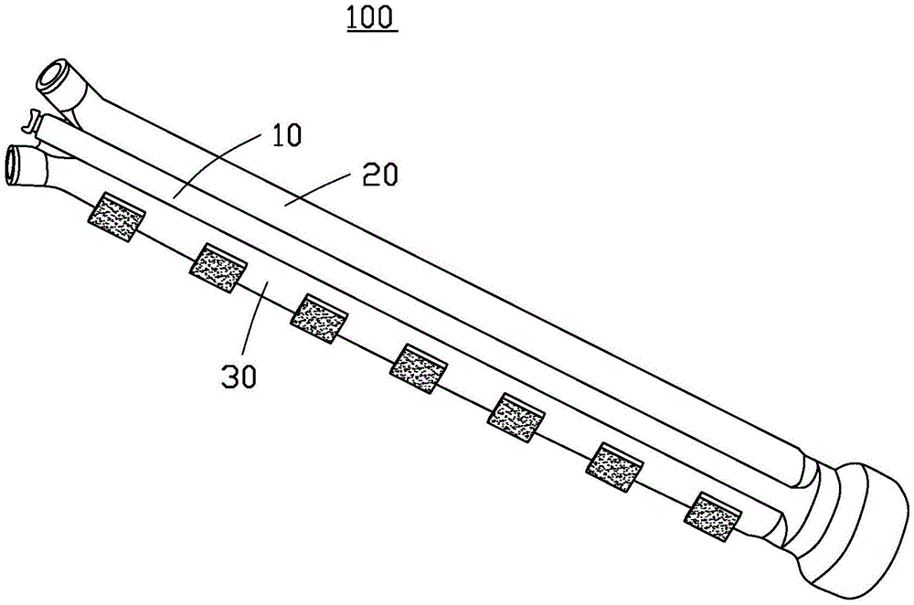
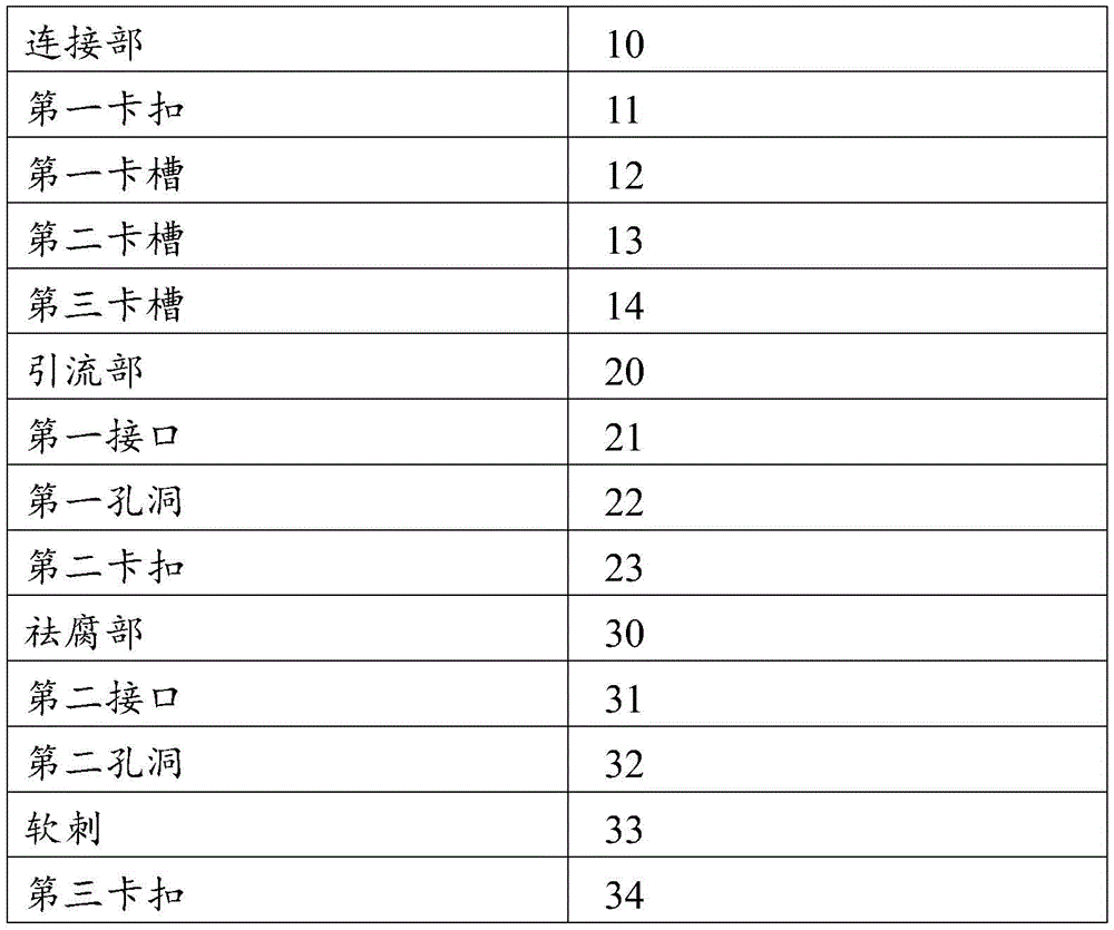
请参阅图1,图1为本实用新型一实施方式中的引流装置100的结构示意图,所述引流装置100主要用于治疗肛瘘、肛周脓肿等肛肠疾病,所述引流装置100包括连接部10、引流部20及祛腐部30,所述引流部20和祛腐部30均与所述连接部10连接。Please refer to FIG. 1 . FIG. 1 is a schematic structural diagram of a
请参阅图2和图3,图2和图3为本实用新型一实施方式中的引流装置100的分离结构示意图,在本实施方式中,所述连接部10的横截面大体为一椭圆体,所述连接部10为实心或者空心,在本实施方式中,所述连接部10为实心,所述连接部10包括两个端部,为方便描述,两个端部分别定义为第一端和第二端。所述连接部10的第一端设置有第一卡扣11,所述连接部10的第二端的形状为圆台状,所述连接部10的第二端设置有与所述第一卡扣11相适配的第一卡槽12,所述第一卡扣11与第一卡槽12卡合后可以实现所述连接部10两端的连接,所述连接部10的第二端还设置有两个第二卡槽13,在本实施方式中,两个所述第二卡槽13位于所述第一卡槽12两侧,所述第二卡槽13用于连接所述引流装置100的所述引流部20和祛腐部30,所述连接部10的相对两侧壁上分别设有第三卡槽14,两个所述第三卡槽14用于分别连接所述引流装置100的所述引流部20和祛腐部30,以使所述引流部20和祛腐部30卡合于所述连接部10两侧。Please refer to FIGS. 2 and 3 . FIGS. 2 and 3 are schematic diagrams of the separation structure of the
所述引流部20为一中空管状体,包括一腔体(未标号)。本实施方式中,所述引流部20的横截面呈月牙状,所述引流部20的一端为封闭结构,另一端设有一第一接口21,所述第一接口21与其中一所述第二卡槽13卡合,所述第一接口21用于连接外部冲洗创面的装置(图未示),所述外部冲洗创面的装置用于向所述第一接口21中注入液体,所述液体可以为药水。所述引流部20的一侧均匀设置有多个与所述腔体贯通的第一孔洞22,所述第一孔洞22用于引导冲洗过创面的液体从所述引流部20流出,多个所述第一孔洞22设置有不同的大小,在本实施方式中,由所述第一接口21一端至所述引流部20另一端的方向,所述第一孔洞22的直径逐渐变大,设置由小变大的所述第一孔洞22主要为了防止冲洗创面的液体引流过快,确保冲洗创面的液体可以流到所述引流部20的另一端,可以冲洗患者整个创面,所述引流部20的另一侧设有多个第二卡扣23,在本实施方式中,所述第二卡扣23为均匀排布,增加连接的紧密性,所述第二卡扣23与所述第三卡槽14相卡合,用于使所述引流部20连接于所述连接部10上。The
所述祛腐部30与所述引流部20结构相似,所述祛腐部30为一中空管状体,包括一腔体(未标号)。本实施方式中,所述祛腐部30的横截面呈月牙状,所述祛腐部30一端为封闭结构,另一端设置有用于连接所述外部冲洗创面装置的第二接口31,所述第二接口31可与另一所述第二卡槽13卡合,所述祛腐部30的一侧均匀设置有多个与所述腔体贯通的第二孔洞32,所述第二孔洞32用于引流冲洗过创面的液体,由所述第二接口31一端至所述祛腐部30另一端的方向,所述第二孔洞32的直径逐渐变大,在所述第二孔洞32的两侧均匀设置有若干软刺33,所述软刺33用于祛除创面的脓腐同时通过异物刺激引起瘘道周围组织与括约肌炎性反应而粘连固定,有利于创面的愈合。所述祛腐部30的另一侧均匀设置有若干第三卡扣34,所述第三卡扣34与另一所述第三卡槽14相卡合,用于使所述祛腐部30连接于所述连接部10上。The
所述引流装置100整体由硅胶制成,可以长期留置在患者体内,所述引流装置100整体通过弯曲成圆环状后,通过所述第一卡扣11与所述第二卡槽12卡合以及所述第一接口21和第二接口31分别和两个所述第二卡槽13卡合,用于固定在患者伤口。The
所述引流装置100主体置于患者创面中,两端留在患者体外,所述软刺33可以祛除创面的脓腐和刺激创面愈合,将所述第一接口21和第二接口31接入冲洗创面装置,冲洗液体通过所述第一接口21和第二接口31进入并通过所述第一孔洞22和第二孔洞32对创面进行冲洗和引流,完成后所述引流装置100的两端卡合,固定在患者伤口上。The main body of the
本实用新型提供的引流装置,将肛瘘、肛周脓肿术后创面愈合各阶段所需要的祛腐、冲洗、引流各作用融入同一装置中,避免了患者更换引流装置的痛苦,且便于长期留置及更换。随着脓腔的缩小,轻轻撕除即可,独特的接口使更换更佳便捷、顺滑,最大限度的减轻患者的痛苦。结构简单,操作便捷,对于技术要求不高,有利于疾病恢复,减少患者因疼痛所引起的精神紧张、抑郁等表现。The drainage device provided by the utility model integrates the functions of removing decay, rinsing and drainage required by various stages of wound healing after anal fistula and perianal abscess into the same device, avoiding the pain of changing the drainage device for patients, and is convenient for long-term indwelling and drainage. replace. As the abscess cavity shrinks, it can be gently torn off. The unique interface makes the replacement more convenient and smooth, which minimizes the pain of the patient. The structure is simple, the operation is convenient, and the technical requirements are not high, which is beneficial to the recovery of the disease and reduces the mental stress and depression caused by the pain of the patient.
本技术领域的普通技术人员应当认识到,以上的实施方式仅是用来说明本实用新型,而并非用作为对本实用新型的限定,只要在本实用新型的实质精神范围的内,对以上实施方式所作的适当改变和变化都落在本实用新型要求保护的范围的内。Those of ordinary skill in the art should realize that the above embodiments are only used to illustrate the present invention, but not to limit the present invention. Appropriate changes and changes made all fall within the scope of the claimed protection of the present invention.
Claims (10)
Priority Applications (1)
| Application Number | Priority Date | Filing Date | Title |
|---|---|---|---|
| CN201721720665.5U CN209900185U (en) | 2017-12-11 | 2017-12-11 | Drainage device |
Applications Claiming Priority (1)
| Application Number | Priority Date | Filing Date | Title |
|---|---|---|---|
| CN201721720665.5U CN209900185U (en) | 2017-12-11 | 2017-12-11 | Drainage device |
Publications (1)
| Publication Number | Publication Date |
|---|---|
| CN209900185U true CN209900185U (en) | 2020-01-07 |
Family
ID=69024846
Family Applications (1)
| Application Number | Title | Priority Date | Filing Date |
|---|---|---|---|
| CN201721720665.5U Active CN209900185U (en) | 2017-12-11 | 2017-12-11 | Drainage device |
Country Status (1)
| Country | Link |
|---|---|
| CN (1) | CN209900185U (en) |
Cited By (1)
| Publication number | Priority date | Publication date | Assignee | Title |
|---|---|---|---|---|
| CN109893686A (en) * | 2017-12-11 | 2019-06-18 | 丁雅卿 | Drainage device |
-
2017
- 2017-12-11 CN CN201721720665.5U patent/CN209900185U/en active Active
Cited By (2)
| Publication number | Priority date | Publication date | Assignee | Title |
|---|---|---|---|---|
| CN109893686A (en) * | 2017-12-11 | 2019-06-18 | 丁雅卿 | Drainage device |
| CN109893686B (en) * | 2017-12-11 | 2023-11-24 | 上海中医药大学附属龙华医院 | Drainage device |
Similar Documents
| Publication | Publication Date | Title |
|---|---|---|
| CN107670160B (en) | Drains that prevent damage to surrounding tissue when pulled out | |
| MX2020002065A (en) | Ureteral and bladder catheters and methods of inducing negative pressure to increase renal perfusion. | |
| CN108671362A (en) | A kind of double balloon conduit external members for expanding ureter | |
| CN106039527B (en) | High-flow anti-blocking flushable drainage catheter for orthopedics department | |
| CN209900185U (en) | Drainage device | |
| CN204582265U (en) | Flushable and the device of drainage tube and the convenient dredging drainage tube blocked can be prevented | |
| CN109893686B (en) | Drainage device | |
| CN118987380B (en) | Lymph drainage device and system | |
| CN203556045U (en) | Double-cavity nose bile drainage tube | |
| CN220877383U (en) | Anti-blocking drainage device | |
| CN221229720U (en) | Abdominal drainage tube | |
| CN205964683U (en) | Washout type drainage tube | |
| CN210020780U (en) | Anal fistula irrigation drainage medicine tube | |
| CN204932539U (en) | Locking alignment Double cavity pig tail conduit | |
| CN108498932B (en) | Anal fistula flushing float wire | |
| CN207024379U (en) | Anal fistula flushing float wire | |
| CN210644711U (en) | An anal fistula irrigation and drainage device | |
| CN221130554U (en) | Stent tube and common bile duct drainage device | |
| CN221384609U (en) | Annular fixed drainage flushing device | |
| CN207401004U (en) | A kind of big side openings conduction pipe of asymmetry applied to abscess of breast | |
| CN221206293U (en) | Hip joint flushing and drainage assembly | |
| CN219166570U (en) | Perianal abscess puncture drainage tube assembly | |
| RU58365U1 (en) | DRAINAGE FOR DRAINING ABCESSES OF THE ABDOMINAL CAVITY AND FOREIGN SPACE | |
| CN215995017U (en) | Improved anal fistula postoperative drainage flushing device | |
| CN223490169U (en) | A flushing and drainage tube for adjuvant treatment of complex high-level anal fistulas after surgery. |
Legal Events
| Date | Code | Title | Description |
|---|---|---|---|
| GR01 | Patent grant | ||
| GR01 | Patent grant |