CN203090100U - Syringe with a needle - Google Patents
Syringe with a needle Download PDFInfo
- Publication number
- CN203090100U CN203090100U CN 201320093015 CN201320093015U CN203090100U CN 203090100 U CN203090100 U CN 203090100U CN 201320093015 CN201320093015 CN 201320093015 CN 201320093015 U CN201320093015 U CN 201320093015U CN 203090100 U CN203090100 U CN 203090100U
- Authority
- CN
- China
- Prior art keywords
- sleeve
- needle
- rod
- syringe
- operating
- Prior art date
- Legal status (The legal status is an assumption and is not a legal conclusion. Google has not performed a legal analysis and makes no representation as to the accuracy of the status listed.)
- Expired - Fee Related
Links
Images


Landscapes
- Infusion, Injection, And Reservoir Apparatuses (AREA)
Abstract
本实用新型关于一种注射器,其包含有一组合式注射器本体、一药剂容器、一注射推杆、一针头与一护盖,该组合式注射器本体主要由容置套筒与操作套筒可拆组地组合而成,使内装有固定剂量注射用药剂的药剂容器可更换地组设其中,组设在操作套筒中的注射推杆能推抵药剂容器中的活塞,针头可拆组地装设于容置套筒上,针头的针体穿刺药剂容器的封闭端盖而伸入其中,护盖可拆组的套设于针头与容置套筒外侧,以此利用内装有固定剂量注射用药剂的药剂容器与针头为可抛弃式的构件,以符合注射药剂的使用安全性,其余构件则能多次重复再利用,使其能节省材料,减少不必要的材料浪费。
The utility model relates to a syringe, which includes a combined syringe body, a medicine container, an injection push rod, a needle and a protective cover. The combined syringe body is mainly composed of an accommodation sleeve and an operating sleeve that can be disassembled. It is assembled so that a medicine container containing a fixed dose of injection medicine can be replaceably assembled therein, the injection push rod assembled in the operating sleeve can push the piston in the medicine container, and the needle is detachably installed. On the accommodating sleeve, the needle body of the needle penetrates the closed end cap of the pharmaceutical container and extends into it. The protective cover is removably set on the outside of the needle and the accommodating sleeve, so as to utilize the fixed dose of injection medication contained inside. The pharmaceutical container and needle are disposable components to ensure the safety of injectable pharmaceuticals. The remaining components can be reused multiple times, saving materials and reducing unnecessary material waste.
Description
技术领域 technical field
本实用新型涉及一种注射器,尤指一种固定剂量式的注射器组成构成实用新型。 The utility model relates to a syringe, in particular to a utility model composed of a fixed-dose syringe. the
背景技术 Background technique
目前如胰岛素的注射、小针美容等,均是利用注射器自装有注射药剂的安瓿中抽取预定剂量的药剂,再经由注射器前端的针头刺入人体内而将药剂注入人体内。 At present, such as insulin injection, small needle beauty, etc., all use a syringe to extract a predetermined dose of medicament from an ampoule containing the injection medicament, and then penetrate the human body through the needle at the front end of the syringe to inject the medicament into the human body. the
现有一般注射器在使用时,因其组成构件均接触药剂,基于注射的使用安全性,注射器在使用后,即需将整支注射器的全部构件全部丢弃,故病患花费于注射器的费用居高不下,造成治疗上一项沉重的负担,且使用后的注射器的废弃物量偏多。此外,因注射器自装有注射药剂的安瓿中抽取预定剂量的药剂,再施打于人体上,在此过程中,使用注射器抽取药剂与注射,不易确保固定剂量的注射给药品质,多次自装有注射药剂的安瓿抽取药剂的方式,会有注射器的药剂受到污染的风险。 When the existing general syringe is in use, because its components are all in contact with the drug, based on the safety of the injection, all the components of the entire syringe need to be discarded after use, so the cost of the syringe is high for patients. Not less, causing a heavy burden on the treatment, and the amount of waste of used syringes is too much. In addition, because the syringe draws a predetermined dose of medicine from the ampoule containing the injection medicine, and then injects it on the human body. During this process, using the syringe to draw medicine and inject it is not easy to ensure the quality of fixed-dose injection administration. The method of drawing the medicine from the ampoule containing the injection medicine has the risk of contamination of the medicine in the syringe. the
实用新型内容 Utility model content
本实用新型的主要目的是提供一种注射器,希以此实用新型改善现有注射器使用后全部构件均抛弃的浪费材料问题。 The main purpose of the utility model is to provide a syringe, hoping that the utility model can improve the waste material problem that all components of the existing syringe are discarded after use. the
为达成所述目的,本实用新型所提出的注射器包含有: For achieving said purpose, the syringe proposed by the utility model includes:
一组合式注射器本体,其包含有一容置套筒与一操作套筒,所述容置套筒与操作套筒为轴向贯通的中空体,所述容置套筒包含有一针头连接端部以及一接合端部且分别位于容置套筒轴向的两端,所述操作套筒包含有一组接端部,所述组接端部可拆组的组接于容置套筒的接合端部; A combined syringe body, which includes an accommodating sleeve and an operating sleeve, the accommodating sleeve and the operating sleeve are hollow bodies that pass through the axial direction, and the accommodating sleeve includes a needle connection end and One joint end is located at the two axial ends of the accommodating sleeve respectively. The operation sleeve includes a set of joint ends which can be detachably assembled to the joint end of the accommodating sleeve. ;
一药剂容器,其可更换地装设于组合式注射器本体内,所述药剂容器包含有一中空的容器本体、一封闭端盖以及一活塞,该封闭端盖固接于该容器本体一端所形成的开口处,该活塞气密而能轴向移动地组设于容器本体另一端所形 成的开口内部,药剂容器以其容器本体具有封闭端盖的一端位于所述容置套筒的针头连接端部内; A medicament container, which is replaceably installed in the combined syringe body, the medicament container includes a hollow container body, a closed end cap and a piston, and the closed end cap is fixedly connected to a hole formed by one end of the container body. At the opening, the piston is airtightly and axially movable assembled inside the opening formed at the other end of the container body, and the end of the container body with the closed end cap of the medicament container is located at the needle connection end of the accommodating sleeve. Ministry;
一注射推杆,其包含有一杆体以及设于杆体一端的操作件,所述杆体可轴向移动的装设于组合式注射器本体内且能连接药剂容器的活塞,操作件位于组合式注射器的操作套筒外侧连接杆体; An injection push rod, which includes a rod body and an operating part arranged at one end of the rod body. The rod body is axially movable and installed in the combined syringe body and can be connected to the piston of the medicament container. The operating part is located at the operating part of the combined syringe. Connecting rod outside the sleeve;
一针头,其包含有一套接部以及一内有针孔的针体,所述针体贯穿固定于套接部中,针头以其套接部套接固定于组合式注射器本体的针头连接端,使针体穿过封闭端盖而伸入药剂容器内部;以及 A needle, which includes a socket part and a needle body with a needle hole inside, the needle body is fixed through the socket part, and the needle head is socketed and fixed on the needle connection end of the combined syringe body with its socket part, allowing the needle body to extend into the interior of the medicament container through the closed end cap; and
一护盖,其可拆组地套接于针头与组合式注射器本体的容置套筒外侧。 A protective cover is detachably sleeved on the outside of the housing sleeve of the needle and the combined syringe body. the
优选地,所述容置套筒的接合端部形成有一环形凸缘以及多个位于环形凸缘侧端呈间隔排列的卡钩;所述操作套筒在其组接端部另一端具有一延伸管部,且操作套筒内部在组接端部与延伸管部之间形成有一具有中孔的隔板部,使操作套筒内部空间区隔成一位于组接端部内的装配空间以及一位于延伸管部内的活动空间,所述组接端部外周面形成向外凸伸的翼片部,所述操作套筒的装配空间在组接端部外端部处形成有一装配口,该组接端部在活动空间中邻近装配口处形成有一卡制凸缘,组接端部在邻近延伸管部处的外周壁形成有多个按压弹片以及位于按压弹片周边且连通活动空间的缺槽,按压弹片邻近卡制凸缘的一端为自由端,按压弹片另一端连接延伸管部。 Preferably, the joint end of the accommodating sleeve is formed with an annular flange and a plurality of hooks arranged at intervals at the side end of the annular flange; The inner space of the operating sleeve is divided into an assembly space located in the assembled end and an assembly space located in the extension tube. In the movable space in the pipe part, the outer peripheral surface of the assembly end forms an outwardly protruding fin part, and the assembly space of the operation sleeve forms an assembly port at the outer end of the assembly end, and the assembly end A clamping flange is formed in the movable space adjacent to the assembly port, and a plurality of pressing elastic pieces and slots located on the periphery of the pressing elastic pieces and connected to the movable space are formed on the outer peripheral wall of the assembly end adjacent to the extension pipe portion. One end adjacent to the clamping flange is a free end, and the other end of the pressing spring is connected to the extension pipe. the
优选地,所述容置套筒的接合端部在环形凸缘侧端形成有多个对位凸部,该多个对位凸部与该多个卡钩呈交错排列;所述操作套筒的组接端部在其装配口处进一步形成有多个相应于对位凸部的对位凹部,通过对位凸部与对位凹部的凹凸配合,使容置套筒的接合端部与操作套筒的组接端部组接一起。 Preferably, the joint end of the accommodating sleeve is formed with a plurality of alignment protrusions at the side end of the annular flange, and the plurality of alignment protrusions and the plurality of hooks are arranged in a staggered manner; the operation sleeve The assembly end of the assembly port is further formed with a plurality of alignment concave parts corresponding to the alignment convex parts. Through the concave-convex cooperation of the alignment convex parts and the alignment concave parts, the joint end of the accommodating sleeve and the operation The ganged ends of the sleeves are ganged together. the
优选地,所述操作套筒中,所述隔板部在其中孔周缘形成有一轴向延伸至活动空间内的轴管部,以所述轴管部提供注射推杆穿设其中。 Preferably, in the operation sleeve, the baffle part forms a shaft tube part axially extending into the movable space at the periphery of the hole in the partition part, and the shaft tube part provides an injection push rod passing through it. the
优选地,所述封闭端盖包含有一橡胶材质的封闭盖体以及一外盖体,所述封闭盖体装设于容器本体一端的开口处,外盖体包覆封闭盖体外侧而将封闭盖体封设于容器本体一端的开口,所述外盖体中形成有一孔,使封闭盖体对应容器本体一端开口的中间区段显露于外。 Preferably, the closed end cap includes a rubber closed cover and an outer cover, the closed cover is installed at the opening at one end of the container body, and the outer cover covers the outer side of the closed cover to seal the closed cover The body seals the opening at one end of the container body, and a hole is formed in the outer cover body, so that the middle section of the closing cover corresponding to the opening at one end of the container body is exposed outside. the
优选地,所述注射推杆的杆体包含有一杆端部与一杆连接部且分别位于杆体的轴向两端;所述注射推杆也包含有一滑套,滑套包含有一套体以及一成形 于套体一端的固接部,所述套体可活动地伸入操作套筒的延伸管部的活动空间中且位于轴管部外侧,固接部组接该杆体的杆连接部以及该操作件,所述套体外周面形成有多个导槽,所述导槽各包含有一轴向延伸的直槽部以及一倾斜延伸的斜槽部,该多个导槽分布设置于套体远离固接部的端面的外周面,每一导槽的斜槽部邻近固接部的一端连接其直槽部邻近固接部的一端,斜槽部远离固接部的一端连接侧邻导槽的直槽部远离固接部的一端,使每两相邻的导槽相互串连;所述操作套筒在其延伸管部的活动空间周壁形成有多个导引凸部,每一导引凸部分别置入对应的导槽内的对等位置。 Preferably, the rod body of the injection push rod includes a rod end and a rod connecting portion respectively located at the two axial ends of the rod body; the injection push rod also includes a sliding sleeve, which includes a sleeve body and a forming The fixing part at one end of the sleeve body, the sleeve body can movably extend into the activity space of the extension tube part of the operating sleeve and is located outside the shaft tube part, the fixing part is assembled with the rod connecting part of the rod body and the operating sleeve. A plurality of guide grooves are formed on the outer peripheral surface of the sleeve, and each of the guide grooves includes an axially extending straight groove portion and an obliquely extending inclined groove portion. The outer peripheral surface of the end surface of the connecting part, one end of the inclined groove part of each guide groove adjacent to the fixed part is connected to one end of the straight groove part adjacent to the fixed part, and the end of the inclined groove part far away from the fixed part is connected to the straight side of the adjacent guide groove. The groove part is far away from one end of the fixed part, so that every two adjacent guide grooves are connected in series; the operation sleeve is formed with a plurality of guiding protrusions on the surrounding wall of the movable space of the extension pipe part, and each guiding protrusion Put them into the corresponding position in the corresponding guide groove respectively. the
优选地,所述注射推杆中,该滑套内部形成有一具有内孔的环形挡板以及一自内孔孔缘朝固接部末端方向延伸的接管部,接管部与固接部的内壁之间形成组接空间,接管部的周壁分布设置多个自其末端轴向延伸的切缝,该滑套的固接部上邻近环形挡板处形成有多个连通组接空间的卡接孔,该杆体的杆连接部上形成有一径向凸伸的环凸缘,杆连接部末端形成凸缘,杆体伸入滑套内部,杆体的杆连接部对应插设于滑套内的接管部中,环凸缘抵接于环形挡板侧端,凸缘抵接于接管部末端,所述操作件包含有一旋钮部以及一形成于旋钮部内部呈轴向凸伸的套合管部,套合管部末端形成有多个固定钩,操作件以其旋钮部套设于滑套的固接部外侧,且套合管部伸入固接部内的组接空间且套接于接管部外侧,且该多个固定钩分别卡扣于滑套的固接部的卡接孔中,使操作件、滑套与杆体固接一起。 Preferably, in the injection push rod, an annular baffle with an inner hole and a connecting pipe extending from the edge of the inner hole toward the end of the fixed part are formed inside the sliding sleeve, and the connection between the connecting part and the inner wall of the fixed part A joint space is formed between them, and the peripheral wall of the connecting pipe part is distributed with a plurality of slits extending axially from its end. On the fixed part of the sliding sleeve, a plurality of snap-fit holes connecting the joint space are formed adjacent to the annular baffle plate. A radially protruding ring flange is formed on the rod connecting portion of the rod body, and a flange is formed at the end of the rod connecting portion, the rod body extends into the sliding sleeve, and the rod connecting portion of the rod body is correspondingly inserted into the connecting pipe portion in the sliding sleeve, The ring flange abuts against the side end of the annular baffle, and the flange abuts against the end of the connecting pipe part. The operating part includes a knob part and an axially protruding fitting pipe part formed inside the knob part. The fitting pipe There are a plurality of fixed hooks formed at the end of the part, the operating part is sleeved on the outside of the fixed part of the sliding sleeve with its knob part, and the sleeve tube part extends into the assembly space in the fixed part and is sleeved on the outside of the connecting part, and the A plurality of fixing hooks are respectively buckled in the fastening holes of the fastening part of the sliding sleeve, so that the operating part, the sliding sleeve and the rod body are fixedly connected together. the
优选地,所述操作件的旋钮部外周面形成凹凸状的止滑部。 Preferably, the outer peripheral surface of the knob part of the operating member forms a concave-convex anti-slip part. the
以此注射器的组成构造,其至少包含有以下优点: With the composition structure of this syringe, it at least includes the following advantages:
1.安全性高:本实用新型注射器令其药剂容器封装固定剂量的注射药剂,使其容器本体内的药剂与人体生菌完全隔离,而能直接地排除污染的风险,且本实用新型可令药剂容器及其内部封装的注射用药剂为规格化的制品,使其使用时可以确保固定剂量的注射给药品质,达到良好的使用安全性。 1. High safety: the syringe of the utility model enables its medicament container to encapsulate a fixed dose of injection medicament, so that the medicament in the container body is completely isolated from the human body bacteria, and the risk of contamination can be directly eliminated, and the utility model can make The medicament container and the medicament for injection encapsulated in it are standardized products, which can ensure the quality of fixed-dose injection and achieve good safety in use. the
2.使用方便佳:本实用新型注射器中,其组合式注射器本体的容置套筒与操作套筒为易拆组的组合构造,使其可易于组装药剂容器与更换药剂容器。再者,本实用新型注射器可如充填子弹般的药剂装填机构,在使用时,可省下一般注射器必须从装有注射药剂的安瓿中抽出药剂的时间,故本实用新型可为病患注射药剂时,提供一项使用方便又省力的好帮手。 2. Easy to use: In the syringe of the present utility model, the accommodating sleeve and the operating sleeve of the combined syringe body are a combined structure that can be easily disassembled, making it easy to assemble and replace the drug container. Furthermore, the syringe of the present utility model can be filled with a bullet-like medicament filling mechanism. When in use, it can save the time that a general syringe must extract the medicament from the ampoule containing the injection medicament, so the utility model can be used for injecting medicament to patients. , providing a good helper that is easy to use and labor-saving. the
3.符合环保:本实用新型注射器中,其针头与药剂容器为可更换的抛弃式构件,用以确保注射药剂的使用安全性外,其余的组合式注射器本体、注射推杆以及护盖等构件则可重复多次使用,相较于现有使用一次即整组丢弃的注射器产品,本实用新型注射器的使用能够减少材料不必要的浪费,使用者仅须购买内装固定剂量注射用药剂的药剂容器与针头,即能与组合式注射器本体与注射推杆组合再使用,故能节省材料而降低使用成本。 3. Compliant with environmental protection: In the syringe of the utility model, the needle and the drug container are replaceable disposable components to ensure the safety of the injected drug, and the remaining components such as the combined syringe body, injection push rod and protective cover are It can be used repeatedly. Compared with the existing syringe products that are used once and discarded as a whole, the use of the syringe of the present invention can reduce unnecessary waste of materials, and the user only needs to buy a medicine container with a fixed dose of injection medicine inside. It can be combined with the needle, that is, it can be combined with the combined syringe body and the injection push rod, so it can save materials and reduce the cost of use. the
本实用新型的次要目的,是令该注射器的注射推杆在其杆体与操作件之间进一步附加有一滑套,利用滑套外周面形成包含有直槽部与斜槽部的导槽,搭配组合式注射器本体的操作套筒内壁的导引凸部伸入导槽内,使注射推杆可以轴向直进方式推动组合式注射器本体内的药剂容器的活塞进行注射,其中利用直槽部的长度控制注射量,排除施药由人为因素控制的注射给药模式的不精准问题;另使注射推杆可以螺旋方式朝反方向移动,而注射推杆自组合式注射器本体中朝后拉出,具有较省力的操作方便性。 The secondary purpose of this utility model is to make the injection push rod of the syringe further add a sliding sleeve between the rod body and the operating part, and use the outer peripheral surface of the sliding sleeve to form a guide groove including a straight groove part and a chute part. The guide convex part of the inner wall of the operation sleeve of the combined syringe body extends into the guide groove, so that the injection push rod can push the piston of the medicine container in the combined syringe body in an axial straight way to inject, and the straight groove part is used to inject The length controls the injection volume, eliminating the inaccuracy of the injection mode of drug administration controlled by human factors; in addition, the injection push rod can move in the opposite direction in a spiral manner, and the injection push rod is pulled out from the combined syringe body backward, It has less labor-saving operation convenience. the
本实用新型的另一次要目的,是令组合式注射器本体的容置套筒与操作套筒为卡接组合的构件,并具有按压弹片提供使用者以简便的按压方式解除容置套筒与操作套筒间的卡接状态,使组合式注射器本体易于拆装药剂容器。 Another secondary purpose of this utility model is to make the accommodation sleeve and the operation sleeve of the combined syringe body a snap-fit component, and have a pressing spring to provide the user with a simple pressing method to release the accommodation sleeve and the operation sleeve. The locking state between the sleeves makes the combined syringe body easy to disassemble and assemble the medicament container. the
附图说明 Description of drawings
图1是本实用新型注射器的一优选实施例的立体分解示意图。 Fig. 1 is a three-dimensional exploded schematic view of a preferred embodiment of the syringe of the present invention. the
图2是图1所示注射器优选实施例的细部分解示意图。 Figure 2 is a detailed exploded schematic view of the preferred embodiment of the syringe shown in Figure 1 . the
图3是图1所示注射器优选实施例组合的立体外观示意图。 Fig. 3 is a schematic perspective view of the combination of the preferred embodiment of the syringe shown in Fig. 1 . the
图4是图1所示注射器优选实施例的剖面示意图。 Fig. 4 is a schematic cross-sectional view of a preferred embodiment of the syringe shown in Fig. 1 . the
图5是图1所示注射器优选实施例的另一剖面示意图。 Fig. 5 is another schematic cross-sectional view of the preferred embodiment of the syringe shown in Fig. 1 . the
图6是图1所示注射器优选实施例在注射时的使用状态参考图。 Fig. 6 is a reference view of the preferred embodiment of the syringe shown in Fig. 1 in use during injection. the
图7是图1所示注射器优选实施例,在注射后,进行拆解的操作示意图。 Fig. 7 is a schematic diagram of disassembly operation of the preferred embodiment of the syringe shown in Fig. 1 after injection. the
附图标号说明: Explanation of reference numbers:
1组合式注射器本体 1 combined syringe body
11容置套筒 111针头连接端部
11
112接合端部 113环形凸缘
112
114卡钩 115对位凸部
114
12操作套筒 120组接端部
12
1201装配口 1202卡制凸缘
1201
121延伸管部 122对位凹部
121
123翼片部 124缺槽
123
125按压弹片 126隔板部
127装配空间 128活动空间
127
1281导引凸部 129轴管部
1281 guide
2药剂容器 2 drug containers
20容器本体 21活塞
20
22封闭端盖 220封闭盖体
22
221外盖体 221 outer cover body
3注射推杆 3 injection push rod
30杆体 301杆端部
30
302杆连接部 304环凸缘
302
305凸缘 305 flange
31杆体端块 31 rod body end block
32滑套 321套体
32 sliding
322固接部 323导槽
322
3231直槽部 3232斜槽部
3231
324环形挡板 325接管部
324
3251切缝 326卡接孔
3251
33操作件 331旋钮部
33
332套合管部 333固定钩
332
4针头 4 needles
40套接部 41针体
40
5护盖 50盖体
5
51夹持部 51 clamping part
具体实施方式 Detailed ways
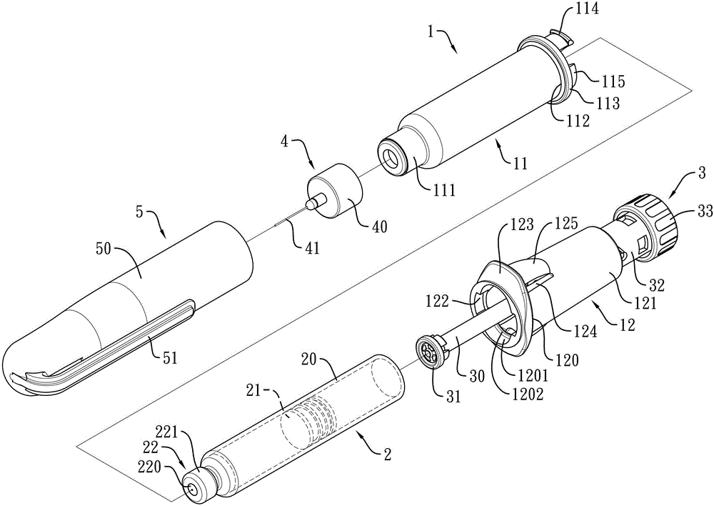
以下配合附图及本实用新型的优选实施例,进一步阐述本实用新型为达成 预定实用新型目的所采取的技术手段。 Below in conjunction with accompanying drawing and preferred embodiment of the present utility model, further set forth the technical means that the present utility model takes for reaching predetermined utility model purpose. the
如图1所示,其揭示本实用新型注射器的一优选实施例,所述注射器包含有一组合式注射器本体1、一药剂容器2、一注射推杆3、一针头4以及一护盖5,其中:
As shown in Figure 1, it discloses a preferred embodiment of the syringe of the present invention, which includes a combined syringe body 1, a
如图1、图2所示,所述组合式注射器本体1包含有一容置套筒11以及一操作套筒12,所述容置套筒11是一内部呈轴向贯通的中空体,所述容置套筒11包含有一针头连接端部111以及一接合端部112,所述针头连接端部111与接合端部112分别位于容置套筒11轴向的两端,所述操作套筒12是一内部呈轴向贯通的中空体,所述操作套筒12包含有一组接端部120,并以所述组接端部120可拆组的组接于容置套筒11的接合端部112,通过容置套筒11与操作套筒12的组合,提供药剂容器2置入定位其中。
As shown in Figures 1 and 2, the combined syringe body 1 includes an
如图1、图2与图4所示,在本优选实施例中,所述容置套筒11的接合端部112形成有一环形凸缘113以及多个位于环形凸缘113侧端呈间隔排列的卡钩114;所述操作套筒12在其组接端部120另一端具有一延伸管部121,且操作套筒12内部在组接端部120与延伸管部121之间形成有一具有中孔的隔板部126,使操作套筒12内部空间区隔成一位于组接端部120内的装配空间127以及一位于延伸管部121内的活动空间128,所述组接端部120外周面形成有向外凸伸的翼片部123,所述操作套筒12的装配空间127在组接端部120外端部处形成有一装配1201,该组接端部120在活动空间128中邻近装配1201处形成有一卡制凸缘1202,组接端部120在邻近延伸管部121处的外周壁形成有多个按压弹片125以及位于按压弹片125周边且连通活动空间128的缺槽124,按压弹片125邻近卡制凸缘1202的一端为自由端,按压弹片125另一端连接延伸管部121,使按压弹片125具有可径向活动及回复的弹性,使容置套筒11的接合端部112组接于操作套筒12的组接端部120,卡钩114伸入装配1201内而卡钩于卡制凸缘1202处,并能利用按压弹片125推抵卡钩114脱离卡制凸缘1202,而使容置套筒11的接合端部112可与操作套筒12的组接端部120拆解。
As shown in Figure 1, Figure 2 and Figure 4, in this preferred embodiment, the
如图4及图5所示,前述操作套筒12中,所述隔板部126也可在其中孔周缘形成一轴向延伸至活动空间128内的轴管部129,以所述轴管部129提供注射推杆3穿设其中。
As shown in Figures 4 and 5, in the
如图1及图2所示,所述药剂容器2可容置注射用药剂,为一抛弃式的构 件,所述药剂容器2可更换地装设于组合式注射器本体1内,在本优选实施例中,所述药剂容器2包含有一容器本体20、一封闭端盖22以及一活塞21,所述容器本体20是一中空体,用以容置注射用药剂,该容器本体20包含有一第一端与一第二端,所述第一端与第二端分别位于容器本体20轴向的两端,容器本体20内的空间在第一端与第二端中各形成开口,所述封闭端盖22封设于容器本体20第一端的开口处,活塞21是气密而能轴向移动地组设于容器本体20的第二端。
As shown in Figures 1 and 2, the
如图1、图2以及图4所示,在本优选实施例中,所述封闭端盖22包含有一封闭盖体220以及一外盖体221,所述封闭盖体220是橡胶之类的材料所制成的构件,并装设于容器本体20的第一端开口处,外盖体221包覆封闭盖体220外侧而将封闭盖体220封设于容器本体20的第一端的开口,所述外盖体221中形成有一孔,使封闭盖体220对应容器本体20第一端开口的中间区段显露于外,用以提供针头4插接连通容器本体20内部的部位,所述药剂容器2可拆组的安装于组合式注射器本体1的容置套筒11与操作套筒12的装配空间中定位,使容器本体20封合有封闭端盖22的第一端伸入容置套筒11的针头连接端部111内,容器本体20的第二端为操作套筒12内的隔板部126所抵止,使药剂容器2被固定于组合式注射器本体1内部。
As shown in Figures 1, 2 and 4, in this preferred embodiment, the
如图1与图2所示,所述注射推杆3可轴向移动地装设于该组合式注射器本体1内,并能连接药剂容器2的活塞21,在本优选实施例中,所述注射推杆3包含有一杆体30以及一操作件33,所述杆体30包含有一杆端部301与一杆连接部302,所述杆端部301与杆连接部302分别位于杆体30轴向的两端,所述杆体30可穿设于组合式注射器本体1内,并能以杆端部301直接抵接药剂容器2的活塞21,或者,杆端部301结合有一圆形的杆体端块31,以该杆体端块31抵接药剂容器2的活塞21,杆体30的杆连接部302伸出组合式注射器本体1的操作套筒12外,所述操作件33位于操作套筒12外侧,组接杆体30的杆连接部302。
As shown in Figures 1 and 2, the
如图1、图2以及图4所示,所述针头4为一抛弃式的构件,所述针头4包含有一套接部40以及一内有针孔的针体41,所述针体41穿设固定于套接部40中,针体41伸出套接部40外的区段为注射段,在套接部40内的区段为穿刺段,所述针头4以其套接部40套接固定于药剂容器2伸出组合式注射器本体1 外侧的具有封闭端盖22的第一端外侧,且使针体41的穿刺段穿刺过封闭端盖22的封闭盖体220而伸入药剂容器2内部。
As shown in Fig. 1, Fig. 2 and Fig. 4, the
如图1至图3与图5所示,所述护盖5具有一个一端为开口端、另一端为封闭的中空盖体,并能套接于针头4以及组合式注射器本体1的容置套筒11外侧,避免使用者或他人为针头4所刺伤,在本优选实施例中,所述护盖5也可在盖体50侧边形成一条状的夹持部51,使护盖5可利用夹持部51夹持于物件上。
As shown in FIGS. 1 to 3 and 5 , the
如图2、图4及图5所示,在本优选实施例中,所述注射推杆3也包含有一滑套32,滑套32包含有一套体321以及一成形于套体321一端的固接部322,所述套体321可活动地伸入操作套筒12的延伸管部121的活动空间128中且位于轴管部129外侧,固接部322则组接该杆体30的杆连接部302以及该操作件33,所述套体321外周面形成有多个导槽323,所述导槽323各包含有一轴向延伸的直槽部3231以及一倾斜延伸的斜槽部3232,该多个导槽323分布设置于套体321远离固接部322的端面的外周面,每一导槽323的斜槽部3232邻近固接部322的一端连接其直槽部3231邻近固接部322的一端,斜槽部3232远离固接部322的一端连接侧邻导槽323的直槽部3231远离固接部322的一端,使每两相邻的导槽323相互串连;所述操作套筒12在其延伸管部121的活动空间128周壁形成有多个导引凸部1281,每一导引凸部1281分别置入对应的导槽323内的对等位置,以此,当导引凸部1281位于滑套32的导槽323的直槽部3231时,使注射推杆3可以轴向推动装设于组合式注射器本体1内的药剂容器2的活塞21,并利用直槽部3231的长度控制注射量;当导引凸部1281位于导槽323的斜槽部3232时,使注射推杆3可以螺旋方式朝反方向移动,而具有较省力的操作方便性。
As shown in Figure 2, Figure 4 and Figure 5, in this preferred embodiment, the
如图2、图4及图5所示,在本优选实施例中,所述注射推杆3的滑套32内部形成有一具有内孔的环形挡板324以及一自内孔孔缘朝固接部322末端方向延伸的接管部325,接管部325与固接部322的内壁之间形成组接空间,接管部325的周壁分布设置有多个自其末端轴向延伸的切缝3251,使接管部325具有扩张与回复的弹性,该滑套32的固接部322上邻近环形挡板324处形成有多个卡接孔326,所述卡接孔326连通组接空间,该杆体30的杆连接部302上形成有一径向凸伸的环凸缘304,杆连接部302的末端形成凸缘305,杆体30伸 入滑套32内部,杆体30的杆连接部302对应插设于滑套32内的接管部325中,环凸缘304抵接于环形挡板324侧端,凸缘305抵接于接管部325末端而组合,所述操作件33包含有一旋钮部331以及一形成于旋钮部331内部呈轴向凸伸的套合管部332,套合管部332末端形成有多个固定钩333,操作件33以其旋钮部331套设于滑套32的固接部322外侧,且套合管部332伸入固接部322内的组接空间且套接于接管部325外侧,且该多个固定钩333分别卡扣于滑套32的固接部322的卡接孔326中,使操作件33、滑套32以及杆体30三者固接一起,操作件33的旋钮部331外周面也可形成凹凸状的止滑部。
As shown in Fig. 2, Fig. 4 and Fig. 5, in this preferred embodiment, an
如图1及图2所示的优选实施例中,所述组合式注射器本体1中,所述容置套筒11的接合端部112也可进一步在环形凸缘113侧端形成多个对位凸部115,该多个对位凸部115与该多个卡钩114呈交错排列;所述操作套筒12的组接端部120也可在其装配口1201处进一步形成多个相应于对位凸部115的对位凹部122,通过对位凸部115与对位凹部122的凹凸配合,而使容置套筒11的接合端部112与操作套筒12的组接端部120稳固地组接一起。
In the preferred embodiment shown in Figures 1 and 2, in the combined syringe body 1, the
如图6所示,本实用新型注射器的优选实施例在使用时,将内装有固定剂量注射用药剂的药剂容器2安装于容置套筒11与操作套筒12组成的组合式注射器本体1内部,并使组设于操作套筒12内的注射推杆3的杆体30上的杆体端块31抵接药剂容器2中的活塞21,再将针头4套接于组合式注射器本体1的针头连接端部111,使针头4的针体41的穿刺段穿刺过封闭端盖22的封闭盖体220而伸入药剂容器2内部,如此,使该注射器呈笔形,提供使用者注射之用。
As shown in Figure 6, when the preferred embodiment of the syringe of the present invention is in use, the
如图7所示,当欲更换药剂容器2时,使用者先将使用过的针头4自组合式注射器本体1的针头连接端部111拆下,再将组合式注射器本体1的容置套筒11与操作套筒12拆解而取出使用过的药剂容器2,其中,在拆解容置套筒11与操作套筒12时,先按压操作套筒12上的按压弹片125,使按压弹片125推抵卡钩114脱离卡制凸缘1202,再自操作套筒12侧端轴向拉动内装有药剂容器2的容置套筒11,使容置套筒11与操作套筒12分离,即可接续将使用过的药剂容器2自容置套筒11中取出,更换内装固定剂量注射用药剂的药剂容器2,重新组装。
As shown in Figure 7, when wanting to replace the
由以上说明可知,本实用新型所提出的注射器中,仅令涉及使用安全性的针头4与内装固定剂量注射用药剂的药剂容器2为抛弃式的构件,其余的组合 式注射器本体1、注射推杆3以及护盖5等均能重复多次再利用,使其可以改善现有注射器使用后全部构件抛弃的材料浪费问题。
As can be seen from the above description, in the syringe proposed by the utility model, only the
以上所述仅是本实用新型的优选实施例而已,并非对本实用新型做任何形式上的限制,虽然本实用新型已以优选实施例披露如上,然而并非用以限定本实用新型,任何本领域的技术人员,在不脱离本实用新型技术方案的范围内,应当可以利用上述揭示的技术内容作出些许改变或修饰为等同变化的等效实施例,但凡是未脱离本实用新型技术方案的内容,依据本实用新型的技术实质对以上实施例所作的任何简单修改、等同变化与修饰,均仍属于本实用新型技术方案的范围内。 The above descriptions are only preferred embodiments of the present utility model, and do not limit the utility model in any form. Although the utility model has been disclosed as above with preferred embodiments, it is not intended to limit the utility model. Anyone in the field Skilled persons, within the scope of the technical solution of the utility model, should be able to use the technical content disclosed above to make some changes or modify equivalent embodiments with equivalent changes. The technical essence of the utility model makes any simple modifications, equivalent changes and modifications to the above embodiments, all still belong to the scope of the technical solution of the utility model. the
Claims (10)
Applications Claiming Priority (2)
| Application Number | Priority Date | Filing Date | Title |
|---|---|---|---|
| TW101214582U TWM444852U (en) | 2012-07-27 | 2012-07-27 | Injector device |
| TW101214582 | 2012-07-27 |
Publications (1)
| Publication Number | Publication Date |
|---|---|
| CN203090100U true CN203090100U (en) | 2013-07-31 |
Family
ID=48090555
Family Applications (1)
| Application Number | Title | Priority Date | Filing Date |
|---|---|---|---|
| CN 201320093015 Expired - Fee Related CN203090100U (en) | 2012-07-27 | 2013-02-28 | Syringe with a needle |
Country Status (2)
| Country | Link |
|---|---|
| CN (1) | CN203090100U (en) |
| TW (1) | TWM444852U (en) |
Cited By (4)
| Publication number | Priority date | Publication date | Assignee | Title |
|---|---|---|---|---|
| CN105288790A (en) * | 2014-06-26 | 2016-02-03 | 群康生技股份有限公司 | syringe |
| CN105311714A (en) * | 2014-06-26 | 2016-02-10 | 群康生技股份有限公司 | Spiral guide mechanism of injector |
| CN108325031A (en) * | 2018-03-08 | 2018-07-27 | 珠海凯生医用科技有限公司 | A kind of electronics pen-type injector |
| CN109106591A (en) * | 2018-09-13 | 2019-01-01 | 北京康祝医疗器械有限公司 | A kind of lancet |
-
2012
- 2012-07-27 TW TW101214582U patent/TWM444852U/en not_active IP Right Cessation
-
2013
- 2013-02-28 CN CN 201320093015 patent/CN203090100U/en not_active Expired - Fee Related
Cited By (7)
| Publication number | Priority date | Publication date | Assignee | Title |
|---|---|---|---|---|
| CN105288790A (en) * | 2014-06-26 | 2016-02-03 | 群康生技股份有限公司 | syringe |
| CN105311714A (en) * | 2014-06-26 | 2016-02-10 | 群康生技股份有限公司 | Spiral guide mechanism of injector |
| CN105288790B (en) * | 2014-06-26 | 2018-07-03 | 群康生技股份有限公司 | Syringe with a needle |
| CN105311714B (en) * | 2014-06-26 | 2018-08-17 | 群康生技股份有限公司 | Spiral guide mechanism of injector |
| CN108325031A (en) * | 2018-03-08 | 2018-07-27 | 珠海凯生医用科技有限公司 | A kind of electronics pen-type injector |
| CN108325031B (en) * | 2018-03-08 | 2024-03-29 | 珠海凯生医用科技有限公司 | Electronic pen type injector |
| CN109106591A (en) * | 2018-09-13 | 2019-01-01 | 北京康祝医疗器械有限公司 | A kind of lancet |
Also Published As
| Publication number | Publication date |
|---|---|
| TWM444852U (en) | 2013-01-11 |
Similar Documents
| Publication | Publication Date | Title |
|---|---|---|
| CN203090111U (en) | Metering type injector | |
| US11992665B2 (en) | Needle cover | |
| CA2714199C (en) | Outer cover of a pen needle for a drug delivery pen | |
| CN204307160U (en) | Single using inspirator tool | |
| JP6100840B2 (en) | Injection device | |
| RU2549310C2 (en) | Drug delivery system | |
| CN203090106U (en) | Time counting type injector | |
| CN203090100U (en) | Syringe with a needle | |
| CN112165964B (en) | Output device and method for outputting at least one substance | |
| EP2577646B1 (en) | Training cartridge for a drug delivery device | |
| JP5990221B2 (en) | Anesthetic syringe | |
| CN105288790B (en) | Syringe with a needle | |
| MX2007013507A (en) | Syringe for administering multiple doses, comprising an injection needle with sterility protection. | |
| KR20160040613A (en) | Retainer for retractable needle assemblies and syringes | |
| CN100358594C (en) | needle retractable syringe | |
| CN211705513U (en) | Pen type needle assembly | |
| CN108290003A (en) | Injection device | |
| CN215961560U (en) | Pen needle | |
| WO2014080420A3 (en) | Vacuum-retractable safety syringe for single use | |
| ITMI20120016A1 (en) | SYRINGE FOR INJECTIONS OR WITHDRAWALS |
Legal Events
| Date | Code | Title | Description |
|---|---|---|---|
| C14 | Grant of patent or utility model | ||
| GR01 | Patent grant | ||
| CF01 | Termination of patent right due to non-payment of annual fee | ||
| CF01 | Termination of patent right due to non-payment of annual fee |
Granted publication date: 20130731 Termination date: 20170228 |