The model utility content
At the prior art deficiency, the utility model proposes a kind of hanging structure of ultra-thin television, be intended to solve hanger and make and have bigger slit and same hanger not only can not make horizontal hanger but also can make the problem that vertical hanger uses between ultra-thin television and the body of wall.
The technological scheme that the utility model proposes is:
A kind of hanging structure of ultra-thin television, comprise hanger, described hanger comprises main part and the bending part that is formed by the described main part bending of part, described main part is the I-shaped shape, described bending part is in the left and right sides of described main body radicals by which characters are arranged in traditional Chinese dictionaries, end, described main part and described bending part are close to the back cover of television set, described main part is provided with for fixing through hole, be provided with the groove that holds screw cap with the described back cover of described through hole corresponding position, described bending part is provided with the attachment hole that is connected with described back cover.
Further technological scheme can also be, described back cover is step-like, and the side of described back cover is provided with the screw hole corresponding with described attachment hole, and described attachment hole is connected by screw with described screw hole.
Further technological scheme can also be that the side of described back cover is provided with the side groove that stretches into for described bending part.
Further technological scheme can also be that the side of described back cover also is provided with the cover with side with described side groove fit.
Further technological scheme can also be, the described back cover and the described main part that are positioned at described side groove are provided with respectively for horizontal location part, the Vertical location spare of locating described cover with side.
Further technological scheme can also be that described cover with side is provided with hasp.
Further technological scheme can also be that described bending part is perpendicular to described main part.
According to above-mentioned technological scheme, the utility model beneficial effect: described hanger is fixing on the wall by screw, this moment, described hanger was close to wall, no gap, and described back cover is provided with described groove, realized the position of keeping away of screw cap, so this moment, television set and described hanger did not have the gap, described bending part matches with described side groove, only has described main part between described back cover and the wall, because described main part thickness is less, thereby realizes seamless extension wall; Described main part is the I-shaped shape, and the side of four described bending parts and described back cover is connected, each orientation stress balance, thus realize that described hanger not only can make horizontal hanger but also can make vertical hanger and use.
Owing to the utlity model has above-mentioned characteristics and advantage, can be applied in the product such as hanging structure for this reason.
Embodiment
In order to make the purpose of this utility model, technological scheme and advantage clearer, below in conjunction with drawings and Examples, the utility model is further elaborated.Should be appreciated that specific embodiment described herein only in order to explaining the utility model, and be not used in restriction the utility model.
As shown in figures 1 and 3, the utility model proposes a kind of hanging structure of ultra-thin television, comprise hanger 1, described hanger 1 comprises main part 11 and the bending part 12 that is formed by described main part 11 bendings of part, described main part 11 is the I-shaped shape, described bending part 12 is positioned at described main part 11 head, the terminal left and right sides, described main part 11 and described bending part 12 are close to the back cover 2 of television set, described main part 11 is provided with the through hole 13 with first screw, 3 fixing described hangers 1, be provided with the groove 21 that holds screw cap with the described back cover 2 of described through hole 13 corresponding positions, described bending part 12 is provided with the attachment hole 14 that is connected with described back cover 2.
As depicted in figs. 1 and 2, by described first screw 3 described hanger 1 is fixed on the wall e, this moment, the described main part 11 of described hanger 1 was close to wall e, no gap, described groove 21 has been realized the position of keeping away of described first screw 3, generally by many described first screws 3 described hanger 1 is fixed, thereby described groove 21 is identical with the quantity of described first screw 3, thus this moment television set and described hanger 1 no gap, only there is described main part 11 between described back cover 2 and the wall, because described main part 11 thickness are less, thereby realize seamless extension wall, and are so both attractive in appearance, can not account for too many space again, satisfy the demand of modern consumer.
Wherein, described bending part 12 is bent into arbitrarily angled back by the described main part 11 of part and forms, but guarantees that described main part 11 and described bending part 12 be close to the back cover 2 of television set.
As shown in figures 1 and 3, described main part 11 is the I-shaped shape, described bending part 12 is positioned at described main part 11 head, the terminal left and right sides, described like this hanger 1 comprises four described bending parts 12, described bending part 12 is perpendicular to described main part 11, two described through holes 13 are distributed in described main part 11 head ends, two described through holes 13 are distributed in described main part 11 ends, thereby, four described first screws 3 pass four described through holes 13 respectively described hanger 1 are fixed, correspondingly, described back cover 2 also is provided with four described grooves 21, for the screw cap of described first screw 3 is kept away the position, reasonably avoided the back to beat the shared space of described first screw 3, thereby described back cover 2 is close to described main part 11, realizes seamless extension wall; Described hanger 1 adopts metal folding design cleverly, makes described hanger 1 hanger tightly surround described back cover 2, and it is simple in structure, part is few, cost is low, makes and easy disassembling.
For this reason, as shown in Figure 8, when described hanger 1 was vertically beaten on wall, described second screw 4 was positioned at television set both sides up and down, and this moment, television set was in horizontal extension state; As shown in Figure 9, when described hanger 1 is laterally beaten on wall, described second screw 4 is positioned at the television set left and right sides, this moment, television set was in perpendicular extension state, no matter the horizontal extension of TV still erects is hung the assembling that does not all influence hanging rack of TV set, thereby realize the two-way extension wall of television set, solved same hanger and can not only can make horizontal hanger but also can make the problem that vertical hanger uses, watch the needs of ultra-thin television to satisfy user's different direction.
As shown in Figure 1 and Figure 4, described back cover 2 is step-like, and the side 22 of described back cover 2 is provided with the screw hole 23 corresponding with described attachment hole 14, and described attachment hole 14 is connected by second screw 4 with described screw hole 23.The side 22 of described back cover 2 is connected by described second screw 4 with described bending part 12, so also can firmly television set be connected on the described hanger 1, but described second screw 4 exposes, and influences the aesthetic feeling of its overall structure outward appearance.
For described second screw 4 is hidden, increase the aesthetic feeling of overall structure outward appearance, the side 22 of described back cover 2 is provided with the side groove 24 that stretches into for described bending part 12.Described bending part 12 is provided with two described attachment holes 14, correspondingly, the madial wall 241 of described side groove 24 also is provided with two described screw hole 23, two piece described second screws 4 corresponding with described attachment hole 14 and passes described attachment hole 14 respectively and be connected with described screw hole 23.As shown in Figure 5, described hanger 1 and described back cover 2 have realized that by described second screw, 4 lateral fixation described hanger 1 closely is connected with described back cover 2, sinks into described side groove 24 in described second screw 4.
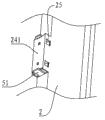
As Fig. 4, Fig. 6 and shown in Figure 7, the side 22 of described back cover 2 also is provided with the cover with side 5 that cooperates with described side groove 24.Described cover with side 5 is the L shape, the outer surface of described cover with side 5 surrounds described side groove 24, described cover with side 5 head, end are provided with buckle 51, the last lower wall of described side groove 24 hollows out to cooperate described buckle 51, described buckle 51 is connected with described madial wall 241, prevents that described cover with side 5 from coming off, thereby, described cover with side 5 has blocked described second screw 4, increases the aesthetic feeling of overall structure outward appearance.
As Fig. 5, Fig. 6 and shown in Figure 7, the described back cover 2 and the described main part 11 that are positioned at described side groove 24 are respectively arranged with for horizontal location part 25, the Vertical location spare 15 of locating described cover with side 5.Described horizontal location part 25 and described Vertical location spare 15 start part by the material of position and form, make simple and economical with materials, the described cover with side 5 in described horizontal location part 25 location inserts the degree of depth of described side groove 24, the direction of the described cover with side 5 vertical described back covers 2 in described Vertical location spare 15 location guarantees that the outer surface of described cover with side 5 surrounds described side groove 24.
As Fig. 4 and shown in Figure 6, described cover with side 5 is provided with hasp 52, and described hasp 52 makes things convenient for the user to dismantle described cover with side 5.
According to above-mentioned technological scheme, described hanger 1 adopts metal folding design cleverly, make described main part 11 and described bending part 12 tightly surround the described back cover 2 of television set, described hanger 1 easy moulding and reliable in quality, by described first screw 3 described hanger 1 is fixed on the wall, by described second screw, 4 side direction locking described hanger 1 is connected with described back cover 2, reasonably avoided the back to beat the shared space of screw and assembling difficult problem, described cover with side 5 designs by seizing type, described second screw 4 is covered, avoid influencing the television set overall appearance.
Below only be preferred embodiment of the present utility model, not in order to limiting the utility model, all any modifications of within spirit of the present utility model and principle, doing, be equal to and replace and improvement etc., all should be included within the protection domain of the present utility model.