The utility model content
The purpose of this utility model is to provide a kind of magnetic force connecting electronic cigarette of Belt connector, reducing the manufacturing cost and use cost of electronic cigarette, and is convenient to dismounting and the replacing of electronic cigarette.
For achieving the above object, the utility model provides a kind of magnetic force connecting electronic cigarette of Belt connector, comprise the soup stick and the power supply bar that connect removably, wherein, described soup stick comprises removable atomizer and is connected connecting this atomizer and power supply bar and with the connector of the power delivery in the power supply bar to atomizer, one end of this connector is connected with atomizer magnetic, and the other end of connector is connected removably with described power supply bar.
Wherein, the link that docks with connector of described atomizer is provided with the first bindiny mechanism, and described the first bindiny mechanism comprises respectively as the first pedestal of first bindiny mechanism's the first electrode with by means of the first insulation sleeve and being installed on the first pedestal and as the first pole of first bindiny mechanism's the second electrode; The link that docks with atomizer of described connector is provided with the second bindiny mechanism, described the second bindiny mechanism comprises as the second pedestal of second bindiny mechanism's the first electrode with by means of the second insulation sleeve and being installed on the second pedestal and as the second pole of second bindiny mechanism's the second electrode, and described the first pedestal and the second pedestal are all whole or local the first magnetic section that is formed with magnetic absorption mutually and the second magnetic section; Described the first magnetic section and the second mutual magnetic absorption of magnetic section connect the first pedestal and the second pedestal and the first pole and the second pole connect.
Wherein, described the first pedestal is tubular, and the first pole is inserted in the middle part of the first pedestal by means of the first insulation sleeve; Described the second pedestal is tubular, and described the second pole is inserted in the middle part of the second pedestal by means of the second insulation sleeve.
Wherein, described the second pole is arranged in the second insulation sleeve, the second insulation sleeve is fixed in the second pedestal, on the second insulation sleeve an end opposite with described the second pole be provided with for described power supply bar in the power supply bar that is electrically connected of electrode on pole, on the power supply bar, pole utilizes a stop collar and is held in the second insulation sleeve, the inside of the second insulation sleeve also is provided with a spring, and the two ends of described spring are connected to respectively pole on the second pole and power supply bar and pole on the second pole and power supply bar is all remained in the state that stretches out the second insulation sleeve; Accordingly, an end that is connected with connector on described power supply bar is provided with under a power supply bar that on pole and described power supply bar, pole connects.
Wherein, described connector has a connector ferrule for fixing described the second bindiny mechanism, this connector ferrule is the cylinder that connects vertically, one end of this connector ferrule is provided with described the second bindiny mechanism, and the other end is with the first bindiny mechanism to insert in it and is connected with described second bindiny mechanism's phase magnetic for described.
Wherein, described atomizer comprises suction tube and is located at the atomising mechanism that is used for storing the tobacco juice cup of tobacco juice in suction tube and is used for the tobacco juice atomizing is changed into smog, the first electrode of this atomising mechanism and the second electrode respectively with the first electrode and second electrode of described the first bindiny mechanism, namely be electrically connected to described the first pole and the first pedestal.
Wherein, described the first pedestal is cylindrical structure, and the one end inserts in described suction tube and atomising mechanism is fixed in suction tube; The other end of the first pedestal expose suction tube outside so that be connected with described second bindiny mechanism's magnetic in suction tube inserts described connector ferrule in the lump; The outer wall tensioner of utilizing described the first pedestal is fixed on the inwall of described suction tube; Extend radially outward on the end sidewalls of described the first pedestal and be formed for the locating flange suitable with the end of described suction tube; Form a snap ring on the inwall of the first pedestal and be used for described the first pole is installed, the first pole utilizes described the first insulation sleeve to be fixed in this snap ring.
Wherein, described suction tube comprises that the inserting paragraph that is connected with described connector is provided with a limited step to revealed section between inserting paragraph and revealed section with being used for inserting in described connector, and inserting paragraph is inserted in described connector and utilized described limited step spacing.
Wherein, described tobacco juice cup comprises for the cup cylinder of storage tobacco juice and is used for the tobacco juice in the cup cylinder is guided to described atomising mechanism so that with the drain assembly of tobacco juice atomizing.
Wherein, whole conductive magnet or the magnetic material of adopting of described the first magnetic section made, but perhaps the part of described the first magnetic section is made by conductive material; Described the second magnetic section adopts conductive magnet or magnetic material to make, but perhaps the part of described the second magnetic section is made by conductive material and formed.
After adopting technique scheme, the magnetic force connecting electronic smoking set of Belt connector of the present utility model has following beneficial effect: at first, atomizer and connector split production, after tobacco juice in atomizer is finished using, only need to change atomizer and connect machine and can keep and to change, saved manufacturing cost and use cost; Secondly, the first bindiny mechanism in atomizer inserts in described connector and is connected with second bindiny mechanism's magnetic in it, and the assembly and disassembly of atomizer and connector are very convenient; Moreover, the second bindiny mechanism be provided with on second pole that can expose all the time the second insulation sleeve outside and power supply bar pole respectively with atomizer and power supply bar on pole butt under corresponding the first electrode and power supply bar, make connector be connected circuit with the power supply bar with described atomizer and be connected reliably.Moreover the bottom of described tobacco juice cup is provided with the drain assembly, utilizes its assembly overnight and liquid storage parts to combine, and its drain is respond well.At last, the inner air duct that forms uniqueness of electronic cigarette, the circulation of air of electronic cigarette and outside is smooth and easy.
Below in conjunction with accompanying drawing, the utility model embodiment is described in further detail.
The specific embodiment
Need to prove, in the situation that do not conflict, embodiment and the feature in embodiment in the application can mutually combine, and below in conjunction with the drawings and specific embodiments, the utility model are described in further detail.
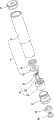
As shown in Fig. 1 to 8, the utility model embodiment provides a kind of magnetic force connecting electronic cigarette of Belt connector, the magnetic force connecting electronic tobacco bale of this Belt connector is drawn together soup stick 90 and power supply bar 95, atomizer 91 and connector 92 that soup stick 90 fits together by pegging graft form, described connector 92 is between atomizer 91 and power supply bar 95, be used for connecting atomizer 91 and power supply bar 95, and the power delivery that power supply bar 95 is interior is to atomizer 91, one end of this connector 92 is connected with atomizer 91 magnetic, and the other end of connector 92 removably is connected with described power supply bar 95.The link that docks with connector 92 of described atomizer 91 is provided with the first bindiny mechanism 5, accordingly, the link that docks with atomizer 91 of described connector 92 is provided with the second bindiny mechanism 6, interconnect by magnetic-adsorption between described atomizer 91 and connector 92 and be integral, atomizer 91 is connected with connector with side's insertion the opposing party inserting mode absorption connection, is as the criterion with direction shown in Figure 1 in the present embodiment.
As shown in Fig. 4 to 5, described atomizer 91 comprises the suction tube 1, atomising device 2, tobacco juice cup 3 of tube structure logical in being, with label not in the suction nozzle cover 4(figure of passage) and be used for the first bindiny mechanism 5 of being connected with connector 92.Described suction nozzle cover 4 and the first bindiny mechanism 5 are installed on respectively the two ends of suction tube 1, and atomising device 2 and tobacco juice cup 3 are positioned at suction tube 1.Suction tube 1 comprises the revealed section 11 that exposes described connector 92 outsides and is used for inserting inserting paragraph 12 in described connector 92, be provided with the end termination that limited step 13, the first bindiny mechanisms 5 are located at the inserting paragraph 12 of connector 92 between revealed section 11 and inserting paragraph 12.Suction tube 1 inside is provided with the passage that connects vertically.
Described the first bindiny mechanism 5 comprises as the first pedestal 51 of first bindiny mechanism's the first electrode, as the first pole 52 and first insulation sleeve 53 of first bindiny mechanism's the second electrode, and described the first pole 52 middle parts are provided with the passage of axial perforation.The first pole 52 is sheathed to be fixed in described the first insulation sleeve 53, and the first pole 52 is inserted in the middle part of the first pedestal 51 by means of the first insulation sleeve 53, and the first pole 52 and described the first insulation sleeve 53 form the first pole assembly.In this enforcement, described the first pedestal 51 and described the first pole 52 are respectively as the first electrode (as negative electrode) and second electrode (as positive electrode) of the first bindiny mechanism 5.Described the first pedestal 51 adopt can by the magnetic material of magnet adsorption for example ferrous material make, it inserts in suction tube 1 and connects with described atomising device 2.The inwall of the shape of the first pedestal 51 and described suction tube 1 is suitable, and it is tube structure, and it utilizes the outer wall tensioner to be fixed on the inwall of described atomizer 91 links; Extend radially outward on the end sidewalls of described the first pedestal 51 and be formed for the locating flange suitable with the end of described suction tube 1; Form a snap ring on the inwall of the first pedestal 51 and utilize described the first insulation sleeve 53 to be fixed in this snap ring for described the first pole 52, the first poles 52 are installed, the middle part of the first pole 52 is provided with the passage of axial perforation.
Described atomising device 2 comprises atomising mechanism 21, atomising mechanism control circuit board 22 and is used for accommodating and fixes the wiring board holder 23 of this atomising mechanism control circuit board 22, in the present embodiment, atomising mechanism 21 is located in suction tube 1, and atomising mechanism control circuit board 22 and wiring board holder 23 are located in described power supply bar 95, and atomising mechanism control circuit board 22 is provided with the minitype pneumatic switch and makes atomising mechanism 21 startup work with the control circuit conducting.
Described atomising mechanism 21 is used for the tobacco juice atomizing is transformed into smog, the atomizing seat 213 that it comprises heating wire 211, is used for the filamentary member 212 that absorbs tobacco juice and support this heating wire 211 and is used for supporting described filamentary member 212, described heating wire 211 is wound on described filamentary member 212, filamentary member 212 can absorb water and retaining as sponge, can or have imbibition and make every material such as the cotton material of fluidity energy by glass fibre.In this example, this filamentary member 212 is accommodating to be fixed in described atomizing seat 213, and the two ends of heating wire 211 pass atomizing seat 213 and are electrically connected to positive electrode and negative electrode in described connector 92.described atomizing seat 213 is roughly cylindrical, its inside is provided be used to the draw-in groove that clamps described filamentary member 212, its middle part is provided with the passage of axial perforation, the both sides of this passage also are provided with the through wires hole that the described heating wire of confession passes that is used for that connects vertically, atomizing seat 213 utilizes the sidewall tensioner to be fixed on the inwall of described suction tube 1, the other end that is provided with draw-in groove and described first pedestal 51 of atomizing seat 213 connect and are fixed in suction tube 1 by described the first pedestal 51, and make described filamentary member 212 and described tobacco juice cup 3 connect so that filamentary member 212 absorbs the tobacco juice that is directed flowing out in the tobacco juice cup 3.
Described tobacco juice cup 3 comprises for the cup cylinder 31 of storage tobacco juice and is used for the tobacco juices in cup cylinder 31 are guided to described atomising mechanism 21 so that with the drain assembly of tobacco juice atomizing.Described cup cylinder 31 is an end opening and the cup of other end sealing, and its cross section is annular 31, itself and described suction tube 1 formation one.Described drain assembly comprises the liquid storage parts 33 of being located at glass oil removal parts 32 of 31 bottom and fitting in oil removal parts 32 bottoms.Described oil removal parts 32 are provided with several delivery holes, and the uninterrupted of tobacco juice is controlled by size and the quantity of described delivery hole.Oil removal parts 31 are close to the openend of cup cylinder 31 with the sealing tobacco juice.Liquid storage parts 33 also can absorb water and retaining as sponge, it adopts resistant to elevated temperatures and has imbibition and make every the material of fluidity energy, liquid storage parts 33 utilize its sidewall tensioner to be fixed on the inwall of described suction tube 1, the one end is close on described oil removal parts 32 described oil removal parts 32 to be fixed in the bottom of cup cylinder 31, and the other end of liquid storage parts 33 and described filamentary member 212 connect.Tobacco juice from cup cylinder 31 interior permeate and absorbs and be stored in liquid storage parts 32 through liquid islocation plate 31 also further tobacco juice is atomized for described heating wire 211 by described filamentary member 212 absorptions.
As Figure 6 and Figure 7, described connector 92 integral body are tubular, and it comprises connector sleeve 921, and an end that is connected with described atomizer 91 on connector sleeve 921 is provided with the second bindiny mechanism 6 that is connected with described the first bindiny mechanism 5.Described the second bindiny mechanism 6 comprises as the second pedestal 61 of second bindiny mechanism's the first electrode, is located at the second pole assembly 62 and permanent magnet 922 in the second pedestal 61.The second pole assembly 62 inserts in the second pedestal 61 and simultaneously permanent magnet 922 is fixed in the second pedestal 61.
Described the second pedestal 61 is the cylindrical structure of hollow, and the one end inserts the inside of described connector sleeve 921 and is fixed in connector sleeve 921, and the other end is provided with the male connection that is connected for described power supply bar 95.Described second level column assembly 62 comprises the second insulation sleeve 621, be located at the second insulation sleeve 621 two ends and stretch out all the time the second pole 622 of the second insulation sleeve 621 outsides and the power supply bar on pole 623, be located at the second insulation sleeve 621 inner and its two ends and be connected to respectively on described the second pole 622 and power supply bar on pole 623 end of being located at described the second insulation sleeve 621 so that stretch out all the time both that pole 623 on the outer spring 624 of the second insulation sleeve 621, described power supply bar utilizes a stop collar 625.On described the second pole 622 and power supply bar, the middle part of pole 623 is equipped with the passage of axial perforation, and it is as second bindiny mechanism's the second electrode.Form the second pole assembly 62 by pole 623, described spring 624 and described stop collar 625 on described the second insulation sleeve 621, the second pole 622, power supply bar, reliable with the connection of described atomizer 91 and power supply bar 95 respectively to guarantee connector 92.
Described the second insulation sleeve 621 roughly is the cup shape, it adopts the insulation material to make, comprise sidewall, roof and surrounded the inner chamber that is used for accommodating described spring 624 that forms by sidewall and diapire, an end relative with its roof on the second insulation sleeve 621 is openend, also is provided with the second pole column hole of stretching out for described the second pole 622 (in figure not label) on described roof.Extend radially outward out a flange (in figure not label) on described roof, the second insulation sleeve 621 passes described permanent magnet and inserts in described the second pedestal 61 and utilize its outer wall and the second pedestal tensioner to fix, and utilizes simultaneously described flange that described permanent magnet 922 is fixed on described the second pedestal 61.
Described stop collar 625 roughly is cylindrical shape, its middle part is provided with axial pass-through holes (in figure not label), on its end sidewalls radially phase epitaxy stretch a defining flange arranged, stop collar 625 inserts in described the second insulation sleeve 621 and utilizes its sidewall tensioner on the intracavity sidewall of the second insulation sleeve 621, and utilizes described defining flange spacing.Described through hole stretches out stop collar 625 outsides for pole 623 on described power supply bar and namely stretches out the second insulation sleeve 621 outsides.
Described permanent magnet 922 is the torus structure, is provided with middle through hole (in figure not label) in this permanent magnet 922 and passes for described the second insulation sleeve 621, and permanent magnet 922 is fixed in described the second bindiny mechanism 6.
Described the first pedestal 51 is whole or local forms the first magnetic section, and in the present embodiment, the first pedestal 51 integral body are as the first magnetic section.Whole or the local formation of described the second pedestal 61 can with the second magnetic section of the first corresponding magnetic absorption of magnetic section.Locate better and fix when the first pedestal 51 on described atomizer docks for ease of the second pedestal 61 on connector, the first pedestal 51 can adopt conductive magnet or magnetic material to make, described magnetic material can adopt ferrous material, thereby consisting of one first magnetic section by the first pedestal 51, can be also the absolute construction spare of being made by conductive magnet or magnetic material to be set consist of described the first magnetic section on the first pedestal 51; Perhaps but the part of described the first magnetic section is made by conductive material.And correspondingly, the second pedestal 61 also can adopt conductive magnet or magnetic material to make, thereby by the second seated body 61 integral body consist of can with the first pedestal 51 on the second magnetic section of the first corresponding magnetic absorption of magnetic section, can be also to consist of described the second magnetic section at the independently structural member that the second interior setting of pedestal 61 is made by conductive magnet or magnetic material, but perhaps the part of described the second magnetic section be made by conductive material.In the present embodiment, namely adopted the magnet of independent design or permanent magnet 922 that magnetic material is made to be used as the second magnetic section.Therefore, the matching relationship of the first magnetic section and the second magnetic section can be magnet and magnet, magnet and magnetic material or magnetic material and magnet.
as shown in Figure 3, when the first bindiny mechanism 5 of atomizer 91 insert in the connector ferrule 921 of connectors 92 and insert put in place after, at this moment, one end of the first pedestal 51 and permanent magnet 922 of described the second bindiny mechanism 6 connects or approach, magnetic attraction due to permanent magnet 922, the first pedestal 51 is firmly held by permanent magnet 922 and can not break away from easily connector 91, the second pole 622 of the second bindiny mechanism 6 is subjected to the supporting of end face of the first pole 52 of the first bindiny mechanism 5 and the elastic force that overcomes spring 624 bounces back a little and is being closely against under the effect of spring 624 on the first pole 52, guarantee that the first pole 52 contacts well with the second pole 622, and the sidewall of the first pedestal 51 and the inwall of connector ferrule 921 are that the border contacts and realizes conduction, namely realize thus the corresponding connection of circuit with connector 92 internal circuits of atomizer 91.
As shown in Figure 8, described power supply bar 95 roughly is tubular, its end that is connected with described connector 92 is provided with the female adapter 951 that matches with described male connection, this female adapter 951 inside be provided with one with described power supply bar on pole 623 connect with the power supply bar of turning circuit under pole 952, under described power supply bar, pole 952 utilizes an insulation sleeve 953 to be fixed in described female adapter 951; Under the power supply bar, pole 952 middle parts are provided with the passage of axial perforation.Under described female adapter 951 and power supply bar, pole 952 is respectively as the first electrode and second electrode of power supply bar 95.Power supply bar 95 internal-internals are provided with battery 955 parts such as grade.The first electrode of battery 955 and the second electrode are electrically connected to pole 952 under female adapter 951 and power supply bar respectively.The other end of described power supply bar 95 also is provided with capping 956, and capping 956 is provided with indicator lamp and air admission hole (not indicating in figure).
In addition, as shown in Figure 3, extraneous air enters in power supply bar 95 from the air admission hole in the capping 956 of described power supply bar bottom, respectively under the power supply bar on pole 952 and power supply bar the passage of pole 623 enter in the second insulation sleeve 621, then continuation enters in atomizer 91 through the passage of the second pole 622 and the first pole 52 respectively, passage in atomizing seat 213 and the passage in suction tube 1 again, finally flowed out outside soup stick 90 by the passage on suction nozzle cover 4, make the inner air duct that forms uniqueness of electronic cigarette, the circulation of air of electronic cigarette and outside is smooth and easy.Certainly, extraneous air also can be directly passage on the suction nozzle cover 4 enter in atomizer 91.
Although illustrated and described embodiment of the present utility model, need to prove, in the situation that do not conflict, embodiment and the feature in embodiment in the application can mutually combine, for the ordinary skill in the art, be appreciated that in the situation that do not break away from principle of the present utility model and spirit can be carried out multiple variation, modification, replacement and modification to these embodiment, scope of the present utility model is limited by claims and equivalency range thereof.