CN202990808U - Window curtain - Google Patents
Window curtain Download PDFInfo
- Publication number
- CN202990808U CN202990808U CN2012204143123U CN201220414312U CN202990808U CN 202990808 U CN202990808 U CN 202990808U CN 2012204143123 U CN2012204143123 U CN 2012204143123U CN 201220414312 U CN201220414312 U CN 201220414312U CN 202990808 U CN202990808 U CN 202990808U
- Authority
- CN
- China
- Prior art keywords
- stay cord
- pressure
- curtain
- lower rail
- take
- Prior art date
- Legal status (The legal status is an assumption and is not a legal conclusion. Google has not performed a legal analysis and makes no representation as to the accuracy of the status listed.)
- Expired - Fee Related
Links
- NJPPVKZQTLUDBO-UHFFFAOYSA-N novaluron Chemical compound C1=C(Cl)C(OC(F)(F)C(OC(F)(F)F)F)=CC=C1NC(=O)NC(=O)C1=C(F)C=CC=C1F NJPPVKZQTLUDBO-UHFFFAOYSA-N 0.000 claims description 17
- 239000012634 fragment Substances 0.000 claims description 12
- 230000004308 accommodation Effects 0.000 claims description 9
- 230000005540 biological transmission Effects 0.000 claims description 6
- 230000015572 biosynthetic process Effects 0.000 claims description 4
- 230000000694 effects Effects 0.000 description 5
- 239000012141 concentrate Substances 0.000 description 2
- 238000005034 decoration Methods 0.000 description 2
- 238000010586 diagram Methods 0.000 description 2
- 238000005516 engineering process Methods 0.000 description 2
- 238000000034 method Methods 0.000 description 2
- 230000002265 prevention Effects 0.000 description 2
- 230000007613 environmental effect Effects 0.000 description 1
- 238000012856 packing Methods 0.000 description 1
- 238000011084 recovery Methods 0.000 description 1
- 238000004804 winding Methods 0.000 description 1
Images


Classifications
-
- E—FIXED CONSTRUCTIONS
- E06—DOORS, WINDOWS, SHUTTERS, OR ROLLER BLINDS IN GENERAL; LADDERS
- E06B—FIXED OR MOVABLE CLOSURES FOR OPENINGS IN BUILDINGS, VEHICLES, FENCES OR LIKE ENCLOSURES IN GENERAL, e.g. DOORS, WINDOWS, BLINDS, GATES
- E06B9/00—Screening or protective devices for wall or similar openings, with or without operating or securing mechanisms; Closures of similar construction
- E06B9/24—Screens or other constructions affording protection against light, especially against sunshine; Similar screens for privacy or appearance; Slat blinds
- E06B9/26—Lamellar or like blinds, e.g. venetian blinds
- E06B9/262—Lamellar or like blinds, e.g. venetian blinds with flexibly-interconnected horizontal or vertical strips; Concertina blinds, i.e. upwardly folding flexible screens
- E06B2009/2625—Pleated screens, e.g. concertina- or accordion-like
-
- E—FIXED CONSTRUCTIONS
- E06—DOORS, WINDOWS, SHUTTERS, OR ROLLER BLINDS IN GENERAL; LADDERS
- E06B—FIXED OR MOVABLE CLOSURES FOR OPENINGS IN BUILDINGS, VEHICLES, FENCES OR LIKE ENCLOSURES IN GENERAL, e.g. DOORS, WINDOWS, BLINDS, GATES
- E06B9/00—Screening or protective devices for wall or similar openings, with or without operating or securing mechanisms; Closures of similar construction
- E06B9/24—Screens or other constructions affording protection against light, especially against sunshine; Similar screens for privacy or appearance; Slat blinds
- E06B9/26—Lamellar or like blinds, e.g. venetian blinds
- E06B9/28—Lamellar or like blinds, e.g. venetian blinds with horizontal lamellae, e.g. non-liftable
- E06B9/30—Lamellar or like blinds, e.g. venetian blinds with horizontal lamellae, e.g. non-liftable liftable
- E06B9/32—Operating, guiding, or securing devices therefor
- E06B9/322—Details of operating devices, e.g. pulleys, brakes, spring drums, drives
- E06B2009/3222—Cordless, i.e. user interface without cords
Landscapes
- Engineering & Computer Science (AREA)
- Structural Engineering (AREA)
- Architecture (AREA)
- Civil Engineering (AREA)
- Blinds (AREA)
- Curtains And Furnishings For Windows Or Doors (AREA)
Abstract
A curtain comprises an upper rail, a curtain sheet arranged below the upper rail, a lower rail arranged below the curtain sheet, a pressing block which is arranged in the lower rail and protrudes out, a first pressing device and a second pressing device which are arranged at intervals on the inner side of the lower rail and are respectively contacted with the pressing block, and a wire collecting device which is arranged in the lower rail and is connected between the first pressing device and the second pressing device; the first rope-collecting piece and the second rope-collecting piece which respectively penetrate and extend two sides of the curtain sheet penetrate into the rope-collecting device of the lower rail, when a user presses the pressing block of the lower rail, the lower rail is simultaneously pulled to move upwards and downwards, the first rope-collecting piece and the second rope-collecting piece are utilized to enable the curtain sheet to be wound upwards or unfolded downwards, and the first rope-collecting piece and the second rope-collecting piece are collected in the lower rail, so that the danger of accidents caused by the fact that the first rope-collecting piece and the second rope-collecting piece are exposed when the child plays.
Description
Technical field
The utility model relates to a kind of curtain, relates in particular to a kind of curtain of built-in take-up rope.
Background technology
See on the market and have now the Window curtain structure of multiple pattern, for example: sun blind, hundred folding casement curtains, Roman window curtain ... Deng, it is mainly to be installed at home the place such as door and window, in order to reaching the function of shielded from sunlight and decoration, and according to different customers' user demand.
general curtain generally can be divided into and utilizes stay cord to rise or descend and control it and furl and launch action, see also as the U.S. the 7th, 373, 10 structures of curtain shown in No. 965, as Fig. 1, Fig. 2, it mainly generally includes pedestal 11, gauge tap 12 and stay cord group 13, it is the design that utilizes each stay cord 131 to concentrate to stretch through out keeper open-work (scheming not shown) and pressing piece 121 through holes (scheming not shown) of pedestal 11 bottom perforateds (scheming not shown) and gauge tap 12, make each stay cord 131 bottoms can concentrate the position below pedestal 11, and this single gauge tap 12 of mat is controlled the active state of each stay cord 131, in curtain 10 coiling process, the user needs to press on the other hand the pressing piece 121 of gauge tap 12, pull simultaneously the bottom of each stay cord 131 downwards with another hand again, that could once complete curtain 10 furls operation (as Fig. 3), but after curtain 10 furls, stay cord 131 presents long length, stay cord 131 is without furling or hiding and design, easily as ludo companion toy, more can lead to the peril of winding.
The utility model content
The utility model will solve the curtain coiling stay cord and expose the problem that causes child's Environmental security, and for this reason, the utility model provides a curtain, and wish is during with curtain coiling, and stay cord furls that to be seated in lower rail inner.
For reaching the purpose of aforementioned creation, the technical solution adopted in the utility model is to provide a kind of curtain, and described curtain comprises:
Rail on one;
One curtain sheet is arranged on below described upper rail, and described curtain sheet is provided with one first stay cord spare and one second stay cord spare;
Once rail, be arranged on below described curtain sheet, and the side in the middle of described lower rail is provided with a slotted eye;
One pressure is pressed piece, is arranged on described lower rail inside and protrudes out described slotted eye;
One first pressure presses device and one second pressure is pressed device, is disposed on described lower rail inboard, and described the first pressure touches by piece with described pressure respectively by device by device and described the second pressure; And
One take-up, corresponding described slotted eye also is arranged on described first of described lower rail inside and presses to press between installing by device and described second and be connected, penetrate respectively and fix the lower end of described upper rail by an end of described the first stay cord spare and described the second stay cord spare, and the inside of the described curtain sheet of relative another end serial connection, described lower rail, and enter described take-up interior bonds by device and described the second pressure by device by described the first pressure respectively.
Further, curtain described in the utility model, wherein, described pressure has a pressure that protrudes out described slotted eye by end by piece, and described pressure is extended and is convexly equipped with in each end respectively with described first to two sides respectively by the end opposite side and presses to press by device and described second and one first touch end and one second and touch end by what device touched.
Further, curtain described in the utility model, wherein, described take-up includes a pedestal and a transmission group, wherein:
Inner one first accommodation space that forms of described pedestal, be provided with the capping that a recessed edge and a correspondence are embedded described recessed edge above described the first accommodation space, be provided with the fixing protruding axle that a tool one is worn groove in described the first accommodation space, high-level installed one first hole of described pedestal one side tool, and another relative side is provided with one second hole that more described the first hole low level arranges;
Described transmission group comprises a take-up pulley and a shell fragment, described take-up pulley central authorities have a room, described room bottom is provided with one second perforating for the fixing protruding axle cross-under of described pedestal, in described take-up pulley outer rim formation one, storage tank reaches storage tank, described shell fragment is arranged on the room inside of described take-up pulley, and a draw-in groove of a described take-up pulley inwall of end grab of described shell fragment, the wearing in groove of the described fixing protruding axle of the other end grab of described shell fragment.
Further, curtain described in the utility model, wherein, described the first pressure has one first body by device, described the first body is provided with two perforation and the inner face corresponding with described the first hole and is provided with two corresponding grooves, described the first body inside is provided with one first pressing piece, described the first pressing piece outboard end and described first touches end and touches, and be provided with 2 two through holes corresponding to perforation with described the first body, and two projections of respectively corresponding described two grooves, and first elastic component that is located between described the first body and described the first pressing piece.
Further, curtain described in the utility model, wherein, described the second pressure has one second body by device, described the second body is provided with two perforation and the inner face corresponding with described the second hole and is provided with two corresponding grooves, described the second body inside is provided with one second pressing piece, described the second pressing piece outboard end and described second touches end and touches, and be provided with 2 two through holes corresponding to perforation with described the second body, and two projections of respectively corresponding described two grooves, and second elastic component that is located between described the second body and described the second pressing piece.
Further, curtain described in the utility model, wherein, described upper rail is formed with one first lacing hole and one second lacing hole that supplies described the first stay cord spare and described the second stay cord spare to lock and run through the bottom.
Further, curtain described in the utility model, wherein, described lower rail forms one three lacing hole and one four lacing hole that arrange and supply described first stay cord spare and described second stay cord spare stretch through corresponding to described the first lacing hole and described the second lacing hole.
Further, curtain described in the utility model, wherein, described lower rail inside be provided with symmetrical described take-up two sides and with described the 3rd lacing hole and described the 4th corresponding setting of lacing hole and for described the first stay cord spare and described the second stay cord spare around one first roller set of stretching and one second roller set.
Utilize technique scheme, the utility model has following advantages compared to prior art:
The utility model utilizes described the first wire rope handling spare, the second wire rope handling spare to wear described curtain sheet by described upper rail string respectively and described lower rail is inner, when making curtain coiling, described the first stay cord spare, described the second stay cord spare are collected in the take-up of described lower rail, play to play with the prevention child and pull the danger that each stay cord spare causes personal accident.
Below in conjunction with the drawings and specific embodiments, the utility model is described in detail, but not as to restriction of the present utility model.
Description of drawings
Fig. 1 is existing curtain schematic perspective view;
Fig. 2 is the lateral view of existing curtain;
Fig. 3 is pressing and the schematic diagram of curtain coiling for existing curtain gauge tap;
Fig. 4 is expansion schematic perspective view of the present utility model;
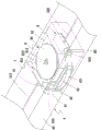
Fig. 5 is that the utility model take-up and first, second pressure arrange lower rail schematic diagram by device;
Fig. 6 is that the utility model take-up and first, second are pressed by the device three-dimensional exploded view;
Fig. 7 is that the utility model the first pressure is pressed illustrative view by device;
Fig. 8 is that the utility model the first pressure is discharged illustrative view by device;
Fig. 9 is that the utility model second is pressed by the device illustrative view;
Figure 10 is the schematic perspective view that furls of the present utility model.
The specific embodiment
Below utilize specific embodiment to coordinate appended accompanying drawing to illustrate in detail, when the effect that is easier to understand the purpose of this utility model, technology contents, characteristics and reaches.
As shown in Figure 4, the utility model provides a kind of curtain, and described curtain 2 includes:
On one, rail 3, and described upper rail 3 forms one first lacing hole 31 and one second lacing hole 32;
Once rail 4, described lower rail 4 is one to be disposed on rail 3 belows, described lower rail 4 is one to have the microscler rail chair 40 of a putting groove 41, and formation and one three lacing hole 42 and one four lacing hole 43 of described the first lacing hole 31 with the second corresponding setting of lacing hole 32, and a side of described putting groove 41 is provided with a slotted eye 44;
One presses and press piece 45, and described pressure is arranged on described lower rail 4 inside by piece 45, has a pressure that protrudes out described slotted eye 44 by end 451, and described pressure is extended and is convexly equipped with one first in each end to two sides respectively by end 451 opposite sides and touches end 452 and 1 second and touch and hold 453;
one folding curtain sheet 5, be arranged on 4, described upper rail 3 and described lower rail, described curtain sheet 5 is provided with one first stay cord spare 51 and one second stay cord spare 52, and a plurality of the first through holes 53 and the second through hole 54 that supply described the first stay cord spare 51 and the second stay cord spare 52 to stretch through respectively and arrange, the first end 511 of described the first stay cord spare 51 and the first end 521 of the second stay cord spare 52 penetrate respectively the first lacing hole 31 and second lacing hole 32 of rail 3 and are fixed on rail 3 inside, and the second relative end 512, 522 stretch through respectively described curtain sheet 5 those first through holes 53 and those second through holes 54 and wear the 3rd lacing hole 42 and the 4th lacing hole 43 to described lower rail 4, and link setting with described take-up 6,
One take-up 6 as Fig. 5 and shown in Figure 6, is located at described lower rail 4 inner and corresponding with described slotted eye 44, and described take-up 6 includes a pedestal 61 and a transmission group 62, wherein:
Inner one first accommodation space 611 that forms of described pedestal 61, be provided with a tool one in described the first accommodation space 611 and wear the fixing protruding axle 612 of groove 613, described the first accommodation space 611 tops are provided with a recessed edge 614, an and corresponding capping 65 that is embedded described recessed edge 614, described capping 65 is provided with one first perforating 651 that coordinates for described fixing protruding axle 612, high-level installed one first hole 615 of described pedestal 61 1 side tools, another relative side are provided with one second hole 616 that arranges than the first hole 615 low levels;
Described transmission group 62 comprises a take-up pulley 63 and a shell fragment 64, described take-up pulley 63 central authorities have a room 630, room 630 bottoms are provided with one second perforating 631, fixing protruding axle 612 cross-under for described pedestal 61, in described take-up pulley 63 outer rims formation one, storage tank 632 reaches storage tank 633, described shell fragment 64 is arranged on room 630 inside of described take-up pulley 63, and a draw-in groove 634 of end 641 described take-up pulley 63 inwalls of grab of shell fragment 64, the wearing in groove 613 of the described fixing protruding axle 612 of the other end 642 grabs;
one first pressure presses device 7 and one second pressure is pressed device 8, please coordinate Fig. 6 to shown in Figure 8, connect respectively and be located at described take-up 6 two sides, and the first hole 615 of corresponding described pedestal 61 dual-sides and the second hole 616 and adopt one high and one low position and arrange respectively, described the first pressure has one first body 71 by device 7, described the first body 71 is provided with two perforation 711 and the inner face corresponding with described the first hole 615 and is provided with two corresponding grooves 712, described the first body 71 inside are provided with the first pressing piece 72 of a removable and socket, described the first pressing piece 72 outboard ends and first touch end 452 and touch, and be provided with two perforation 711 corresponding two through holes 721 with described the first body 71, reach two projections 722 that align respectively corresponding two grooves 712, so that two projections 722 of the first pressing piece 72 align mobile in the respective grooves 712 of described the first body 71 and engaging, can not come off after making the first pressing piece 72 assembly, and 723 of recesses that are arranged on the first body 71 inside and the first pressing piece 72 are provided with one first elastic component 73, push or discharge start for the first pressing piece 72, described the second pressure has one second body 81 by device 8, described the second body 81 is provided with two perforation 811 and the inner face corresponding with described the second hole 616 and is provided with two corresponding grooves 812, described the second body 81 inside are provided with the second pressing piece 82 of a removable and socket, described the second pressing piece 82 outboard ends and second touch end 453 and touch, and be provided with two perforation 811 corresponding two through holes 821 with the second body 81, reach two projections 822 that align respectively corresponding two grooves 812, so that two projections 822 of the second pressing piece 82 align mobile in the respective grooves 812 of described the second body 81 and engaging, can not come off after making the second pressing piece 82 assembly, and 823 of recesses that are arranged on the second body 81 inside and the second pressing piece 82 are provided with one second elastic component 83, push or discharge start (as Fig. 9) for the second pressing piece 82, the object that described the first elastic component 73 and the second elastic component 83 can be spring or have the telescopic resilience function, the elastic telescopic effect of mat the first elastic component 73 and the second elastic component 83, after making described the first pressing piece 72 and the second pressing piece 82 be pressed, can carry out movable telescopic at the first body 71 and the second body 81 inside, and put or the Brake line for opening for the first stay cord spare 51 and the second stay cord spare 52 simultaneously, and
One first roller set 91 and one second roller set 92, be arranged on the inside of the microscler rail chair 40 of lower rail 4, and symmetrical described take-up 6 two sides and with the 3rd lacing hole 42 and the corresponding setting of the 4th lacing hole 43, for described the first stay cord spare 51 and the second stay cord spare 52 easy effect of stretching when stretching the first roller set 91 and the second roller set 92 respectively.
when the second end 522 of the second end 512 of the first stay cord spare 51 of described curtain sheet 5 and the second stay cord spare 52 penetrates respectively the 3rd lacing hole 42 of lower rail 4 and the 4th lacing hole 43, consult simultaneously Fig. 4, respectively around stretching described the first roller set 91 and the second roller set 92, and press respectively two through holes 721 of two perforation the 711 and first pressing pieces 72 of device 7 first bodies 71 by described the first pressure, second presses two through holes 821 of two perforation the 811 and second pressing pieces 82 of pressing device 8 second bodies 81, reach the first hole 615 and the second hole 616 that pass respectively described take-up 6 pedestals 61, the inside that stretches through respectively at last and be wrapped in the upper storage tank 632 of described take-up pulley 63 and lower storage tank 633 fixes.
when wanting to furl or launching curtain 2 of the present utility model, the user utilizes and presses by the pressure that is convexly equipped with in described lower rail 4 by end 451 and described lower rail 4 is drop-down, described pressure first is pressed by part 72 and the second pressure and is pushed described the first bodies 71 and the second body 81 inside by part 82 by what first of piece 45 touched that end 452 and second touches that end 453 will touch respectively, the mat position forms compressive states at the second elastic component 83 of 81 of the first elastic component 73 of 71 of the first pressing piece 72 and the first bodies and the second pressing piece 82 and the second bodies again, and two perforation 711 that make the first body 71 and the first pressing piece 72 two through hole 721 is corresponding communicates, and two perforation 811 of the second body 81 and the second pressing piece 82 two through hole 821 is corresponding communicates, at this moment, the first stay cord spare 51 and the second stay cord spare 52 do for movable opening the action that stretches under the state of putting, the first stay cord spare 51 and the second stay cord spare 52 pulled respectively stretch through inner at described pedestal 61 and be wrapped in upper storage tank 632 and 633 rotations of lower storage tank of take-up pulley 63, and then packing the described take-up pulley 63 inwall draw-in grooves 634 of grab and described fixing protruding axle 612 are worn the shell fragment 64 of groove 613 respectively, unclasp after curtain sheet 5 reaches required length and press by piece 45, consult simultaneously Fig. 8 and shown in Figure 9, described the first pressing piece 72 is subjected to the first elastic component 73 and the second pressing piece 82 to be subjected to the elastic recovery effect of the second elastic component 83 namely to be back to original position, and with the bore a hole relative inner edge of two through holes 821 of the 811 and second pressing pieces 82 of two perforation 711 that utilize first set body 71 and two of two through holes 721 of the first pressing piece 72 and the second body 81, in order to grip respectively the first stay cord spare 51 and the second stay cord spare 52, to limit the activity of the first stay cord spare 51 and the second stay cord spare 52.Therefore, the pressure that is convexly equipped with according to lower rail 4 on the other hand as the user is during by piece 45, see also shown in Figure 10, namely pull simultaneously lower rail 4 to present to push away, drop-down start, utilize the first stay cord spare 51, the second stay cord spare 52 (consulting simultaneously Fig. 4) that curtain sheet 5 can be formed upwards to furl or the drops down state under, described the first stay cord spare 51 and the second stay cord spare 52 all are collected in the take-up 6 in lower rail 4, reach the prevention child and play and play the function that exposes the first stay cord spare 51, the second stay cord spare 52 and cause the dangerous of personal accident and possess sunlight and decoration.
Certainly; the utility model also can have other various embodiments; in the situation that do not deviate from the utility model spirit and essence thereof; those of ordinary skill in the art work as can make various corresponding changes and distortion according to the utility model, but these corresponding changes and distortion all should belong to the protection domain of the appended claim of the utility model.
Claims (8)
1. a curtain, is characterized in that, described curtain comprises:
Rail on one;
One curtain sheet is arranged on below described upper rail, and described curtain sheet is provided with one first stay cord spare and one second stay cord spare;
Once rail, be arranged on below described curtain sheet, and the side in the middle of described lower rail is provided with a slotted eye;
One pressure is pressed piece, is arranged on described lower rail inside and protrudes out described slotted eye;
One first pressure presses device and one second pressure is pressed device, is disposed on described lower rail inboard, and described the first pressure touches by piece with described pressure respectively by device by device and described the second pressure; And
One take-up, corresponding described slotted eye also is arranged on described first of described lower rail inside and presses to press between installing by device and described second and be connected, penetrate respectively and fix the lower end of described upper rail by an end of described the first stay cord spare and described the second stay cord spare, and the inside of the described curtain sheet of relative another end serial connection, described lower rail, and enter described take-up interior bonds by device and described the second pressure by device by described the first pressure respectively.
2. curtain according to claim 1, it is characterized in that, described pressure has a pressure that protrudes out described slotted eye by end by piece, and described pressure is extended and is convexly equipped with in each end respectively with described first to two sides respectively by the end opposite side and presses to press by device and described second and one first touch end and one second and touch end by what device touched.
3. curtain according to claim 2, is characterized in that, described take-up includes a pedestal and a transmission group, wherein:
Inner one first accommodation space that forms of described pedestal, be provided with the capping that a recessed edge and a correspondence are embedded described recessed edge above described the first accommodation space, be provided with the fixing protruding axle that a tool one is worn groove in described the first accommodation space, high-level installed one first hole of described pedestal one side tool, and another relative side is provided with one second hole that more described the first hole low level arranges;
Described transmission group comprises a take-up pulley and a shell fragment, described take-up pulley central authorities have a room, described room bottom is provided with one second perforating for the fixing protruding axle cross-under of described pedestal, in described take-up pulley outer rim formation one, storage tank reaches storage tank, described shell fragment is arranged on the room inside of described take-up pulley, and a draw-in groove of a described take-up pulley inwall of end grab of described shell fragment, the wearing in groove of the described fixing protruding axle of the other end grab of described shell fragment.
4. curtain according to claim 3, it is characterized in that, described the first pressure has one first body by device, described the first body is provided with two perforation and the inner face corresponding with described the first hole and is provided with two corresponding grooves, described the first body inside is provided with one first pressing piece, described the first pressing piece outboard end and described first touches end and touches, and be provided with 2 two through holes corresponding to perforation with described the first body, and two projections of respectively corresponding described two grooves, and first elastic component that is located between described the first body and described the first pressing piece.
5. curtain according to claim 4, it is characterized in that, described the second pressure has one second body by device, described the second body is provided with two perforation and the inner face corresponding with described the second hole and is provided with two corresponding grooves, described the second body inside is provided with one second pressing piece, described the second pressing piece outboard end and described second touches end and touches, and be provided with 2 two through holes corresponding to perforation with described the second body, and two projections of respectively corresponding described two grooves, and second elastic component that is located between described the second body and described the second pressing piece.
6. curtain according to claim 1, is characterized in that, described upper rail is formed with one first lacing hole and one second lacing hole that supplies described the first stay cord spare and described the second stay cord spare to lock and run through the bottom.
7. curtain according to claim 6, is characterized in that, described lower rail forms one three lacing hole and one four lacing hole that arrange and supply described first stay cord spare and described second stay cord spare stretch through corresponding to described the first lacing hole and described the second lacing hole.
8. curtain according to claim 7, it is characterized in that, described lower rail inside be provided with symmetrical described take-up two sides and with described the 3rd lacing hole and described the 4th corresponding setting of lacing hole and for described the first stay cord spare and described the second stay cord spare around one first roller set of stretching and one second roller set.
Priority Applications (2)
| Application Number | Priority Date | Filing Date | Title |
|---|---|---|---|
| CN2012204143123U CN202990808U (en) | 2012-08-20 | 2012-08-20 | Window curtain |
| US13/777,370 US9140057B2 (en) | 2012-08-20 | 2013-02-26 | Window covering |
Applications Claiming Priority (1)
| Application Number | Priority Date | Filing Date | Title |
|---|---|---|---|
| CN2012204143123U CN202990808U (en) | 2012-08-20 | 2012-08-20 | Window curtain |
Publications (1)
| Publication Number | Publication Date |
|---|---|
| CN202990808U true CN202990808U (en) | 2013-06-12 |
Family
ID=48561999
Family Applications (1)
| Application Number | Title | Priority Date | Filing Date |
|---|---|---|---|
| CN2012204143123U Expired - Fee Related CN202990808U (en) | 2012-08-20 | 2012-08-20 | Window curtain |
Country Status (2)
| Country | Link |
|---|---|
| US (1) | US9140057B2 (en) |
| CN (1) | CN202990808U (en) |
Cited By (3)
| Publication number | Priority date | Publication date | Assignee | Title |
|---|---|---|---|---|
| CN104847244A (en) * | 2014-02-19 | 2015-08-19 | 陈金福 | Curtain body control mechanism of stay rope-free curtain |
| CN105715194A (en) * | 2014-12-05 | 2016-06-29 | 陈金福 | Curtain body positioning mechanism of curtain without pull rope |
| CN105715195A (en) * | 2014-12-05 | 2016-06-29 | 陈金福 | Curtain body positioning mechanism of curtain without pull rope |
Families Citing this family (13)
| Publication number | Priority date | Publication date | Assignee | Title |
|---|---|---|---|---|
| US9314125B2 (en) * | 2011-05-09 | 2016-04-19 | Hunter Douglas Inc. | Manually movable rails for coverings for architectural openings |
| CN203424757U (en) * | 2013-06-21 | 2014-02-12 | 亿丰综合工业股份有限公司 | Curtain positioner |
| US9422766B2 (en) * | 2013-07-17 | 2016-08-23 | Hunter Douglas, Inc. | Handle and brake arrangement for a covering for architectural openings |
| US9708850B2 (en) | 2013-07-17 | 2017-07-18 | Hunter Douglas Inc. | Arrangement for mounting an actuator button onto a rail of a window covering |
| GB2534083B (en) * | 2013-10-01 | 2019-10-16 | Hunter Douglas Ind Bv | Rail for an architectural covering |
| CN203531716U (en) * | 2013-10-15 | 2014-04-09 | 郑立铭 | Improved Curtains |
| USD780479S1 (en) * | 2015-01-05 | 2017-03-07 | Li-Ming Cheng | Window blind |
| US20160245017A1 (en) * | 2015-02-24 | 2016-08-25 | Yao-Tsung Chen | Drive system for a cordless blind |
| TWM522994U (en) * | 2016-01-29 | 2016-06-01 | Ching Feng Home Fashions Co | Control device for folding/unfolding curtain body |
| CN205990871U (en) * | 2016-05-31 | 2017-03-01 | 亿丰综合工业股份有限公司 | Drawstring locking mechanism for curtains |
| EP3409875B1 (en) * | 2017-06-01 | 2025-07-30 | Hunter Douglas Industries B.V. | Venetian blind with a tilt adjuster control mechanism |
| CN108716357B (en) * | 2018-08-06 | 2023-09-15 | 南通理工学院 | Curtain with light shielding and protecting functions |
| AU2020201616B2 (en) * | 2019-03-08 | 2025-08-14 | Levolor Inc. | Bottom rail assembly for a covering for an architectural structure and related assembly methods |
Family Cites Families (4)
| Publication number | Priority date | Publication date | Assignee | Title |
|---|---|---|---|---|
| US7575036B2 (en) * | 2005-02-04 | 2009-08-18 | Li-Ming Cheng | Pulling cord winder for venetian blind |
| US20060196612A1 (en) * | 2005-03-03 | 2006-09-07 | Springs Window Fashions Lp | Bottom up top down cordless shade |
| US7373965B2 (en) * | 2005-04-20 | 2008-05-20 | Li-Ming Cheng | Window shade lift cord apparatus |
| US20080099159A1 (en) * | 2006-10-06 | 2008-05-01 | Delilah Co., Ltd. | Cordless window blind structure |
-
2012
- 2012-08-20 CN CN2012204143123U patent/CN202990808U/en not_active Expired - Fee Related
-
2013
- 2013-02-26 US US13/777,370 patent/US9140057B2/en not_active Expired - Fee Related
Cited By (5)
| Publication number | Priority date | Publication date | Assignee | Title |
|---|---|---|---|---|
| CN104847244A (en) * | 2014-02-19 | 2015-08-19 | 陈金福 | Curtain body control mechanism of stay rope-free curtain |
| CN104847244B (en) * | 2014-02-19 | 2017-06-30 | 陈金福 | The curtain controlling organization of curtain without stretching wire |
| CN105715194A (en) * | 2014-12-05 | 2016-06-29 | 陈金福 | Curtain body positioning mechanism of curtain without pull rope |
| CN105715195A (en) * | 2014-12-05 | 2016-06-29 | 陈金福 | Curtain body positioning mechanism of curtain without pull rope |
| CN105715195B (en) * | 2014-12-05 | 2017-11-14 | 陈金福 | Curtain body positioning mechanism for cordless curtains |
Also Published As
| Publication number | Publication date |
|---|---|
| US9140057B2 (en) | 2015-09-22 |
| US20140048220A1 (en) | 2014-02-20 |
Similar Documents
| Publication | Publication Date | Title |
|---|---|---|
| CN202990808U (en) | Window curtain | |
| CN203531716U (en) | Improved Curtains | |
| US20140069592A1 (en) | Control assembly for cordless window curtains | |
| KR101270204B1 (en) | Blind for safety a handle | |
| US20140216664A1 (en) | Cordless curtain assembly | |
| US20140284006A1 (en) | Safety rope assembly for window curtain | |
| CN101973344B (en) | Internal-locking wire-control folding system | |
| CN204002472U (en) | A kind of indoor double-layer window curtain | |
| CN202144682U (en) | Novel car roof tent | |
| CN201194726Y (en) | Non pull rope window curtain | |
| CN201977512U (en) | Rope-free Roman curtain | |
| CN204100545U (en) | Caster mounting structure of dehumidifier and dehumidifier | |
| CN203128100U (en) | Pulley for taking up or paying off cable for diving robot system | |
| CN202820859U (en) | Drawstring-free curtain construction | |
| CN203802099U (en) | Safe bed guardrail | |
| CN204582539U (en) | Novel pressure shoulder device | |
| CN204299445U (en) | A kind of detachable ladder sub-component | |
| CN204485298U (en) | Foldable slide | |
| CN202060552U (en) | Roman shade without stay rope | |
| CN203113995U (en) | Drawstring-free curtain construction | |
| CN202500389U (en) | Switch cabinet electromagnetic lock protective cover | |
| CN201576811U (en) | Concealed safety socket | |
| CN202723505U (en) | Curtain body linkage rope fixing device | |
| CN204754146U (en) | Novel crawler -type impressed watermark ware | |
| CN102704823A (en) | Novel curtain sheet for roll-up window |
Legal Events
| Date | Code | Title | Description |
|---|---|---|---|
| C14 | Grant of patent or utility model | ||
| GR01 | Patent grant | ||
| CF01 | Termination of patent right due to non-payment of annual fee | ||
| CF01 | Termination of patent right due to non-payment of annual fee |
Granted publication date: 20130612 Termination date: 20160820 |