CN202882861U - Device for fast connecting and locking underwater joints - Google Patents
Device for fast connecting and locking underwater joints Download PDFInfo
- Publication number
- CN202882861U CN202882861U CN201220538994.9U CN201220538994U CN202882861U CN 202882861 U CN202882861 U CN 202882861U CN 201220538994 U CN201220538994 U CN 201220538994U CN 202882861 U CN202882861 U CN 202882861U
- Authority
- CN
- China
- Prior art keywords
- connecting rod
- sleeve
- joint
- assembly
- chute
- Prior art date
- Legal status (The legal status is an assumption and is not a legal conclusion. Google has not performed a legal analysis and makes no representation as to the accuracy of the status listed.)
- Expired - Fee Related
Links
Images


Landscapes
- Quick-Acting Or Multi-Walled Pipe Joints (AREA)
Abstract
本实用新型公开了一种水下接头快速连接锁紧装置,包括上部总成和下部总成两部分,上部总成的顶部设置有端头,端头下端轴心孔套装有丝杠,丝杠向下伸进套筒中,套筒内腔的上段设置有调整块和限位盘;在丝杠的外圆周向上设有卡环,在限位盘的内圆周向上设有卡槽,卡环嵌入到卡槽内;套筒内腔的下段设置有连杆,丝杠的下端与连杆的上端螺纹啮合连接;套筒与连杆外圆表面上三条纵向滑槽滑动连接;连杆的下端外圆的周向上均布有三个卡块,每两个卡块之间形成卡槽;下部总成包括连接座和下连接盘,连接座与连杆的卡块和卡槽配合设置。本实用新型的装置,用于深水中将水下一组(多个)配对接头同时快速连接并锁紧,操作简单,工作可靠。
The utility model discloses a fast connection and locking device for an underwater joint, which comprises two parts, an upper assembly and a lower assembly. A terminal is arranged on the top of the upper assembly, and a lead screw is set in a shaft center hole at the lower end of the end. Extending downwards into the sleeve, the upper part of the inner cavity of the sleeve is provided with an adjustment block and a limit plate; a snap ring is provided upward on the outer circumference of the lead screw, and a card groove is provided upward on the inner circumference of the limit plate, and the snap ring Embedded in the card slot; the lower part of the inner cavity of the sleeve is provided with a connecting rod, and the lower end of the screw is threadedly connected with the upper end of the connecting rod; the sleeve is slidingly connected with three longitudinal chute on the outer surface of the connecting rod; the lower end of the connecting rod Three clamping blocks are evenly distributed on the circumference of the outer circle, and a clamping groove is formed between every two clamping blocks; the lower assembly includes a connecting seat and a lower connecting plate, and the connecting seat is set in cooperation with the clamping blocks and the clamping grooves of the connecting rod. The device of the utility model is used for quickly connecting and locking a group (multiple) of paired joints underwater simultaneously in deep water, and has simple operation and reliable operation.
Description
技术领域 technical field
本实用新型属于石油钻采装备技术领域,涉及一种水下接头快速连接锁紧装置。The utility model belongs to the technical field of oil drilling and production equipment, and relates to a fast connection and locking device for an underwater joint.
背景技术 Background technique
深水中远距离同时安装一组(多个)接头时,需利用一套装置将配对接头快速连接并锁紧,以实现接头管道的连通。安装时,需对接头远程控制准确定位,同时将多个接头快速连接并锁紧,要求连接简单快速,锁紧可靠。When a group (multiple) of joints are installed at a long distance in deep water at the same time, it is necessary to use a set of devices to quickly connect and lock the matching joints to realize the connection of the joint pipes. During installation, it is necessary to remotely control the accurate positioning of the joints, and at the same time quickly connect and lock multiple joints. The connection is required to be simple and fast, and the locking is reliable.
目前尚无专门针对深水中将一组管接头同时连接锁紧的装置。At present, there is no device for simultaneously connecting and locking a group of pipe joints in deep water.
发明内容 Contents of the invention
本实用新型的目的是提供一种水下接头快速连接锁紧装置,解决了现有技术中尚无针对深水中将一组管接头同时连接锁紧的问题。The purpose of the utility model is to provide a fast connection and locking device for underwater joints, which solves the problem in the prior art that a group of pipe joints can be connected and locked simultaneously in deep water.
本实用新型所采用的技术方案是,一种水下接头快速连接锁紧装置,包括上部总成和下部总成两部分,The technical solution adopted by the utility model is, a fast connection and locking device for underwater joints, which includes two parts, an upper assembly and a lower assembly,
在上部总成的顶部设置有端头,端头下端轴心孔套装有丝杠,丝杠向下伸进套筒中,套筒内腔的上段设置有调整块,调整块的纵向中间部位设置有限位盘;在丝杠的外圆周向上设有卡环,在限位盘的内圆周向上设有卡槽,卡环嵌入到卡槽内,并能够在卡槽内旋转;There is a terminal on the top of the upper assembly, and a lead screw is set in the axial hole at the lower end of the terminal. The lead screw extends downward into the sleeve. Limiting disc; a snap ring is provided on the outer circumference of the lead screw, and a card slot is provided on the inner circumference of the limiting disc, and the snap ring is embedded in the card slot and can rotate in the card slot;
套筒内腔的下段设置有连杆,丝杠的下端与连杆的上端通过螺纹啮合连接;在套筒的内圆周向上均布有3个导向销钉,在连杆外圆表面上均布有三条纵向滑槽,每条滑槽分为a段和b段两段滑槽,其中a段滑槽与连杆的轴向有一个角度,b段滑槽平行于连杆的轴线;导向销钉卡入到滑槽内;连杆的下端端头外圆的周向上均布有三个卡块,每两个卡块之间形成卡槽;The lower section of the inner cavity of the sleeve is provided with a connecting rod, and the lower end of the lead screw is connected with the upper end of the connecting rod through threaded engagement; 3 guide pins are uniformly distributed upward on the inner circumference of the sleeve, and evenly distributed on the outer surface of the connecting rod. Three longitudinal chute, each chute is divided into two sections a section and b section chute, wherein a section chute has an angle with the axial direction of the connecting rod, b section chute is parallel to the axis of the connecting rod; into the chute; the outer circle of the lower end of the connecting rod has three clamping blocks evenly distributed in the circumferential direction, and a clamping groove is formed between every two clamping blocks;
下部总成包括连接座和下连接盘,在连接座上部空腔的内侧周向上均布有三个母卡块并形成三个母卡槽,三个母卡块和三个母卡槽分别与连杆的三个卡块和三个卡槽对应配合设置。The lower assembly includes a connection seat and a lower connection plate. Three female blocks are evenly distributed on the inner circumference of the upper cavity of the connection seat and form three female card slots. The three female blocks and the three female card slots are respectively connected with the connection The three clamping blocks and the three clamping slots of the rod are correspondingly matched with each other.
本实用新型的有益效果是:用于深水中将水下一组(多个)配对接头同时快速连接并锁紧,操作简单,工作可靠。The beneficial effect of the utility model is: it is used in deep water to quickly connect and lock a group (multiple) of paired joints underwater at the same time, the operation is simple, and the work is reliable.
附图说明 Description of drawings
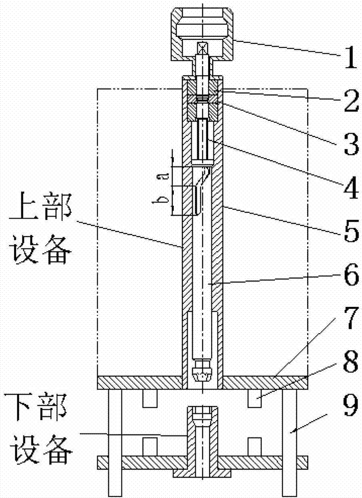
图1为本实用新型的水下接头快速连接锁紧装置的上部总成示意图;Figure 1 is a schematic diagram of the upper assembly of the underwater joint quick connection locking device of the present invention;
图2为本实用新型的水下接头快速连接锁紧装置的下部总成示意图;Fig. 2 is a schematic diagram of the lower assembly of the underwater joint quick connection locking device of the present invention;
图3为图1中的A-A剖视图;Fig. 3 is A-A sectional view among Fig. 1;
图4为图1中的B向视图(不含上连接盘);Figure 4 is a view from direction B in Figure 1 (excluding the upper connection plate);
图5为图2中的C向视图(不含下连接盘);Figure 5 is a C-direction view in Figure 2 (excluding the lower connection plate);
图6为上下两部分总成初始安装时位置示意图;Figure 6 is a schematic diagram of the initial installation of the upper and lower parts of the assembly;
图7为上下两部分总成啮合后的示意图。Fig. 7 is a schematic diagram after the upper and lower parts of the assembly are meshed.
图中,1.端头,2.调整块,3.限位盘,4.丝杠,5.套筒,6.连杆,7.上连接盘,8.接头,9.导向杆,10.连接座,11.接头,12.下连接盘,13.导向孔,14.导向销钉,6-1.卡块,6-2.卡槽,10-1.母卡块,10-2.母卡槽,10-3.上部空腔。In the figure, 1. Terminal, 2. Adjusting block, 3. Limiting plate, 4. Lead screw, 5. Sleeve, 6. Connecting rod, 7. Upper connecting plate, 8. Joint, 9. Guide rod, 10 .Connecting seat, 11. Connector, 12. Lower connecting plate, 13. Guide hole, 14. Guide pin, 6-1. Block, 6-2. Card slot, 10-1. Female block, 10-2. Female card slot, 10-3. Upper cavity.
具体实施方式 Detailed ways
参照图1、图2,本实用新型的水下接头快速连接锁紧装置的结构是:包括上部总成和下部总成两部分。Referring to Fig. 1 and Fig. 2, the structure of the quick connection locking device for the underwater joint of the present invention is: it includes two parts, the upper assembly and the lower assembly.
上部总成主要包括端头1、调整块2、限位盘3、丝杠4、套筒5、连杆6、上连接盘7和导向杆9。The upper assembly mainly includes a
端头1设置在上部总成的顶部,用于对整套上部设备的吊装;丝杠4向下伸进套筒5中,向上伸入端头1内;套筒5内腔的上段设置有调整块2,调整块2的纵向中间位置设置有限位盘3;The
在丝杠4的外圆周向上设有卡环,在限位盘3的内圆周向上设有卡槽,卡环嵌入到卡槽内,并可在卡槽内旋转;由于卡环和卡槽的相互作用,使丝杠4的卡环只能在限位盘3的卡槽内绕其轴向转动而不会产生轴向移动,从而限制了丝杠4的轴向移动;A snap ring is provided on the outer circumference of the
连杆6安装在套筒5内,丝杠4的下端与连杆6的上端通过螺纹啮合连接,当丝杠4转动时,将带动连杆6在套筒5内腔中上下滑动;The connecting
如图3所示,在套筒5的内圆周向上均布有3个导向销钉14,在连杆6外圆表面上均布有三条纵向滑槽,每条滑槽分为a段和b段两段滑槽,如图1所示,其中a段滑槽与连杆6的轴向形成一定的角度,b段滑槽平行于连杆6的轴线;导向销钉14卡入到滑槽内,使滑槽沿着导向销钉14滑动,如图1和图6所示;丝杠4转动时,将带动连杆6沿其轴线方向上下移动,由于导向销钉14的导向作用,在滑槽a段滑过导向销钉14时,连杆6在上下运动的同时,会绕其自身轴线旋转一定的角度;在滑槽b段滑过导向销钉14时,连杆6仅沿其轴线方向上下移动而不再绕其轴线转动;As shown in Figure 3, three guide pins 14 are evenly distributed on the inner circumference of the
如图4所示,连杆6的下端端头的结构是,在连杆6外圆的周向上均布有三个卡块6-1,每两个卡块6-1之间形成卡槽6-2。As shown in Figure 4, the structure of the lower end of the connecting
如图2、图5所示,下部总成包括连接座10和下连接盘12,在连接座10上部空腔10-3的内侧周向上均布有三个母卡块10-1并形成三个母卡槽10-2,与上部装置的连杆6的下端端头上均布的卡块6-1和卡槽6-2配合设置及使用。连接时,连杆6的下端端头上的三个卡块6-1穿过连接座10上的三个母卡槽10-2,并插入到连接座10的上部空腔10-3内,当连杆6绕其轴向旋转一定的角度后,连杆6上的三个卡块6-1与连接座10上的三个母卡块10-1相互啮合,将上部总成锁定在下部总成的连接座10上,即将上部总成和下部总成连接成一体,如图7所示。As shown in Figure 2 and Figure 5, the lower assembly includes a connecting
在上连接盘7的下表面处安装有导向杆9,在下连接盘12上表面对应的位置设有导向孔13,安装时,将导向杆9插入到导向孔13内,来对上部总成的安装进行导向。A
在上连接盘7的下表面处安装有接头8,在下连接盘12的上表面对应的位置设有与接头8对应的配对接头11,利用该装置的上下部总成将两处接头连接到一起并锁紧。A
连杆6下端端头上的卡块6-1可与连杆6做成整体式结构,连接座10上的母卡块10-1可与连接座10做成整体式结构。The block 6-1 on the lower end of the connecting
本实用新型快速连接锁紧装置安装过程是,The installation process of the quick connection locking device of the utility model is as follows:
1)初始状态时,先将需连接到水下的上部设备安装在上部总成上,利用上部总成承载上部设备,如图1所示,将下部总成安装在水下设备上;1) In the initial state, first install the upper equipment that needs to be connected underwater on the upper assembly, and use the upper assembly to carry the upper equipment. As shown in Figure 1, install the lower assembly on the underwater equipment;
2)安装时,利用专用工具夹持上部总成的端头1并下放,当上部总成与下部总成接近到足够近的距离时,将上部总成的导向杆9插入到下部总成对应的导向孔13内,如图6所示,然后将上部总成继续缓慢下放;2) When installing, use a special tool to clamp the
将连杆6的下端端头插入到连接座10的空腔10-3内后,利用专用工具旋转丝杠4,在丝杠4的带动下,连杆6将相对丝杠4向上运动,上部总成随之向下运动,使上连接盘7向下连接盘12靠近;当a段滑槽沿着导向销钉14滑动时,连杆6将沿其轴线转过一定的角度,使连杆6下端端头上的卡块6-1与连接座10上的母卡块10-1相啮合,将上部总成与下部总成连接到一起,如图7所示;After inserting the lower end of the connecting
继续旋转丝杠4,当b段滑槽滑过导向销钉14时,由于导向销钉14的限制,连杆6将相对丝杠4继续上行,但不再绕其轴线转动;连杆6带动上部总成继续向下移动,使上、下连接盘上的配对接头相互连接啮合,并最终在丝杠4和连杆6上的螺纹的作用下将配对接头锁紧。Continue to rotate the
3)脱开接头时,反向旋转丝杠4,上、下连接盘上相互啮合的配对接头将退出啮合并脱离,继续反向旋转丝杠4,使连杆6的下端端头上的卡块6-1与下连接座10上的母卡块10-1退出啮合,连杆6的下端端头将从下连接座10的空腔10-3内退出,使上部总成和下部总成相互分离,从而完成对上部总成,即上部设备的回收。3) When disengaging the joint, reversely rotate the
本实用新型的装置,通过一次操作即可实现对多个接头的同时快速连接和锁紧,操作简便,连接快速,可靠。The device of the utility model can quickly connect and lock multiple joints at the same time through one operation, and is easy to operate, fast and reliable to connect.
Claims (5)
- One kind under water the joint quick connection lock tightly install, it is characterized in that: comprise top assembly and bottom assembly two parts,Termination (1) is arranged on the top of top assembly, lower end, termination (1) axle center hole is set with leading screw (4), leading screw (4) puts in downwards in the sleeve (5), and the epimere of sleeve (5) inner chamber is provided with adjustment block (2), and vertical middle part of adjustment block (2) is provided with position-arresting disk (3); Excircle at leading screw (4) upwards is provided with snap ring, upwards is provided with draw-in groove at the inner periphery of position-arresting disk (3), and snap ring is embedded in the draw-in groove, and can rotate in draw-in groove;The hypomere of sleeve (5) inner chamber is provided with connecting rod (6), and the lower end of leading screw (4) is connected by screw-threaded engagement with the upper end of connecting rod (6); Inner periphery at sleeve (5) upwards is evenly equipped with 3 guide pins (14), be evenly equipped with three vertical chutes at connecting rod (6) outer round surface, every chute is divided into a section and two sections chutes of b section, wherein a section chute and connecting rod (6) axially has an angle, and b section chute is parallel to the axis of connecting rod (6); Guide pin (14) snaps onto in the chute; Termination, the lower end cylindrical of connecting rod (6) upwards be evenly equipped with three fixture blocks (6-1) week, form draw-in groove (6-2) between per two fixture blocks (6-1);The bottom assembly comprises Connection Block (10) and lower terminal pad (12), inner circumferential in Connection Block (10) upper cavity (10-3) is evenly equipped with three master card pieces (10-1) and forms three master card grooves (10-2), three master card pieces (10-1) and three master card grooves (10-2) respectively with connecting rod (6) in three fixture blocks (6-1) and the setting of three draw-in grooves (6-2) corresponding matching.
- 2. the quick connection lock of joint under water according to claim 1 tightly installs, and it is characterized in that: the soffit place of described upper terminal pad (7) is equipped with guide peg (9), is provided with pilot hole (13) in position corresponding to lower terminal pad (12) upper surface.
- 3. the quick connection lock of joint under water according to claim 1 tightly installs, it is characterized in that: the soffit place of described upper terminal pad (7) is equipped with joint (8), is provided with the pairing joint (11) corresponding with joint (8) in the position corresponding to upper surface of lower terminal pad (12).
- 4. the quick connection lock of joint under water according to claim 1 tightly installs, and it is characterized in that: the fixture block (6-1) on described connecting rod (6) termination, lower end is monolithic construction with connecting rod (6).
- 5. the quick connection lock of joint under water according to claim 1 tightly installs, and it is characterized in that: described master card piece (10-1) is monolithic construction with Connection Block (10).
Priority Applications (1)
| Application Number | Priority Date | Filing Date | Title |
|---|---|---|---|
| CN201220538994.9U CN202882861U (en) | 2012-10-18 | 2012-10-18 | Device for fast connecting and locking underwater joints |
Applications Claiming Priority (1)
| Application Number | Priority Date | Filing Date | Title |
|---|---|---|---|
| CN201220538994.9U CN202882861U (en) | 2012-10-18 | 2012-10-18 | Device for fast connecting and locking underwater joints |
Publications (1)
| Publication Number | Publication Date |
|---|---|
| CN202882861U true CN202882861U (en) | 2013-04-17 |
Family
ID=48074301
Family Applications (1)
| Application Number | Title | Priority Date | Filing Date |
|---|---|---|---|
| CN201220538994.9U Expired - Fee Related CN202882861U (en) | 2012-10-18 | 2012-10-18 | Device for fast connecting and locking underwater joints |
Country Status (1)
| Country | Link |
|---|---|
| CN (1) | CN202882861U (en) |
Cited By (2)
| Publication number | Priority date | Publication date | Assignee | Title |
|---|---|---|---|---|
| CN103437739A (en) * | 2013-08-21 | 2013-12-11 | 中国海洋石油总公司 | Locating locking mechanism on installation tool of underwater horizontal manifold connector |
| CN105253764A (en) * | 2015-09-28 | 2016-01-20 | 宝鸡石油机械有限责任公司 | Locking piece type underwater rapid locking device |
-
2012
- 2012-10-18 CN CN201220538994.9U patent/CN202882861U/en not_active Expired - Fee Related
Cited By (3)
| Publication number | Priority date | Publication date | Assignee | Title |
|---|---|---|---|---|
| CN103437739A (en) * | 2013-08-21 | 2013-12-11 | 中国海洋石油总公司 | Locating locking mechanism on installation tool of underwater horizontal manifold connector |
| CN103437739B (en) * | 2013-08-21 | 2016-01-27 | 中国海洋石油总公司 | Location locking mechanism on submerged level manifold connector erecting tools |
| CN105253764A (en) * | 2015-09-28 | 2016-01-20 | 宝鸡石油机械有限责任公司 | Locking piece type underwater rapid locking device |
Similar Documents
| Publication | Publication Date | Title |
|---|---|---|
| CN103465051A (en) | Positioning expansion device | |
| CN205438403U (en) | dilator | |
| CN202882861U (en) | Device for fast connecting and locking underwater joints | |
| CN103899592A (en) | Step ball lock-up hydraulic cylinder | |
| CN104234627B (en) | Casing pipe running device and the method for operation is driven based on top | |
| WO2015175295A1 (en) | Enhanced wellhead clamp type hub connection | |
| CN103015934B (en) | A connecting rod structure with detachable expansion cone | |
| CN103291263B (en) | A kind of hollow allocation discharge control method and device | |
| CN203875664U (en) | Quick replacement tool | |
| CN201736145U (en) | Quick positioning locking mechanism | |
| CN209184152U (en) | Power equipment cable fixture | |
| CN104908306B (en) | Insert clamping mechanism | |
| CN201778670U (en) | Bolt spring combination type riser connector | |
| CN202832272U (en) | Sheet type centralizer convenient to replace | |
| CN203640004U (en) | Rapid mounting structure of faucet sleeve | |
| CN102071882B (en) | Hydraulic sleeve positioner | |
| CN202690006U (en) | Self-sealing well cementing rubber plug assembly device | |
| CN103195391A (en) | Slide sleeve switch closing tool | |
| CN205135489U (en) | Coiled tubing radial drilling commutator | |
| CN210033344U (en) | Hydraulic control type underground releasing device | |
| CN204345085U (en) | A kind of crossbeam link | |
| CN203835296U (en) | Power slip | |
| CN203948067U (en) | Casing head syndeton | |
| CN203626680U (en) | A multifunctional sucker rod fisher | |
| CN204175201U (en) | A connection component of an expansion screen |
Legal Events
| Date | Code | Title | Description |
|---|---|---|---|
| C14 | Grant of patent or utility model | ||
| GR01 | Patent grant | ||
| CF01 | Termination of patent right due to non-payment of annual fee |
Granted publication date: 20130417 Termination date: 20211018 |
|
| CF01 | Termination of patent right due to non-payment of annual fee |