CN202791248U - Mounting bracket of vehicular instrument equipment - Google Patents
Mounting bracket of vehicular instrument equipment Download PDFInfo
- Publication number
- CN202791248U CN202791248U CN 201220484753 CN201220484753U CN202791248U CN 202791248 U CN202791248 U CN 202791248U CN 201220484753 CN201220484753 CN 201220484753 CN 201220484753 U CN201220484753 U CN 201220484753U CN 202791248 U CN202791248 U CN 202791248U
- Authority
- CN
- China
- Prior art keywords
- bracket
- base
- wire rope
- side plates
- bottom plate
- Prior art date
- Legal status (The legal status is an assumption and is not a legal conclusion. Google has not performed a legal analysis and makes no representation as to the accuracy of the status listed.)
- Expired - Fee Related
Links
Images


Landscapes
- Vibration Dampers (AREA)
Abstract
本实用新型涉及一种车载仪器设备的安装支架,包括基座,所述基座具有底板和位于三面的侧板,还包括一托架,所述托架由底板和位于底板上的三面侧板构成,所述托架设于基座的内空中,托架的底板、左右侧板以及后侧板分别通过钢丝绳减振器与基座的底板、左右侧板以及后侧板相连,形成悬浮状托架,所述托架上设有固定带,所述基座上设有多个安装固定孔。本实用新型结构简单,质量轻,具有良好的缓冲减振作用,可以有效的保护仪器设备,并具有快速拆装的功能。
The utility model relates to a mounting bracket for vehicle-mounted instruments and equipment, comprising a base, the base has a bottom plate and side plates on three sides, and a bracket, the bracket is composed of the bottom plate and the side plates on three sides of the bottom plate The bracket is arranged in the inner space of the base, and the bottom plate, left and right side plates and rear side plates of the bracket are respectively connected with the bottom plate, left and right side plates and the rear side plate of the base through wire rope shock absorbers to form a suspended state. A bracket, the bracket is provided with a fixing belt, and the base is provided with a plurality of installation and fixing holes. The utility model has the advantages of simple structure, light weight, good buffering and vibration reduction effect, can effectively protect instruments and equipment, and has the function of quick disassembly and assembly.
Description
技术领域 technical field
本实用新型涉及一种仪器设备的车载安装支架,更具体涉及一种具有减震缓冲作用的支架。 The utility model relates to a vehicle-mounted mounting bracket for instruments and equipment, in particular to a bracket with shock-absorbing and buffering functions. the
背景技术 Background technique
随着电子技术的发展,各种仪器设备的重量体积都大大减小,对一些有移动应用需求的精密设备如监护仪、呼吸机等医疗设备,已能很方便的安装在车上实现车载化。目前常用的设备安装方式是将设备直接刚性固定在车上,这种安装方式没有减振效果,而在设备下面加装一层橡胶垫,这种安装方式所起到的减振效果也十分微小。当车子行驶在颠簸路面上时,颠簸的路面会使车子产生强烈的振动,从而车上的设备也会随着强烈振动,不仅对设备的持续工作造成很大影响,而且也会加速设备的损坏。 With the development of electronic technology, the weight and volume of various instruments and equipment have been greatly reduced. For some precision equipment that requires mobile applications, such as monitors, ventilators and other medical equipment, it can be easily installed on the car to achieve vehicle-based . At present, the commonly used equipment installation method is to rigidly fix the equipment directly on the vehicle. This installation method has no vibration reduction effect, and a layer of rubber pad is installed under the equipment. The vibration reduction effect of this installation method is also very small. . When the car is driving on a bumpy road, the bumpy road will cause the car to vibrate strongly, and the equipment on the car will also vibrate strongly, which not only has a great impact on the continuous operation of the equipment, but also accelerates the damage of the equipment . the
实用新型内容 Utility model content
本实用新型所要解决的技术问题是针对目前现有技术的不足,提供一种车载仪器设备的安装支架,它通过设有的悬浮状托架,使得它比其他支架减振效果更好,而且它还有结构可靠、成本低、拆装方便等优点。 The technical problem to be solved by the utility model is to provide a mounting bracket for vehicle-mounted instruments and equipment for the deficiencies of the current prior art. It has a better vibration reduction effect than other brackets through the suspension bracket provided, and it It also has the advantages of reliable structure, low cost, and convenient disassembly and assembly. the
本实用新型为解决上述技术问题采用的技术方案为:一种车载仪器设备的安装支架,包括基座,所述基座具有底板和位于三面的侧板,还包括一托架,所述托架由底板和位于底板上的三面侧板构成,所述托架设于基座的内空中,托架的底板、左右侧板以及后侧板分别通过钢丝绳减振器与基座的底板、左右侧板以及后侧板相连,形成悬浮状托架,所述托架上设有固定带,所述基座上设有多个安装固定孔。 The technical solution adopted by the utility model to solve the above technical problems is: a mounting bracket for vehicle-mounted equipment, including a base, the base has a bottom plate and side plates on three sides, and a bracket, the bracket It is composed of a bottom plate and three side plates located on the bottom plate. The bracket is set in the inner space of the base. The board and the rear side board are connected to form a suspended bracket, the bracket is provided with a fixing belt, and the base is provided with a plurality of installation and fixing holes. the
所述基座的后侧板上部设有向前凸出的悬臂结构,向前凸出的悬臂结构端部安装有钢丝绳减振器。 A cantilever structure protruding forward is provided on the upper part of the rear side plate of the base, and a wire rope shock absorber is installed at the end of the cantilever structure protruding forward. the
所述钢丝绳减振器包括有两个固定装置和多股钢丝弯曲成螺旋状的钢丝绳,两个固定装置分别位于多股钢丝弯曲成螺旋状的钢丝绳的曲面两侧,通过钢丝绳相连,两个固定装置之间留有空间距离。 The wire rope shock absorber includes two fixing devices and a steel wire rope with multiple strands of steel wires bent into a helical shape. Leave a space distance between the devices. the
每个固定装置包含第一固定板和第二固定板,所述第一固定板与第二固定板相向面分别设有供钢丝绳通过的圆弧凹槽,所述第一固定板与第二固定板通过螺栓固定连接,将钢丝绳夹住。 Each fixing device includes a first fixing plate and a second fixing plate, and the opposite faces of the first fixing plate and the second fixing plate are respectively provided with circular arc grooves for the wire rope to pass through, and the first fixing plate and the second fixing plate The plates are fixedly connected by bolts, clamping the wire rope. the
基座底板与托架底板之间设置四个钢丝绳减振器,四个钢丝绳减振器呈矩阵分布或菱形分布。 Four wire rope shock absorbers are arranged between the base bottom plate and the bracket bottom plate, and the four steel wire rope shock absorbers are distributed in a matrix or in a diamond shape. the
基座的左右侧板与托架左右侧板之间,每侧设置至少一个所述钢丝绳减振器。 Between the left and right side plates of the base and the left and right side plates of the bracket, at least one wire rope shock absorber is arranged on each side. the
基座后侧板的悬臂端部与托架后侧板之间设置至少一个所述钢丝绳减振器。 At least one wire rope shock absorber is arranged between the cantilever end of the rear side plate of the base and the rear side plate of the bracket. the
所述托架内侧衬有橡胶垫。 The inside of the bracket is lined with rubber pads. the
所述基座、托架上均设有多个镂空口。 Both the base and the bracket are provided with a plurality of hollow openings. the
采用上述方案,使本实用新型车载仪器设备的安装支架具有以下优点: By adopting the above scheme, the mounting bracket of the vehicle-mounted instrument equipment of the present invention has the following advantages:
1. 与其他支架相比较,本实用新型属于一种新颖的支架结构,结构模式比较简单,包括基座,所述基座具有底板和位于三面的侧板,还包括一托架,所述托架由底板和位于底板上的三面侧板构成,所述托架设于基座的内空中,托架的底板、左右侧板以及后侧板分别通过钢丝绳减振器与基座的底板、左右侧板以及后侧板相连,形成悬浮状托架,使支架的托架与基座之间,在水平方向和垂直方向都具有很好的缓冲减振效果。 1. Compared with other brackets, the utility model belongs to a novel bracket structure, the structure mode is relatively simple, including a base, the base has a bottom plate and side plates on three sides, and also includes a bracket, the bracket The frame is composed of a bottom plate and three side plates located on the bottom plate. The bracket is set in the inner space of the base. The side plates and the rear side plates are connected to form a suspended bracket, so that the space between the bracket of the bracket and the base has good buffering and vibration reduction effects in the horizontal direction and the vertical direction.
2. 所述钢丝绳减振器包括有两个固定装置和多股钢丝弯曲成螺旋状的钢丝绳,两个固定装置分别位于多股钢丝弯曲成螺旋状的钢丝绳的曲面两侧,通过钢丝绳相连,两个固定装置之间留有空间距离,每个固定装置包含第一固定板和第二固定板,所述第一固定板与第二固定板相向面分别设有供钢丝绳通过的圆弧凹槽,所述第一固定板与第二固定板通过螺栓固定连接,将钢丝绳夹住。托架相对基座运动时,该钢丝绳减振器既可径向变形也可轴向变形实现减振,因此,这种钢丝绳减振器比一般弹簧减振器减振效果好。 2. The wire rope shock absorber includes two fixing devices and a steel wire rope with multi-strand steel wires bent into a spiral shape. The two fixing devices are respectively located on both sides of the curved surface of the steel wire rope with multi-strand steel wires bent into a spiral shape. There is a space distance between the two fixing devices, and each fixing device includes a first fixing plate and a second fixing plate, and the opposite surfaces of the first fixing plate and the second fixing plate are respectively provided with circular arc grooves for the passage of steel wire ropes, The first fixing plate and the second fixing plate are fixedly connected by bolts to clamp the wire rope. When the bracket moves relative to the base, the wire rope damper can be deformed radially or axially to achieve vibration reduction. Therefore, the wire rope damper has a better damping effect than the general spring damper. the
3. 所述基座的后侧板上部设有向前凸出的悬臂结构,增大了基座的受力强度,且在托架与基座之间留有足够的空隙,当托架受到来自水平方向的冲击力时,可以避免因托架与基座产生碰撞而导致仪器设备损坏。 3. The upper part of the rear side plate of the base is provided with a cantilever structure protruding forward, which increases the stress strength of the base and leaves enough space between the bracket and the base. When the bracket is subjected to When the impact force comes from the horizontal direction, it can avoid the damage of the instrument and equipment due to the collision between the bracket and the base. the
4.所述托架上设有固定带,设备上方用固定带固定,避免了设备随车身的颠簸而磕碰损坏,松开固定带,即可拆下设备,使其具有了快速拆装的功能。所述基座上设有多个安装固定孔,通过所述安装固定孔用螺钉可以把基座安装在车厢水平或垂直面上。 4. There is a fixing belt on the bracket, and the upper part of the equipment is fixed with the fixing belt, which avoids the bumping and damage of the equipment with the bumps of the vehicle body, and the equipment can be removed by loosening the fixing belt, so that it has the function of quick disassembly and assembly . The base is provided with a plurality of installation and fixing holes, through which the base can be installed on the horizontal or vertical plane of the compartment with screws. the
5.多个镂空口的存在使其质量较轻,节约了支架的成本,并便于设备的线缆穿过。 5. The existence of multiple hollow openings makes the weight lighter, saves the cost of the bracket, and facilitates the passage of equipment cables. the
附图说明 Description of drawings
图1为本实用新型的剖视图; Fig. 1 is the sectional view of the utility model;
图2为图1的A向示意图; Fig. 2 is a schematic diagram of direction A of Fig. 1;
图3为图2的B向示意图; Fig. 3 is a schematic diagram in direction B of Fig. 2;
图4为钢丝绳减振器的结构示意图; Fig. 4 is the structural representation of wire rope shock absorber;
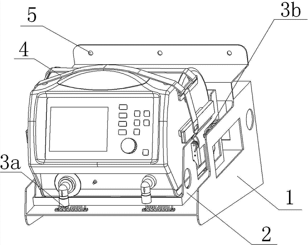
图5为仪器固定在本实用新型上的示意图。 Fig. 5 is a schematic diagram of the instrument being fixed on the utility model.
其中:1为基座,2为托架,3a为第一钢丝绳减振器,3b为第二钢丝绳减振器,3c为第三钢丝绳减振器,4为固定带,5为安装固定孔,6为钢丝绳,7为固定装置。 Among them: 1 is the base, 2 is the bracket, 3a is the first steel wire rope shock absorber, 3b is the second steel wire rope shock absorber, 3c is the third steel wire rope shock absorber, 4 is the fixing belt, 5 is the installation and fixing hole, 6 is a steel wire rope, and 7 is a fixing device. the
具体实施方式 Detailed ways
参见图1至图5,一种车载仪器设备的安装支架,包括基座1,所述基座1具有底板和位于三面的侧板,所述基座1的后侧板上部设有向前凸出的悬臂结构,这种悬臂结构加大了基座1的受力强度,且在所述基座1与所述托架2之间留有足够的空隙,当托架2受到很强的冲击力时,以避免基座1与托架2产生碰撞,而损坏支架。所述基座1的底板位于三面侧板的中下部,还包括一托架2,所述托架2由底板和位于底板上的三面侧板构成,所述托架2设于基座1的内空中,托架2的底板、左右侧板以及后侧板分别通过钢丝绳减振器与基座1的底板、左右侧板以及后侧板相连,形成悬浮状托架,所述托架2的底板前端朝外伸出支座1的底板悬空,这种悬浮状结构可以用来缓冲多个方向的压力。所述钢丝绳减振器包括有两个固定装置7和多股钢丝弯曲成螺旋状的钢丝绳6,两个固定装置7分别位于多股钢丝弯曲成螺旋状的钢丝绳6的曲面两侧,通过钢丝绳6相连,两个固定装置7之间留有空间距离,每个固定装置7包含第一固定板和第二固定板,所述第一固定板与第二固定板相向面分别设有供钢丝绳6通过的圆弧凹槽,所述第一固定板与第二固定板通过螺栓固定连接,将钢丝绳6夹住,所述圆弧凹槽均匀分布,所述第一固定板与第二固定板相向面设有的圆弧凹槽相互对应,所述第一固定板与第二固定板两端均设有固定孔,所述第一固定板上的固定孔与第二固定板上的固定孔相互对应,所述两个固定装置上的固定孔也相互对应,当托架2相对基座1运动时,钢丝绳减振器既可径向变形,也可轴向变形,因此,这种钢丝绳减振器减振效果非常好,通过螺栓把钢丝绳减振器与基座1、托架2固定连接。本实施例的所述基座1底板与托架2底板之间设置四个第一钢丝绳减振器3a四个钢丝绳减振器呈矩阵分布,或者也可呈菱形分布,这样使托架2的平衡性较好,当然,第一钢丝绳减振器3a也可根据实际需要设置为一个或多个;所述基座1左右侧板与托架2左右侧板之间,每侧设置至少一个所述钢丝绳减振器3b,本实施例所述所述第二钢丝绳减振器3b一侧为一个,左右两侧的第二钢丝绳减振器3b相互对应,当然也可根据实际需要在一侧设置两个或多个;所述基座悬臂端部与托架后侧板之间设置至少一个所述钢丝绳减振器3c,本实施例所述第三钢丝绳减振器3c为两个,且两个所述第三钢丝绳减振器3c处在同一水平面,两个所述第三钢丝绳减振器3c在基座底板上的投影与所述四个第一钢丝绳减振器3a相互对应,当然也可根据实际需要设置一个或多个。所述托架2上设有固定带4,所述固定带4可以根据实际需要改变其长度,本实施例所述固定带4包括绑带和搭扣,绑带通过设有的挂环与搭扣连接锁定,使用时把仪器设备放在托架2上,用绑带从设备上绕过,绑带通过挂环与搭扣连接锁定,将仪器设备固定在托架2上,可以避免仪器设备随车身的颠簸而磕碰损坏,松开固定带,即可拆下设备,使其具有了快速拆装的功能。当然也可以使用其他类型的固定带。所述基座1、托架2上均设有多个镂空口,所述镂空口的形状可以是矩形的、圆形的,还可以是其它任意形状,镂空口的数量可以多设几个,来减轻支架的重量,降低了支架的成本,也便于电源线等穿过。所述支座1和托架2两侧立面均设置为阶梯型,也可以减轻支架的重量,节约支架的成本,也便于固定带4固定仪器设备。所述托架2内侧衬还可以设置橡胶垫,减少仪器设备与托架2间的相对滑动,可以更好地保护仪器设备。所述基座1上设有多个安装固定孔5。本实施例中,所述基座1后侧板上、下端各横向设置有一排等间距的安装固定孔5,且两排安装固定孔5相互对应,所述安装固定孔5每排三个,当然也可根据实际需要设置四个或多个,通过所述安装固定孔5用螺钉把支架安装在车厢水平或垂直面上。
Referring to Fig. 1 to Fig. 5, a mounting bracket for vehicle-mounted equipment includes a
上述方案为本实用新型的最优方案,当然,基座只包括底板和一侧板,托架只包括底板和一侧板,在基座底板、后侧板与托架底板、后侧板之间设置所述钢丝绳减振器,其它设置不变的情况下,支架也能达到好的减振效果。 Said scheme is the optimum scheme of the present utility model, certainly, base only comprises base plate and side plate, bracket only comprises base plate and side plate, between base base plate, rear side plate and bracket base plate, rear side plate The steel wire rope shock absorber is arranged between them, and when other settings remain unchanged, the support can also achieve a good vibration damping effect. the
Claims (9)
Priority Applications (1)
| Application Number | Priority Date | Filing Date | Title |
|---|---|---|---|
| CN 201220484753 CN202791248U (en) | 2012-09-21 | 2012-09-21 | Mounting bracket of vehicular instrument equipment |
Applications Claiming Priority (1)
| Application Number | Priority Date | Filing Date | Title |
|---|---|---|---|
| CN 201220484753 CN202791248U (en) | 2012-09-21 | 2012-09-21 | Mounting bracket of vehicular instrument equipment |
Publications (1)
| Publication Number | Publication Date |
|---|---|
| CN202791248U true CN202791248U (en) | 2013-03-13 |
Family
ID=47818510
Family Applications (1)
| Application Number | Title | Priority Date | Filing Date |
|---|---|---|---|
| CN 201220484753 Expired - Fee Related CN202791248U (en) | 2012-09-21 | 2012-09-21 | Mounting bracket of vehicular instrument equipment |
Country Status (1)
| Country | Link |
|---|---|
| CN (1) | CN202791248U (en) |
Cited By (4)
| Publication number | Priority date | Publication date | Assignee | Title |
|---|---|---|---|---|
| CN103322120A (en) * | 2013-03-28 | 2013-09-25 | 苏州优德通力电气有限公司 | Restraining structure for vibration absorption and noise reduction |
| CN103807221A (en) * | 2014-01-03 | 2014-05-21 | 北京怡和嘉业医疗科技有限公司 | Blower unit and ventilator comprising such a blower unit |
| CN107276610A (en) * | 2016-04-07 | 2017-10-20 | 济南比罗茨信息科技有限公司 | A kind of vehicle-mounted WiFi network communication device |
| CN116857322A (en) * | 2023-06-30 | 2023-10-10 | 中元汇吉生物技术股份有限公司 | Vehicle-mounted damping device of mass spectrometer |
-
2012
- 2012-09-21 CN CN 201220484753 patent/CN202791248U/en not_active Expired - Fee Related
Cited By (7)
| Publication number | Priority date | Publication date | Assignee | Title |
|---|---|---|---|---|
| CN103322120A (en) * | 2013-03-28 | 2013-09-25 | 苏州优德通力电气有限公司 | Restraining structure for vibration absorption and noise reduction |
| CN103807221A (en) * | 2014-01-03 | 2014-05-21 | 北京怡和嘉业医疗科技有限公司 | Blower unit and ventilator comprising such a blower unit |
| US10539158B2 (en) | 2014-01-03 | 2020-01-21 | Bmc Medical Co., Ltd. | Blower device and respirator including blower device |
| US11009046B2 (en) | 2014-01-03 | 2021-05-18 | Bmc Medical Co., Ltd. | Blower device and respirator including blower device |
| US12247585B2 (en) | 2014-01-03 | 2025-03-11 | Bmc Medical Co., Ltd. | Blower device and respirator including blower device |
| CN107276610A (en) * | 2016-04-07 | 2017-10-20 | 济南比罗茨信息科技有限公司 | A kind of vehicle-mounted WiFi network communication device |
| CN116857322A (en) * | 2023-06-30 | 2023-10-10 | 中元汇吉生物技术股份有限公司 | Vehicle-mounted damping device of mass spectrometer |
Similar Documents
| Publication | Publication Date | Title |
|---|---|---|
| CN202791248U (en) | Mounting bracket of vehicular instrument equipment | |
| CN205523648U (en) | Engineering vehicle shock absorber | |
| CN203032358U (en) | Automobile power assembly suspension device | |
| CN205365619U (en) | Shock -absorbing structure of locomotive | |
| CN106494210A (en) | A kind of load-carrying vehicle dynamic assembly suspension | |
| CN109578246A (en) | Compressor vibration damper, motor home air conditioner and motor home | |
| CN204915689U (en) | Traction transformer's elastic suspension mounting structure | |
| CN106364414A (en) | Vehicle-mounted navigator with shock absorption device | |
| CN103568808B (en) | Split type spacing support engine suspension assembly | |
| CN109163054A (en) | Quickly dismantled vehicle-mounted photographic goods isolation mounting | |
| CN204196690U (en) | The heat sink arrangement of mounting structure and vehicle | |
| CN210760135U (en) | Rear overhang support of automobile | |
| CN216467236U (en) | Semitrailer suspension assembly | |
| CN201201652Y (en) | Driver's cab with full suspending shock-absorbing device | |
| CN220785433U (en) | Vibration reduction structure of heavy-duty truck battery box | |
| CN105059294A (en) | Elastic suspension mounting structure of traction transformer | |
| CN206493804U (en) | Semi-trailer suspension assembly | |
| CN216761430U (en) | Automobile suspension support | |
| RU2002126325A (en) | DEVICE FOR INSTALLING A CABIN ON THE VEHICLE FRAME | |
| CN205871663U (en) | Rearmounted air suspension girder of bumper shock absorber and assembly thereof | |
| CN213950279U (en) | Elevator damping device | |
| CN217415649U (en) | Adopt compound direction spring absorbing vehicle mobile phone support of multistage | |
| CN205915916U (en) | Electronic compressor bracket | |
| CN205930101U (en) | Automotive suspension based on new cone spring | |
| CN206171156U (en) | A suspension device for vehicle |
Legal Events
| Date | Code | Title | Description |
|---|---|---|---|
| C14 | Grant of patent or utility model | ||
| GR01 | Patent grant | ||
| CF01 | Termination of patent right due to non-payment of annual fee | ||
| CF01 | Termination of patent right due to non-payment of annual fee |
Granted publication date: 20130313 Termination date: 20200921 |