CN202767074U - Pressurized soil anchor reamer - Google Patents
Pressurized soil anchor reamer Download PDFInfo
- Publication number
- CN202767074U CN202767074U CN 201220204187 CN201220204187U CN202767074U CN 202767074 U CN202767074 U CN 202767074U CN 201220204187 CN201220204187 CN 201220204187 CN 201220204187 U CN201220204187 U CN 201220204187U CN 202767074 U CN202767074 U CN 202767074U
- Authority
- CN
- China
- Prior art keywords
- wing
- reaming
- pin
- joint
- reamer
- Prior art date
- Legal status (The legal status is an assumption and is not a legal conclusion. Google has not performed a legal analysis and makes no representation as to the accuracy of the status listed.)
- Expired - Fee Related
Links
Images

Landscapes
- Earth Drilling (AREA)
Abstract
The utility model relates to a pressurized soil anchor reamer. The pressurized soil anchor reamer consists of a drill rod joint, a knife wing and a knife wing control device and is mainly applied to constructions of anchoring, slope protection and sliding slope control in foundation engineering and geological hazard protection engineering. The pressurized soil anchor reamer is characterized in that the reaming knife wing is splayed at the bottom of a hole by a connecting rod mechanism and a push rod, and the splaying angle of the knife wing is limited by a spline limiting device so as to realize reverse reaming. The pressurized soil anchor reamer has a reaming diameter which is 2-3 times of the diameter of the original hole and is low in manufacturing cost, convenient to detach, easy to use and operate and long in service life; and the splaying speed of the knife wing can be controlled only by controlling the drilling pressure.
Description
Technical field
The utility model relates to a kind of engineering construction and creeps into gear, structure anti-floating, anchor tie wall are propped up in the field with deep pit digging pressure-bearing type soil bolt underreamer device.
Background technology
The extensive use of soil bolt technology and develop rapidly are that new way has been opened up in supporting and the reinforcing of the soil body.Along with the development of highrise building and carrying out of national environmental protection engineering and hazards control engineering, excavation of foundation pit is more and more darker, and Reinforcement Works of Rock Slopes is more and more, and is more and more higher to the requirement of the uplift resistance of anchor pole.Therefore improve the anchored force of single soil bolt, significant for reducing construction cost and the expansion scope of application.How its anchored force of Effective Raise is the engineering circles problems of concern always.
The major part that China's anchorage engineering construction adopts is a footpath anchor pole on earth, and diversified anchoring-bolt broaching facility arise at the historic moment.But because the soil layer situation is complicated, these reaming facility generally exist wayward, can't guarantee the reaming quality, the problems such as complicated operation in construction.How to address this problem well and will have certain engineering significance.
Summary of the invention
For the problems referred to above, the utility model provides a kind of mechanical type pressure-bearing reamer, and this reamer adopts spline spacing, and the connecting rod pushing mechanism makes the expansion bed plate wing open at the bottom of the hole and shrink, and is easy to use, simple to operate.
The utility model adopts following technical solution: wing is combined by the wing of two flexible connections, and the wing control device is comprised of the push rod actuator that links to each other with wing and spline stopping means.Because the push rod actuator processing and manufacturing is simple, installation accuracy and machining accuracy are also low than rack pinion structure, can reach the purpose that reduces the reamer cost.
The utility model reamer reaming principle is: when the needs ream operation, transfer at the bottom of the hole expanding end facility, thereby dextrorotation also glides push rod by drilling rod pressurization to make wing open and cut soil layer, wing opens to the maximum diameter of hole when push rod slippage maximum displacement, this moment spline housing internal spline on correct with splined tube on breach on the external splines at same position, thereby since the breach direction just in time with just bore the consistent locking wing that reaches of direction, and make it open to maximum position, apply pull-back force and dextrorotation to drilling rod at last, expand end facility and realize reverse reaming.Because the character of push rod transmission, can control easily the speed of opening of wing by control the pressure of the drill, the pressure of the drill more the pocket knife chord to open speed slower, so be conducive to the stable of wing.After reaming is complete, counter-rotates first drilling tool and the spline housing upper spline separated with breach get back in the former spline, on stop anti-brill at once after carrying drilling rod, wing proposes outside the hole because spring counter-force and hole wall counter-force are regained.
The beneficial effects of the utility model are:
1. owing to having increased linkage, counter bore diameter increases to 2-3 doubly;
2. adopt the spline stopping means, can guarantee that the cornish bit chord reaches maximum angle, and can at the bottom of the hole, realize anti-the expansion;
3. reamer is simple in structure, and machining accuracy and installation accuracy require low, low cost of manufacture.
Description of drawings
Below in conjunction with drawings and Examples the utility model is further specified.
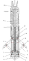
Fig. 1 is structural representation of the present utility model.
Fig. 2 is the structural representation of splined tube in the utility model fishing device.
Among Fig. 1,1. bit body, 2. soket head cap screw, 3. outer tube, 4. reaming wing, 5. splined tube, 6. spline housing, 7. semicircle back-up ring, 8. tool joint, 9. braced wing joint, 10. plain washer, 11. pin I, 12. support bar, 13. pin II, 14. Compress Springs, 15. the pin III, 16. reaming wing joints, 17. spring guides.
The specific embodiment
During assembling, outer tube 3 and splined tube 5 are connected by trapezoidal thread, spline housing 6 and 5 supporting linking to each other of splined tube, in splined tube 5 indentation, there semicircle back-up ring 7 is installed, spline housing 6 links to each other with tool joint 8, then spring guide 17 is weldingly connected with braced wing joint 9 usefulness, outside spring guide 17, be inserted in Compress Spring 14, by pin I 11, pin II 13 is sold III 15 and is made braced wing joint 9 again, support bar 12, reaming wing 4, reaming wing joint 16 couples together respectively, and the integral body that connects is put into from outer tube 3 bottoms, and match with splined tube 5, in addition by soket head cap screw 2, plain washer 10 is connected connections with braced wing joint 9 with outer tube, and bit body 1 links to each other with outer tube 3 by trapezoidal thread at last.
During use, the utility model Counterboring apparatus is joined by tool joint 8 and drilling rod, transfer at the bottom of the hole when expanding end facility, the dextrorotation drilling rod also promotes spline housing 6 when pressurizeing and at splined tube 5 relative slippage occurs and drive tool joint 8 and move down, simultaneously tool joint 8 push down reaming wing joint 16 downwards together motion reaming wing 4 and support bar 12 are opened and Compress Spring 14, when the push rod slippage maximum displacement on reaming wing joint 16 tops, reaming wing 4 opens to the maximum diameter of hole, this moment spline housing 6 internal spline on correct with splined tube 5 on breach on the external splines at same position, thereby because breach direction the reach purpose that lock reaming wing 4 consistent with the dextrorotation direction just in time, cornish bit wing opening angle is in maximum position, apply pull-back force and dextrorotation to drilling rod, expand end facility and realize reverse reaming; After reaming was complete, first derotation drilling rod made spline housing 6 upper splines separate with breach and gets back in the former spline, on stop derotation after carrying drilling rod, reaming wing 4 proposes to finish reaming outside the hole because Compress Spring 14 counter-forces and hole wall counter-force are regained.
Claims (5)
1. pressure-bearing type soil bolt reamer, by bit body (1), soket head cap screw (2), outer tube (3), reaming wing (4), splined tube (5), spline housing (6), semicircle back-up ring (7), tool joint (8), braced wing joint (9), plain washer (10), pin I (11), support bar (12), pin II (13), Compress Spring (14), pin III (15), reaming wing joint (16), spring guide (17) forms, and it is characterized in that there is screwed hole tool joint (8) upper end, links to each other with drilling rod by screw thread; Tool joint (8) lower end is connected with spline housing (6) by screw thread; Reaming wing (4) is installed on the reaming wing joint (16), is connected by pin III (15); Be equipped with support bar (12) between reaming wing (4) and braced wing joint (9), an end is connected to braced wing joint (9) by pin I (11), and an end is connected to reaming wing (4) by pin II (13); Braced wing joint (9) is connected with outer tube (3) by soket head cap screw (2); Splined tube (5) is connected with outer tube (3) by screw thread.
2. pressure-bearing type soil bolt reamer according to claim 1 is characterized in that the limbers is arranged at spring guide (17) bottom.
3. pressure-bearing type soil bolt reamer according to claim 1 is characterized in that the screwed hole of tool joint (8) upper end can be good at and the drilling rod matching connection.
4. pressure-bearing type soil bolt reamer according to claim 1 is characterized in that reaming wing (4) is the carbide alloy material.
5. pressure-bearing type soil bolt reamer according to claim 1 is characterized in that pin I (11), the pin II, and pin III (15) all adopts heat treatment.
Priority Applications (1)
| Application Number | Priority Date | Filing Date | Title |
|---|---|---|---|
| CN 201220204187 CN202767074U (en) | 2012-05-09 | 2012-05-09 | Pressurized soil anchor reamer |
Applications Claiming Priority (1)
| Application Number | Priority Date | Filing Date | Title |
|---|---|---|---|
| CN 201220204187 CN202767074U (en) | 2012-05-09 | 2012-05-09 | Pressurized soil anchor reamer |
Publications (1)
| Publication Number | Publication Date |
|---|---|
| CN202767074U true CN202767074U (en) | 2013-03-06 |
Family
ID=47773657
Family Applications (1)
| Application Number | Title | Priority Date | Filing Date |
|---|---|---|---|
| CN 201220204187 Expired - Fee Related CN202767074U (en) | 2012-05-09 | 2012-05-09 | Pressurized soil anchor reamer |
Country Status (1)
| Country | Link |
|---|---|
| CN (1) | CN202767074U (en) |
Cited By (9)
| Publication number | Priority date | Publication date | Assignee | Title |
|---|---|---|---|---|
| CN103758552A (en) * | 2014-01-27 | 2014-04-30 | 北方工业大学 | Hole-expanding anchor rod and construction process thereof |
| CN104018782A (en) * | 2014-05-09 | 2014-09-03 | 中煤矿山建设集团有限责任公司 | Reverse reaming method and reverse reaming drilling tool |
| CN104947663A (en) * | 2015-07-15 | 2015-09-30 | 长江水利委员会长江科学院 | Special drive type umbrella-shaped anchor for rushing to deal with emergency as well as application method of anchor |
| CN106013189A (en) * | 2016-06-30 | 2016-10-12 | 重庆交通大学 | Anchoring system for slope supporting |
| CN106193029A (en) * | 2016-06-30 | 2016-12-07 | 重庆交通大学 | Slope retaining anchor pile |
| CN106968604A (en) * | 2017-05-27 | 2017-07-21 | 河南理工大学 | Reamer inside mine anchor rod hole |
| CN109630163A (en) * | 2019-01-22 | 2019-04-16 | 湖南科技大学 | For roadway with large deformation or the support system and method for protecting support of tunnel surrounding reparation |
| CN109667544A (en) * | 2018-12-27 | 2019-04-23 | 中国水利水电科学研究院 | A kind of rock body drilled reamer and expanding method |
| CN110004928A (en) * | 2019-04-29 | 2019-07-12 | 中国京冶工程技术有限公司厦门分公司 | A self-expanding anti-floating anchor |
-
2012
- 2012-05-09 CN CN 201220204187 patent/CN202767074U/en not_active Expired - Fee Related
Cited By (15)
| Publication number | Priority date | Publication date | Assignee | Title |
|---|---|---|---|---|
| CN103758552B (en) * | 2014-01-27 | 2019-06-14 | 北方工业大学 | Expansion type bolt and its construction technology |
| CN103758552A (en) * | 2014-01-27 | 2014-04-30 | 北方工业大学 | Hole-expanding anchor rod and construction process thereof |
| CN104018782A (en) * | 2014-05-09 | 2014-09-03 | 中煤矿山建设集团有限责任公司 | Reverse reaming method and reverse reaming drilling tool |
| CN104947663A (en) * | 2015-07-15 | 2015-09-30 | 长江水利委员会长江科学院 | Special drive type umbrella-shaped anchor for rushing to deal with emergency as well as application method of anchor |
| CN104947663B (en) * | 2015-07-15 | 2017-01-18 | 长江水利委员会长江科学院 | Special drive type umbrella-shaped anchor for rushing to deal with emergency as well as application method of anchor |
| CN106013189A (en) * | 2016-06-30 | 2016-10-12 | 重庆交通大学 | Anchoring system for slope supporting |
| CN106193029A (en) * | 2016-06-30 | 2016-12-07 | 重庆交通大学 | Slope retaining anchor pile |
| CN106193029B (en) * | 2016-06-30 | 2018-07-27 | 重庆交通大学 | Slope retaining anchor pile |
| CN106013189B (en) * | 2016-06-30 | 2018-08-21 | 重庆交通大学 | Slope retaining anchor system |
| CN106968604A (en) * | 2017-05-27 | 2017-07-21 | 河南理工大学 | Reamer inside mine anchor rod hole |
| US10633927B2 (en) | 2017-05-27 | 2020-04-28 | Henan Polytechnic University | Internal reamer for anchor shaft hole for mining |
| CN109667544A (en) * | 2018-12-27 | 2019-04-23 | 中国水利水电科学研究院 | A kind of rock body drilled reamer and expanding method |
| CN109630163A (en) * | 2019-01-22 | 2019-04-16 | 湖南科技大学 | For roadway with large deformation or the support system and method for protecting support of tunnel surrounding reparation |
| CN109630163B (en) * | 2019-01-22 | 2023-12-15 | 湖南科技大学 | Supporting system and supporting method for repairing large-deformation roadway or tunnel surrounding rock |
| CN110004928A (en) * | 2019-04-29 | 2019-07-12 | 中国京冶工程技术有限公司厦门分公司 | A self-expanding anti-floating anchor |
Similar Documents
| Publication | Publication Date | Title |
|---|---|---|
| CN202767074U (en) | Pressurized soil anchor reamer | |
| CN105350994B (en) | A kind of grouted anchor bar and its application method | |
| CN202031482U (en) | Square piston type anchoring and chambering drilling rig | |
| CN201535137U (en) | Expanding drill for well drilling | |
| CN203701974U (en) | Rock reamer bit special for expanded-foot anchor rod | |
| CN202348191U (en) | One-trip window sidetrack drilling tool | |
| CN2898269Y (en) | Multifunctional screen pipe hanger | |
| CN204357385U (en) | Unlockable hydraulic casing anchoring device | |
| CN102182415A (en) | Efficient milling cone with guide tool | |
| CN102767337B (en) | The construction method of a kind of sleeve type helical stake machine drill head and rid | |
| CN204530674U (en) | The one formula forward that fetches earth becomes twist bit lamps structure and varying pitch screw pile body | |
| CN102305053B (en) | Two-stage hydraulic reducing expansion tool | |
| CN201025046Y (en) | Driller for followed tube of wing expansion hole bushing | |
| CN202596585U (en) | Energy-storage protection tool for mechanical drilling tool | |
| CN106245644A (en) | A kind of building municipal administration anchor pole | |
| CN201050304Y (en) | Horizontal well diamond composite slices kickoff bit | |
| CN202832360U (en) | Pre-salt 8 - 1 / 8 '' hydraulic packer | |
| CN108625781A (en) | A kind of application process of rigid drilling tool for continuous pipe sidetrack horizontal well | |
| CN203570206U (en) | End pressure-bearing type rock bolt reamer | |
| CN104612136A (en) | Soil taking type positive thread forming drilling tool structure and screw pile with varying thread pitches | |
| CN2893127Y (en) | Hydraulic safety joint | |
| CN112963188A (en) | Assembly type precession grouting anchor rod structure and using method thereof | |
| CN203248074U (en) | Sidetracking well casing windowing whipstock | |
| CN2301530Y (en) | Anchor Bottom Reaming Bit | |
| CN217027065U (en) | Recyclable pile tip assembly for precession type PC (polycarbonate) pipe pile and precession type PC pipe pile |
Legal Events
| Date | Code | Title | Description |
|---|---|---|---|
| C14 | Grant of patent or utility model | ||
| GR01 | Patent grant | ||
| CF01 | Termination of patent right due to non-payment of annual fee |
Granted publication date: 20130306 Termination date: 20150509 |
|
| EXPY | Termination of patent right or utility model |