CN202696592U - Transceiver device, array antenna device and indoor and outdoor coverage system - Google Patents
Transceiver device, array antenna device and indoor and outdoor coverage system Download PDFInfo
- Publication number
- CN202696592U CN202696592U CN2012203716772U CN201220371677U CN202696592U CN 202696592 U CN202696592 U CN 202696592U CN 2012203716772 U CN2012203716772 U CN 2012203716772U CN 201220371677 U CN201220371677 U CN 201220371677U CN 202696592 U CN202696592 U CN 202696592U
- Authority
- CN
- China
- Prior art keywords
- uplink
- downlink
- radio frequency
- frequency signal
- sending
- Prior art date
- Legal status (The legal status is an assumption and is not a legal conclusion. Google has not performed a legal analysis and makes no representation as to the accuracy of the status listed.)
- Expired - Lifetime
Links
- 238000012545 processing Methods 0.000 claims abstract description 465
- 230000005855 radiation Effects 0.000 claims description 85
- 230000003321 amplification Effects 0.000 claims description 36
- 238000003199 nucleic acid amplification method Methods 0.000 claims description 36
- 238000001914 filtration Methods 0.000 claims description 23
- 238000009432 framing Methods 0.000 claims description 10
- 230000000712 assembly Effects 0.000 claims 1
- 238000000429 assembly Methods 0.000 claims 1
- 238000000034 method Methods 0.000 description 32
- 238000010586 diagram Methods 0.000 description 30
- 230000008569 process Effects 0.000 description 26
- 239000013307 optical fiber Substances 0.000 description 24
- 238000006243 chemical reaction Methods 0.000 description 11
- 238000005516 engineering process Methods 0.000 description 9
- 238000004891 communication Methods 0.000 description 8
- 230000005540 biological transmission Effects 0.000 description 6
- 238000012423 maintenance Methods 0.000 description 5
- 239000000969 carrier Substances 0.000 description 3
- 238000012986 modification Methods 0.000 description 3
- 230000004048 modification Effects 0.000 description 3
- 238000004519 manufacturing process Methods 0.000 description 2
- 230000001629 suppression Effects 0.000 description 2
- 230000009471 action Effects 0.000 description 1
- 238000010276 construction Methods 0.000 description 1
- 238000011161 development Methods 0.000 description 1
- 230000007613 environmental effect Effects 0.000 description 1
- 238000009434 installation Methods 0.000 description 1
- 238000010295 mobile communication Methods 0.000 description 1
- 230000035945 sensitivity Effects 0.000 description 1
- 230000008054 signal transmission Effects 0.000 description 1
Images


Landscapes
- Mobile Radio Communication Systems (AREA)
Abstract
The utility model discloses a transceiver device, an array antenna device and an indoor and outdoor coverage system. The transceiver device comprises a multisystem processing unit, wherein the multisystem processing unit is used for receiving uplink radio-frequency signals of any one system among a plurality of give systems, converting the uplink radio-frequency signals into uplink baseband signals of a corresponding system and sending the uplink baseband signals out, in an uplink link, as well as receiving downlink baseband signals of any one system among a plurality of given systems, converting the downlink baseband signals into downlink radio-frequency signals of a corresponding system and sending the downlink radio-frequency signals out. According to the utility model, the transceiver device has the function of supporting multisystem signals and is simplified in equipment structure while covering signals of various systems; and the array antenna device comprises a plurality of transceiver devices, the signal processing capacity and the network stability are improved, convenience is brought to system configuration, and wide practicability is achieved.
Description
Technical Field
The utility model relates to the field of communication technology, especially, relate to a transceiver device, array antenna device and indoor and outdoor cover system.
Background
With the continuous development of communication technology, base station products are more and more abundant and have various characteristics, wherein a distributed base station is a base station structure with the advantages of low cost, strong environmental adaptability, convenient engineering construction and the like, and particularly in a 3G mobile network, the distributed base station is widely applied.
The distributed Base station structure divides the traditional macro Base station equipment into a Base Band Unit (BBU) and a Radio Remote Unit (RRU) according to functions, and the BBU and the RRU are connected through optical fibers. When the network is deployed, the BBU, the core network and the wireless network control equipment are centralized in a machine room and connected with the RRU deployed on the planning station through optical fibers to complete network coverage.
However, the current distributed base station structure has the following problems:
1. currently, international mainstream 3G systems are various, such as CDMA2000, WCDMA, TD-CDMA, and the like, and each system has different stage versions, most distributed base station systems only support single-system signals, and mobile operators usually need to combine communication devices supporting signals of different systems to meet signal coverage, so that not only is the cost high, the device size large, but also the implementation is relatively complex;
2. in a distributed base station system, a BBU (base band unit) and an RRU (remote radio unit) can be connected only through optical fibers and are limited by difficult maintenance of an optical fiber network and high manufacturing cost of optical fiber resources;
3. the distributed base station system usually adopts the RRH (Radio Remote Head, Radio Remote front end) + electric tuning antenna technology to realize outdoor coverage, and 1-3 dB feeder loss exists between the RRH and the electric tuning antenna, so that the signal receiving sensitivity is reduced;
4. the distributed base station system adopts mechanical downtilt and electrical downtilt to realize the beam downtilt function, wherein the mechanical downtilt is a downtilt angle which is fixedly adjusted during engineering installation, and once the downtilt angle is adjusted, great workload is required for re-adjustment; the electric downtilt is realized by adjusting the phase of a transmission line in an antenna through a phase shifter, but the phase shifter has large volume, heavy weight and limited adjustment precision, and the phase can be changed after long-time work, and only the vertical beam downtilt function can be realized, so that the mechanical downtilt and the electric downtilt have certain limitation on realizing the beam downtilt function.
SUMMERY OF THE UTILITY MODEL
The utility model provides a transceiver device, array antenna device and indoor and outdoor cover system has the function that supports multi-standard signal processing and realize that multiple form wave beam has a down dip, provides a neotype basic station structure for mobile communication operator.
The utility model discloses a:
a transceiver apparatus, comprising: the multi-system processing unit is used for receiving an uplink radio frequency signal of any one of a plurality of predetermined systems in an uplink, converting the uplink radio frequency signal into an uplink baseband signal of a corresponding system and sending the uplink baseband signal; in the downlink, receiving a downlink baseband signal of any one of the predetermined multiple systems, converting the downlink baseband signal into a downlink radio frequency signal of the corresponding system, and sending the downlink radio frequency signal.
An indoor covering system comprising: antenna radiation means, transceiver means and base station processing means; wherein,
the antenna radiation device is used for receiving an uplink radio frequency signal of any one of a plurality of preset standards sent by a terminal in an uplink and sending the uplink radio frequency signal to the transceiver device; in downlink, receiving downlink radio frequency signals from the transceiver device and transmitting the downlink radio frequency signals to a terminal;
a transceiver device, configured to receive an uplink radio frequency signal from the antenna radiation device in an uplink, convert the uplink radio frequency signal into an uplink baseband signal of a corresponding system, and send the uplink baseband signal to the base station processing device; in a downlink, receiving a downlink baseband signal of any one of the predetermined multiple formats from the base station processing device, converting the downlink baseband signal into a downlink radio frequency signal of a corresponding format, and sending the downlink radio frequency signal to the antenna radiation device;
base station processing means for receiving uplink baseband signals from said transceiver means in an uplink; in the downlink, generating a downlink baseband signal of any one of the predetermined multiple systems, and sending the generated downlink baseband signal to the transceiver device.
An indoor covering system comprising: an antenna radiation device, a transceiver device; wherein,
the antenna radiation device is used for receiving an uplink radio frequency signal of any one of a plurality of preset standards sent by a terminal in an uplink and sending the uplink radio frequency signal to the transceiver device; in downlink, receiving downlink radio frequency signals from the transceiver device and transmitting the downlink radio frequency signals to a terminal;
the transceiver device is used for receiving and processing the uplink radio frequency signal from the antenna radiation device in an uplink; and in a downlink, sending a downlink radio frequency signal to the antenna radiation device.
An array antenna apparatus comprising: at least two antenna radiation devices, at least one intermediate transceiver device, at least one head transceiver device and a connection backplane; the at least two antenna radiation devices are in one-to-one correspondence with the at least one intermediate transceiver device and the at least one head transceiver device;
each antenna radiation device is connected with a corresponding middle transceiver device or a corresponding head transceiver device and is used for receiving an uplink radio frequency signal of any one of a plurality of preset systems sent by a terminal in an uplink and sending the uplink radio frequency signal to the corresponding middle transceiver device or the corresponding head transceiver device; in the downlink, receiving downlink radio frequency signals from the corresponding middle transceiver device or the head transceiver device and sending the downlink radio frequency signals to the terminal;
each intermediate transceiver device comprises: the first multi-system processing unit and the first backboard interface; wherein,
a first multi-system processing unit, configured to receive, in an uplink, an uplink radio frequency signal in any one of the multiple predetermined systems sent by an antenna radiation device corresponding to the middle transceiver device, convert the uplink radio frequency signal into an uplink baseband signal in a corresponding system, and send the uplink baseband signal to the first backplane interface; in a downlink, receiving a downlink baseband signal of any one of the predetermined multiple systems from the first backplane interface, converting the downlink baseband signal into a downlink radio frequency signal of a corresponding system, and sending the downlink radio frequency signal to an antenna radiation device corresponding to the intermediate transceiver device;
a first backplane interface, configured to receive, in an uplink, an uplink baseband signal from the first multi-system processing unit, and transmit the uplink baseband signal to the head transceiver device through the connection backplane; in a downlink, receiving a downlink baseband signal sent by the head transceiver device through the connection back plate, and sending the downlink baseband signal to the first multi-system processing unit;
each head transceiver device includes: the second multi-system processing unit and a second backboard interface; wherein,
a second multi-system processing unit, configured to receive, in an uplink, an uplink radio frequency signal in any one of the multiple predetermined systems sent by the antenna radiation device corresponding to the head transceiver device, convert the uplink radio frequency signal into an uplink baseband signal in a corresponding system, and send the converted uplink baseband signal and an uplink baseband signal received from the second backplane interface; in a downlink, sending the received downlink baseband signal of any system in the predetermined multiple systems to the second backplane interface and converting the downlink baseband signal into a downlink radio frequency signal of a corresponding system, and then sending the downlink radio frequency signal to an antenna radiation device corresponding to the head transceiver device;
a second backplane interface, configured to receive, in an uplink, an uplink baseband signal sent by the intermediate transceiver device through the connection backplane, and send the uplink baseband signal to the second multi-system processing unit; in a downlink, receiving a downlink baseband signal from the second multi-system processing unit, and sending the downlink baseband signal to the intermediate transceiver device through the connection backplane.
A base station processing apparatus connected to the array antenna apparatus, comprising:
the baseband signal processing module is used for processing the received uplink baseband signals of any system in the preset multiple systems in the uplink; in the downlink, generating a downlink baseband signal of any system in the preset multiple systems and sending the downlink baseband signal out;
and the beam downtilt module is used for determining a beam downtilt factor and sending the beam downtilt factor.
An outdoor covering system comprising:
an array antenna device; and,
a base station processing means; wherein,
the array antenna device is used for converting the received uplink radio frequency signals of any system in a plurality of predetermined systems into uplink baseband signals of a corresponding system in an uplink and sending the uplink baseband signals to the base station processing device; in a downlink, receiving a downlink baseband signal of any system in the preset multiple systems from the base station processing device, converting the downlink baseband signal into a downlink radio frequency signal of a corresponding system, and sending the downlink radio frequency signal;
the base station processing device is used for receiving and processing uplink baseband signals of any system in the preset multiple systems from the array antenna device in an uplink; and in a downlink, generating a downlink baseband signal of any system in the preset multiple systems and sending the downlink baseband signal to the array antenna device.
An outdoor covering system comprising: an array antenna device.
The transceiver device, the array antenna device and the indoor and outdoor coverage system provided by the utility model have the function of supporting multi-system signal processing, and simplify the structure of the equipment while covering various system signals; the array antenna device adopts a mode of containing a plurality of transceiver devices, improves the signal processing capability and the network stability, is convenient to deploy, and has wide practicability.
Drawings
Fig. 1(1) is a schematic structural diagram of a transceiver device according to an embodiment of the present invention;
fig. 1(2) is a schematic structural diagram of a transceiver device according to an embodiment of the present invention;
fig. 1(3) is a schematic structural diagram of a transceiver device according to an embodiment of the present invention;
fig. 1(4) is a schematic structural diagram of a multi-system processing unit according to an embodiment of the present invention;
fig. 1(5) is a schematic structural diagram of a multi-system amplification module according to an embodiment of the present invention;
fig. 1(6) is a schematic diagram of a standard circuit structure provided by the present invention;
fig. 2(1) is a schematic structural diagram of a transceiver device according to a second embodiment of the present invention;
fig. 2(2) is a schematic structural diagram of a multi-system amplifying module according to the second embodiment of the present invention;
fig. 3 is a schematic structural diagram of a transceiver device according to a third embodiment of the present invention;
fig. 4 is a schematic structural view of a multi-system amplification module provided by the fourth embodiment of the present invention;
fig. 5 is a schematic structural view of an indoor coverage system provided by the sixth embodiment of the present invention;
fig. 6 is a schematic structural view of an indoor coverage system provided by the seventh embodiment of the present invention;
fig. 7(1) is a schematic structural diagram of an array antenna apparatus according to an eighth embodiment of the present invention;
fig. 7(2) is a schematic structural diagram of an intermediate transceiver device according to an eighth embodiment of the present invention;
fig. 7(3) is a schematic structural diagram of a head transceiver device according to an eighth embodiment of the present invention;
fig. 7(4) is a schematic structural diagram of a head transceiver device with a baseband processing function according to an eighth embodiment of the present invention;
fig. 7(5) is a schematic diagram of single carrier wave beam downtilt according to an eighth embodiment of the present invention;
fig. 7(6) is a schematic diagram of a plurality of carrier wave beams downtilt according to an eighth embodiment of the present invention;
fig. 7(7) is a schematic diagram of downtilt of uplink and downlink carrier wave beams according to an eighth embodiment of the present invention;
fig. 7(8) is a schematic structural diagram of a head transceiver device which is not provided with a baseband processing function by itself according to an eighth embodiment of the present invention;
fig. 7(9) is a schematic structural diagram of a first multi-system processing unit according to an eighth embodiment of the present invention;
fig. 7(10) is a schematic structural diagram of a first multi-system amplifying module according to an eighth embodiment of the present invention;
fig. 7(11) is a schematic diagram of a first standard circuit structure according to an eighth embodiment of the present invention;
fig. 7(12) is a schematic structural diagram of a second multi-system processing unit according to an eighth embodiment of the present invention;
fig. 7(13) is a schematic structural diagram of a second multi-system amplifying module according to an eighth embodiment of the present invention;
fig. 7(14) is a schematic diagram of a second standard circuit structure according to an eighth embodiment of the present invention;
fig. 7(15) is a schematic structural diagram of a second protocol data processing module according to an eighth embodiment of the present invention;
fig. 8 is a schematic structural diagram of a base station processing apparatus according to the ninth embodiment of the present invention;
fig. 9 is a schematic diagram of data transmission of an array antenna apparatus according to a tenth embodiment of the present invention;
fig. 10(1) is a data flow diagram illustrating an array antenna apparatus for controlling uplink beam downtilt according to an eleventh embodiment of the present invention;
fig. 10(2) is a data flow chart illustrating the control of downlink beam downtilt by the array antenna apparatus according to the eleventh embodiment of the present invention;
fig. 11(1) is a schematic diagram of system coverage of an array antenna apparatus provided by the twelfth embodiment of the present invention in a set time period one;
fig. 11(2) is a schematic diagram of system coverage of the array antenna apparatus provided by the twelfth embodiment of the present invention in a set time period two;
fig. 12 is a schematic diagram of a conventional distributed base station system according to fifteen embodiments of the present invention;
fig. 13 is a schematic view of an outdoor coverage system provided by the present invention in a fifteenth implementation;
fig. 14 is a schematic view of an outdoor coverage system provided by sixteenth embodiment of the present invention.
Detailed Description
Embodiments of a transceiver device, an array antenna device, and an indoor and outdoor coverage system according to the present invention will be described in detail with reference to the accompanying drawings and specific embodiments.
Example one
The present embodiment provides a transceiver apparatus, as shown in fig. 1(1), including: the multi-system processing unit 11 is configured to receive an uplink radio frequency signal of any one of a plurality of predetermined systems in an uplink, convert the uplink radio frequency signal into an uplink baseband signal of a corresponding system, and send the uplink baseband signal; in the downlink, receiving a downlink baseband signal of any one of the predetermined multiple systems, converting the downlink baseband signal into a downlink radio frequency signal of the corresponding system, and sending the downlink radio frequency signal.
Specifically, the predetermined multiple systems may be set according to actual needs, and may include: GSM, WCDMA, CDMA, TD-SCDMAA, DCS, TD-SCDMAF and the like.
The transceiver device provided by the embodiment has the function of supporting multiple systems, and the structure of the device covers various systems, and simultaneously solves the problems of large volume and complex implementation of equipment caused by combining equipment supporting various different systems in the prior art.
Preferably, as shown in fig. 1(2), the transceiver apparatus provided in this embodiment further includes: a baseband processing unit 12, configured to receive and process an uplink baseband signal from the multi-system processing unit 11 in an uplink; in the downlink, a downlink baseband signal of any one of the predetermined multiple standards is generated, and the generated downlink baseband signal is sent to the multi-standard processing unit 11.
Specifically, when the transceiver device includes the baseband processing unit 12, the transceiver device itself has a baseband processing function, and can perform processing functions of layers such as a physical layer and a communication interface protocol on baseband signals of different systems without being connected to an external base station processing device.
In specific implementation, a network interface can be adopted to transmit baseband signals between the baseband processing unit 12 and the multi-system processing unit 11 based on an IP protocol, and compared with a technology of only supporting optical fiber to transmit baseband signals, the network interface based on the IP protocol can effectively utilize a network transmission mode with low manufacturing cost and convenient maintenance, and avoid the problems of high cost of optical fiber resources, inconvenient maintenance and the like caused by only supporting optical fiber transmission.
Preferably, as shown in fig. 1(3), the transceiver apparatus provided in this embodiment further includes: an external interface 13, configured to receive an uplink baseband signal from the multi-system processing unit 11 in an uplink, and send the uplink baseband signal to a base station processing apparatus; in the downlink, a downlink baseband signal of any one of the predetermined multiple systems is received from the base station processing apparatus and sent to the multi-system processing unit 11.
Specifically, when the transceiver device does not have the baseband processing function, the transceiver device can be connected with an external base station processing device having the baseband processing function by using the external interface 13, so as to achieve the purpose of sending the uplink baseband signal to the base station processing device for corresponding processing and receiving the downlink baseband signal from the base station processing device; the external interface 13 may be an optical fiber interface, and supports the function of transmitting baseband signals by using an optical fiber network.
Preferably, as shown in fig. 1(4), the multi-system processing unit 11 specifically includes: a multi-system amplification module 111, a multi-system radio frequency processing module 112 and a protocol data processing module 113; wherein,
a multi-system amplifying module 111, configured to receive, in an uplink, an uplink radio frequency signal in any one of the multiple predetermined systems, and send the uplink radio frequency signal to the multi-system radio frequency processing module 112; in the downlink, a downlink radio frequency signal is received from the multi-system radio frequency processing module 112, and the downlink radio frequency signal is sent out;
a multi-system radio frequency processing module 112, configured to demodulate, in an uplink, the uplink radio frequency signal received from the multi-system amplifying module 111 into an uplink digital signal of a corresponding system, and send the uplink digital signal to the protocol data processing module 113; in a downlink, modulating a downlink digital signal received from the protocol data processing module 113 into a downlink radio frequency signal of a corresponding system, and sending the downlink radio frequency signal to the multi-system amplification module 111;
a protocol data processing module 113, configured to convert, in an uplink, an uplink digital signal received from the multi-system radio frequency processing module 112 into an uplink baseband signal of a corresponding system, and send the uplink baseband signal; in the downlink, a downlink baseband signal of any one of the predetermined multiple systems is received, and the downlink baseband signal is converted into a downlink digital signal of the corresponding system and then sent to the multi-system radio frequency processing module 112.
Specifically, the multi-system amplification module 111 has functions of identifying radio frequency signals of different system types, and performing corresponding filtering processing on the radio frequency signals of different system types;
the multi-system rf processing module 112 is configured to perform a function of mutual conversion between an rf signal and a digital signal, specifically, convert an uplink rf signal into an uplink digital signal by using an analog-to-digital conversion process, and convert a downlink digital signal into a downlink rf signal by using a digital-to-analog conversion process;
the protocol data processing module 113 is configured to complete conversion processing of a Digital signal and a baseband signal, and specifically perform DDC (Digital Down Converter), uplink Digital filtering, framing and other processing on an uplink Digital signal to obtain an uplink baseband signal, and perform de-framing, downlink Digital filtering, DUC (Digital Up Converter), Digital peak clipping and other processing on a downlink baseband signal to obtain a downlink Digital signal;
it should be noted that, because the radio frequency signals, the digital signals, and the baseband signals corresponding to different systems are different, when the multi-system amplifying module 111, the multi-system radio frequency processing module 112, and the protocol data processing module 113 process the radio frequency signals, the digital signals, and the baseband signals of different systems, different specific processing modes should also be adopted, for example: the multi-system amplification module 111 has different filter levels, filter suppression and the like configured for different systems; the multi-system radio frequency processing module 112 has different radio frequency filters for local oscillators configured in different systems; the protocol data processing module 113 has different configurations for DUC, DDC, digital peak clipping functions (including coefficients for peak clipping and number of steps for peak clipping), and the like.
Preferably, as shown in fig. 1(5), the multi-system amplification module 111 specifically includes: an antenna interface 1111, a standard selector 1112, and a plurality of standard circuits 1113; the plurality of standard circuits 1113 correspond to the predetermined plurality of standards one by one; wherein,
a standard selector 1112, configured to receive, in an uplink, an uplink radio frequency signal in any one of the predetermined multiple standards through the antenna interface 1111, and send the uplink radio frequency signal to a standard circuit 1113 corresponding to the standard of the uplink radio frequency signal; in downlink, a downlink radio frequency signal received from any standard circuit 1113 is sent out through the antenna interface 1111;
each standard circuit 1113, configured to send, in an uplink, an uplink radio frequency signal received from the standard selector 1112 to the multi-standard radio frequency processing module 112; the downlink rf signal received from the multi-mode rf processing module 112 is sent to the mode selector 1112 in downlink.
Specifically, in order to support processing of signals of multiple systems, the multi-system amplification module 111 needs to include multiple system circuits 1113, where each system circuit 1113 is dedicated to processing a signal of one system, for example, when the multiple predetermined systems are GSM, WCDMA, and CDMA, respectively, the multi-system amplification module 111 should have three system circuits 1113 for processing GSM signals, WCDMA signals, and CDMA signals, respectively; in addition, the multi-standard amplification module 111 employs the standard selector 1112 to send the signal to the corresponding standard circuit 1113 for processing according to the standard type of the signal, and in specific implementation, the standard selector 1112 is controlled by a software program, can automatically determine the standard type of the signal, and accurately send the signal to the corresponding standard circuit 1113 for processing.
In addition, it may also be set through a software program that the format selector 1112 is only used for processing a certain set format signal within a period of time, and when the format selector 1112 receives the set format signal, it will send it to the corresponding format circuit 1113 for processing, and when the format selector 1112 receives signals of other formats, it will not process. That is to say, the transceiver apparatus provided in this embodiment may, in addition to simultaneously supporting multi-system signal processing, enable the transceiver apparatus to process only single-system signals for a period of time by this arrangement.
Preferably, as shown in fig. 1(6), the standard circuit 1113 specifically includes: an uplink filter M1, a downlink filter M2, a receiver M3 and a transmitter M4; wherein,
an uplink filter M1, configured to filter, in an uplink, an uplink radio frequency signal received from the format selector 1112 and send the filtered uplink radio frequency signal to the receiver M3;
a downlink filter M2, configured to filter, in a downlink, a downlink radio frequency signal received from the transmitter M4 and send the filtered downlink radio frequency signal to the format selector 1112;
a receiver M3, configured to send, in an uplink, the uplink radio frequency signal received from the uplink filter M1 to the multi-system radio frequency processing module 112;
a transmitter M4, configured to send, in a downlink, the downlink radio frequency signal received from the multi-system radio frequency processing module 112 to the downlink filter M2.
Specifically, since different standards have different uplink working frequency bands and downlink working frequency bands, in order to implement the function of the standard circuit 1113 in processing radio frequency signals of corresponding standards, a special uplink filter M1 should be designed for the uplink working frequency band of the standard, and a special downlink filter M2 should be designed for the downlink working frequency band of the standard, so as to achieve the purpose of processing the radio frequency signals of the standard;
in specific implementation, when an uplink working frequency band and a downlink working frequency band of a certain system are consistent (for example, in a TD-scdma system), the same filter can be used for realizing the functions of uplink filtering and downlink filtering;
in addition, when the uplink working frequency band and the downlink working frequency band of different systems are respectively consistent (such as a WCDMA system and a CDMA2000 system) or close (such as a DCS system and a TD-SCDMA system), a corresponding uplink filter M1 can be designed for the uplink working frequency band, a corresponding downlink filter M2 can be designed for the downlink working frequency band, and the system circuits 1113 corresponding to different systems share one set of uplink filter M1 and downlink filter M2, so that the same working frequency band uses the same filter, thereby simplifying equipment and saving resources;
specifically, the radio frequency signals transmitted and received in the circuits 1113 of different standards can also share one set of receiver M3 and transmitter M4 according to actual conditions, so as to further achieve the purposes of simplifying the device structure and saving resources.
Example two
This embodiment provides a specific transceiver device, which can support GSM, WCDMA, CDMA2000, TD-SCDMA, DCS, TD-SCDMA, and other systems, as shown in fig. 2(1), and the device includes: a multi-system processing unit 21 and an optical fiber interface 22, where the multi-system processing unit 21 specifically includes: a multi-system amplification module 211, a multi-system radio frequency processing module 212, and a protocol data processing module 213; the multi-system amplification module 211, the multi-system radio frequency processing module 212, and the protocol data processing module 213 are sequentially connected, and the optical fiber interface 22 is respectively connected with the protocol data processing module 213 and a base station processing device outside the transceiver device;
as shown in fig. 2(2), the multi-system amplifying module 211 specifically includes: the antenna comprises an antenna interface 2111, a system selector 2112 and a plurality of system circuits 2113, wherein the system circuits 2113 are respectively in one-to-one correspondence with systems such as GSM, WCDMA, CDMA, TD-SCDMAA, DCS, TD-SCDMA F and the like; the antenna interface 2111 is respectively connected with a system selector 2112 and an antenna radiation device outside the transceiver device, the system selector 2112 is respectively connected with each system circuit 2113, and each system circuit 2113 is respectively connected with the system selector 2112 and the multi-system radio frequency processing module 212;
the standard circuit 2113 specifically includes: an uplink filter A1, a downlink filter A2, a receiver A3 and a transmitter A4; the uplink filter a1 is connected to the receiver A3 and the format selector 2112, the downlink filter a2 is connected to the transmitter a4 and the format selector 2112, the receiver A3 is connected to the uplink filter a1 and the multi-format rf processing module 212, and the transmitter a4 is connected to the downlink filter a2 and the multi-format rf processing module 212.
The transceiver device provided by the embodiment has the working principle that:
for any system of uplink service:
an antenna interface 2111 in the multi-system amplification module 211 receives an uplink radio frequency signal sent by a terminal from an antenna radiation device, and sends the received uplink radio frequency signal to a system selector 2112, after the system selector 2112 judges the system to which the uplink radio frequency signal belongs, the uplink radio frequency signal is sent to a system circuit 2113 corresponding to the system for processing, an uplink filter a1 in the system circuit 2113 corresponding to the system receives the uplink radio frequency signal and then performs filtering processing on the uplink radio frequency signal, then the uplink radio frequency signal after interference signal filtering is sent to a receiver A3, and then the receiver A3 sends the filtered uplink radio frequency signal to the multi-system radio frequency processing module 212;
the multi-system rf processing module 212 converts the filtered uplink rf signal into an uplink digital signal by analog/digital conversion, and then sends the uplink digital signal to the protocol data processing module 213;
the protocol data processing module 213 performs DDC, uplink digital filtering, framing, and other processing on the uplink digital signal to obtain an uplink baseband signal, and then sends the uplink baseband signal to the optical fiber interface 22;
the optical fiber interface 22 receives the uplink baseband signal and then sends the uplink baseband signal to the base station processing device, and the base station processing device performs layer processing on the uplink baseband signal, such as a physical layer and a communication interface protocol;
for any system of downlink service:
the optical fiber interface 22 receives the downlink baseband signal from the base station processing apparatus, and then sends the downlink baseband signal to the protocol data processing module 213;
after receiving the downlink baseband signal, the protocol data processing module 213 performs processing such as frame decoding, downlink digital filtering, DUC, digital peak clipping, and the like on the downlink baseband signal to obtain a downlink digital signal, and then sends the downlink digital signal to the multi-system radio frequency processing module 212;
the multi-system rf processing module 212 converts the downlink digital signal into a downlink rf signal by digital/analog conversion, and then sends the downlink rf signal to the multi-system amplifying module 211;
in the multi-system amplification module 211, after receiving the downlink radio frequency signal, the transmitter a4 of the system circuit 2113 sends the downlink radio frequency signal to the downlink filter a2, the downlink filter a2 performs filtering processing on the downlink radio frequency signal to obtain a downlink radio frequency signal with interference signals filtered, and then sends the filtered downlink radio frequency signal to the system selector 2112, and after receiving the filtered downlink radio frequency signal, the system selector 2112 sends the filtered downlink radio frequency signal to the antenna radiation device through the antenna interface 2111, and finally the antenna radiation device sends the filtered downlink radio frequency signal to a corresponding terminal.
EXAMPLE III
In this embodiment, another specific transceiver device is provided, which can support GSM, WCDMA, CDMA2000, TD-SCDMA, DCS, TD-SCDMA, and the like, as shown in fig. 3, compared with the transceiver device provided in the second embodiment, the transceiver device provided in the second embodiment has a reduced optical fiber interface 22, an increased network interface 23 and a baseband processing unit 24, where the network interface 23 is respectively connected to the baseband processing unit 24 and the protocol data processing module 213;
the operating principle of the transceiver apparatus provided in this embodiment is similar to that of the transceiver apparatus provided in the second embodiment, except that:
for any system of uplink service:
the protocol data processing module 213 performs DDC, uplink digital filtering, framing, and other processing on the uplink digital signal to obtain an uplink baseband signal, and then sends the uplink baseband signal to the baseband processing unit 24 through the network interface 23;
after receiving the uplink baseband signal, the baseband processing unit 24 performs layer processing on the uplink baseband signal, such as a physical layer and a communication interface protocol;
for any system of downlink service:
the protocol data processing module 213 receives the downlink baseband signal from the baseband processing unit 24 through the network interface 23, performs processing such as frame decoding, downlink digital filtering, DUC, and digital peak clipping to obtain a downlink digital signal, and then sends the downlink digital signal to the multi-system radio frequency processing module 212.
Example four
The present embodiment provides a multi-system amplification module, which is suitable for the transceiver devices provided in the second and third embodiments, and supports systems such as GSM, WCDMA, CDMA2000, TD-scdma, DCS, TD-scdmf, etc., where the operating frequency bands of the various systems are shown in table 1.
TABLE 1

As shown in fig. 4, the multi-system amplifying module includes the following structure: an antenna interface 41, a system selector 42, a GSM system circuit, a DCS + TD-SCDMA F system circuit, a TD-SCDMAA system circuit, a WCDMA + CDMA2000 system circuit, a first switch 43 and a second switch 44;
the GSM standard circuit corresponds to a GSM standard, and specifically includes: an uplink filter B1, a downlink filter B2, a receiver RX1 and a transmitter TX 1;
the DCS + TD-SCDMA F system circuit corresponds to a DCS system and a TD-SCDMA F system and specifically comprises an uplink filter B3 and a downlink filter B4;
the TD-SCDMAA system circuit corresponds to a TD-SCDMAA system and specifically comprises an up/down filter B5;
the WCDMA + CDMA2000 system circuit corresponds to a WCDMA system and a CDMA2000 system and specifically comprises an uplink filter B6 and a downlink filter B7;
one end of the first switch 43 is connected with an uplink filter B3 in a DCS + TD-SCDMA system circuit and an uplink filter B6 in a WCDMA + CDMA2000 system circuit, and the other end is connected with a receiver RX 2;
one end of the second switch 44 is connected with a downlink filter B4 in a DCS + TD-SCDMA system circuit, an uplink/downlink filter B5 in a TD-SCDMAA system circuit and a downlink filter B7 in a WCDMA + CDMA2000 system circuit, and the other end is connected with a transmitter TX 2;
as can be seen from table 1 and fig. 4:
the GSM system is a low frequency band, and a corresponding GSM system circuit is provided with a receiver RX1 and a transmitter TX 1;
the DCS system and the TD-SCDMA system are high-frequency bands, and the working uplink/downlink frequency bands of the two systems are close to each other, so that the two systems can share one set of uplink filter and downlink filter, namely the uplink filter B3 and the downlink filter B4 in a circuit corresponding to the DCS + TD-SCDMA system;
the TD-SCDMA system is a high-frequency band, and the up/down frequency bands of the system work are the same, therefore, a filter can be adopted to execute the functions of up filtering and down filtering, namely, the filter corresponds to the up/down filter B5 in the TD-SCDMA system circuit;
the WCDMA system and the CDMA2000 system are high-frequency bands, and the working uplink/downlink frequency bands of the two systems are consistent, so the two systems can share one set of uplink filter and downlink filter, namely an uplink filter B6 and a downlink filter B7 in a WCDMA + CDMA2000 system circuit;
in addition, the above several systems operating in the high frequency band also share one set of receiver RX2 and transmitter TX2 through the action of the first switch 43 and the second switch 44;
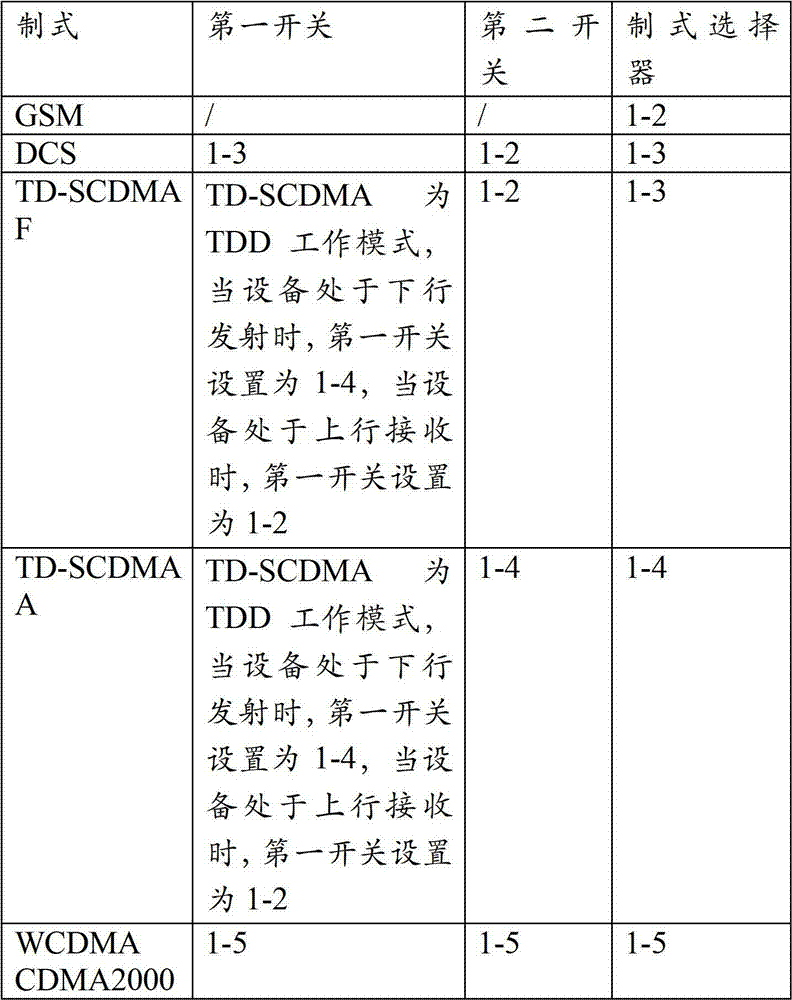
in this embodiment, the system selector 42, the first switch 43, and the second switch 44 are all controlled by software programs, and the connection relationship and the supported system of the contacts in each switch are shown in table 2.
TABLE 2
In the multi-system amplification module provided by this embodiment, different systems of circuits share the same uplink filter or downlink filter, receiver, and transmitter according to the characteristic that different systems have the same operating frequency band or are close to the operating frequency band.
EXAMPLE five
The present embodiment provides an antenna radiation device, including: the PCB antenna may be connected to the transceiver device provided in the first embodiment, the second embodiment and the third embodiment, and configured to receive an uplink radio frequency signal sent by a terminal and send the uplink radio frequency signal to the transceiver device, and receive a downlink radio frequency signal from the transceiver device and send the downlink radio frequency signal to the terminal.
EXAMPLE six
The present embodiment provides an indoor covering system, as shown in fig. 5, the system includes: antenna radiation means, transceiver means, and base station processing means; the transceiver device is respectively connected with the antenna radiation device and the base station processing device;
the antenna radiation device is used for receiving an uplink radio frequency signal of any one of a plurality of preset standards sent by a terminal in an uplink and sending the uplink radio frequency signal to the transceiver device; in downlink, receiving downlink radio frequency signals from the transceiver device and transmitting the downlink radio frequency signals to a terminal;
a transceiver device, configured to receive an uplink radio frequency signal from the antenna radiation device in an uplink, convert the uplink radio frequency signal into an uplink baseband signal of a corresponding system, and send the uplink baseband signal to the base station processing device; in a downlink, receiving a downlink baseband signal of any one of the predetermined multiple formats from the base station processing device, converting the downlink baseband signal into a downlink radio frequency signal of a corresponding format, and sending the downlink radio frequency signal to the antenna radiation device;
base station processing means for receiving uplink baseband signals from said transceiver means in an uplink; in the downlink, generating a downlink baseband signal of any one of the predetermined multiple systems, and sending the generated downlink baseband signal to the transceiver device.
For a specific operation principle of the indoor coverage system, reference is made to the transceiver device provided in the second embodiment and the antenna radiation device provided in the fifth embodiment, which are not described herein again.
The indoor coverage system provided by the embodiment is composed of a transceiver device, an antenna radiation device and a base station processing device, is suitable for indoor or outdoor small-range coverage, can be compatible with various systems, also supports two modes of a network interface and an optical fiber interface to return baseband signals, and has the advantages of simple network deployment and wide applicability.
EXAMPLE seven
The present embodiment provides another indoor covering system, as shown in fig. 6, the system including: a transceiver device, an antenna radiation device; wherein the transceiver device is connected with the antenna radiation device;
the antenna radiation device is used for receiving an uplink radio frequency signal of any one of a plurality of preset standards sent by a terminal in an uplink and sending the uplink radio frequency signal to the transceiver device; in downlink, receiving downlink radio frequency signals from the transceiver device and transmitting the downlink radio frequency signals to a terminal;
the transceiver device is used for receiving and processing the uplink radio frequency signal from the antenna radiation device in an uplink; and in a downlink, sending a downlink radio frequency signal to the antenna radiation device.
For a specific operation principle of the indoor coverage system, reference is made to the transceiver device provided in the third embodiment and the antenna radiation device provided in the fifth embodiment, which are not described herein again.
The indoor coverage system provided by the embodiment is composed of a transceiver device and an antenna radiation device, is suitable for indoor or outdoor small-range coverage, can omit the application of a base station processing device on the basis that the transceiver device has the function of processing baseband signals, simplifies a network structure, and has the advantages of compatibility with various systems, simple network deployment and wide applicability.
Example eight
The present embodiment provides an array antenna apparatus, as shown in fig. 7(1), the apparatus includes at least two antenna radiation devices 71, at least one middle transceiver device 72, at least one front transceiver device 73, and a connection backplane 74; the at least two antenna radiation devices 71 are in one-to-one correspondence with the at least one intermediate transceiver device 72 and the at least one head transceiver device 73;
each antenna radiation device 71 is connected with a corresponding intermediate transceiver device 72 or head transceiver device 73, and is configured to receive an uplink radio frequency signal of any one of multiple predetermined systems sent by a terminal in an uplink, and send the uplink radio frequency signal to the corresponding intermediate transceiver device 72 or head transceiver device 73; in the downlink, receiving downlink radio frequency signals from the corresponding intermediate transceiver device 72 or head transceiver device 73 and transmitting to the terminal;
as shown in fig. 7(2), each intermediate transceiver device 72 includes: a first multi-system processing unit 721 and a first backplane interface 722; wherein,
a first multi-system processing unit 721, configured to receive, in an uplink, an uplink radio frequency signal in any one of the multiple predetermined systems sent by the antenna radiation device 71 corresponding to the middle transceiver device 72, convert the uplink radio frequency signal into an uplink baseband signal in a corresponding system, and send the uplink baseband signal to the first backplane interface 722; in the downlink, a downlink baseband signal of any one of the predetermined multiple formats is received from the first backplane interface 722, and the downlink baseband signal is converted into a downlink radio frequency signal of a corresponding format and then sent to the antenna radiation device 71 corresponding to the intermediate transceiver device 72;
a first backplane interface 722, configured to receive, in an uplink, an uplink baseband signal from the first multi-system processing unit 721, and transmit the uplink baseband signal to the head transceiver apparatus 73 through the connection backplane 74; in a downlink, the connection back plate 74 receives a downlink baseband signal sent by the head transceiver device 73, and sends the downlink baseband signal to the first multi-system processing unit 721;
as shown in fig. 7(3), each head transceiver device 73 includes: a second multi-mode processing unit 731 and a second backplane interface 732; wherein,
a second multi-system processing unit 731, configured to receive, in an uplink, an uplink radio frequency signal in any one of the multiple predetermined systems sent by the antenna radiation device 71 corresponding to the head transceiver device 72, convert the uplink radio frequency signal into an uplink baseband signal in a corresponding system, and send the converted uplink baseband signal and the uplink baseband signal received from the second backplane interface 732; in the downlink, the received downlink baseband signal of any system in the predetermined multiple systems is sent to the second backplane interface 732 and converted into a downlink radio frequency signal of a corresponding system, and then sent to the antenna radiation device 71 corresponding to the first transceiver device 73;
a second backplane interface 732, configured to receive, in an uplink, an uplink baseband signal sent by the intermediate transceiver device 72 through the connection backplane 74, and send the uplink baseband signal to the second multi-system processing unit 731; in the downlink, a downlink baseband signal is received from the second multi-system processing unit 731, and is sent to the intermediate transceiver device 72 through the connection backplane 74.
Specifically, the predetermined multiple systems may be set according to actual needs, and may include: GSM, WCDMA, CDMA, TD-SCDMAA, DCS, TD-SCDMA F and other systems.
In this embodiment, each intermediate transceiver device 72 and each head transceiver device 73 are connected to a corresponding antenna radiation device 71 for use; the intermediate transceiver unit 72 is connected to the connection backplane 74 via the first backplane interface 722; the head transceiver unit 73 is connected to the connection backplane 74 via a second backplane interface 732; in the uplink, the intermediate transceiver device 72 sends the uplink baseband signal processed by the first multi-system processing unit 721 to the head transceiver device 73 sequentially through the first backplane interface 722 and the connection backplane 74; in the downlink, the head transceiver device 73 sequentially transmits the downlink baseband signal received by the second multi-system processing unit 731 to the intermediate transceiver device 72 through the second backplane interface 732 and the connection backplane 74.
In this embodiment, the head transceiver device 73 is the same as the intermediate transceiver device 72 in that: uplink radio frequency signals of any system in a plurality of predetermined systems can be received from the corresponding antenna radiation devices 71, and downlink radio frequency signals of any system in the plurality of predetermined systems can be sent out through the corresponding antenna radiation devices 71;
in this embodiment, the head transceiver device 73 differs from the intermediate transceiver device 72 in that: the head transceiver unit 73 collects the uplink baseband signals of the intermediate transceiver units 72 in the uplink and transmits the downlink baseband signals to the respective intermediate transceiver units 72 in the downlink. Specifically, the second multi-system processing unit 731 in the head transceiver device 73 has the following functions: in the uplink, converting the uplink radio frequency signal received from the antenna radiation device 71 corresponding to the head transceiver device 73 into an uplink baseband signal, and receiving the uplink baseband signal sent by the middle transceiver device 72 through the second backplane interface 732; in the downlink, the received downlink baseband signal is converted into a downlink rf signal and then sent to the antenna radiation device 71 corresponding to the first transceiver device 73, and sent to the intermediate transceiver device 72 through the second backplane interface 732.
The array antenna device provided by the embodiment can support the processing of signals of multiple systems, and when a part of the intermediate transceiver devices 72 or the head transceiver devices 73 have a fault, the other intermediate transceiver devices 72 or the head transceiver devices 73 still can work normally, so that the whole array antenna device is not influenced too much, and the reliability of the network is improved.
Preferably, each of the intermediate transceiver devices 72 corresponds to one of the at least one head transceiver device 73; then
The first backplane interface 722 is specifically configured to receive an uplink baseband signal from the first multi-system processing unit 721 in an uplink, and transmit the uplink baseband signal to the head transceiver device 73 corresponding to the intermediate transceiver device 72 through the connection backplane 74; in downlink, the connection backplane 74 receives a downlink baseband signal sent by the head transceiver device 73 corresponding to the middle transceiver device 72, and sends the downlink baseband signal to the first multi-system processing unit 721;
the second backplane interface 732 is specifically configured to receive, in an uplink, an uplink baseband signal sent by the intermediate transceiver device 72 corresponding to the head transceiver device 73 through the connection backplane 74, and send the uplink baseband signal to the second multi-system processing unit 731; in the downlink, a downlink baseband signal is received from the second multi-system processing unit 731, and is sent to the middle transceiver device 72 corresponding to the first transceiver device 73 through the connection backplane 74.
Specifically, the number of the intermediate transceiver devices 72 and the head transceiver devices 73 in the array antenna device may be multiple, and in order to ensure that the baseband signal transmission among the intermediate transceiver devices 72 and the head transceiver devices 73 can be performed in order, it is necessary to set the corresponding relationship between the intermediate transceiver devices 72 and the head transceiver devices 73, that is, each intermediate transceiver device 72 corresponds to only one head transceiver device 73, and one head transceiver device 73 may correspond to multiple intermediate transceiver devices 72 (hereinafter, the head transceiver device 73 governs multiple intermediate transceiver devices 72); each head transceiver unit 73 collects the uplink baseband signals of its own plurality of intermediate transceiver units 72 in the uplink and distributes the downlink baseband signals to its own plurality of intermediate transceiver units 72 in the downlink.
In a specific implementation, in the first transceiver device 73, the second multi-system processing unit 731 both converts the uplink radio frequency signal received from the antenna radiation device 71 of the first transceiver device 73 into an uplink baseband signal (hereinafter referred to as an uplink baseband signal generated by the second multi-system processing unit 731), and receives the uplink baseband signal (hereinafter referred to as an uplink baseband signal generated by the first multi-system processing unit 721) sent by each intermediate transceiver device 72 governed by the first transceiver device 73 from the second backplane interface 732; in order for the second multi-system processing unit 731 to be able to distinguish between the uplink baseband signal generated by itself and the uplink baseband signal generated by the first multi-system processing unit 721, the following manner may be adopted: when the first multi-system processing unit 721 of each intermediate transceiver device 72 is enabled to generate an uplink baseband signal, a first device identifier (the first device identifier corresponds to the intermediate transceiver device 72 one to one) is added to the uplink baseband signal to indicate which intermediate transceiver device 72 the uplink baseband signal is generated by; similarly, when the second multi-system processing unit 731 of each head transceiver device 73 is caused to generate an uplink baseband signal, a second device identifier (the second device identifier corresponds to the head transceiver device 73 one-to-one) is added to the uplink baseband signal to indicate which head transceiver device 73 the uplink baseband signal is generated by. In this way, the second multi-system processing unit 731 can determine whether the uplink baseband signal is generated by itself or the first multi-system processing unit 721 of the intermediate transceiver device 72 through the first device identifier or the second device identifier in the uplink baseband signal.
Similarly, in the first transceiver device 73, among the downlink baseband signals received by the second multi-system processing unit 731, there are downlink baseband signals that need to be converted into downlink radio frequency signals by itself (hereinafter, referred to as downlink baseband signals that need to be converted by the second multi-system processing unit 731 by itself), and downlink baseband signals that need to be sent to each managed intermediate transceiver device 72 through the second backplane interface 732 and converted into downlink radio frequency signals by each intermediate transceiver device 72 (hereinafter, referred to as downlink baseband signals that need to be converted by the first multi-system processing unit 721); in order for the second multi-system processing unit 731 to be able to distinguish between the downlink baseband signal to be converted by itself and the downlink baseband signal to be converted by the first multi-system processing unit 721, the following manner may be adopted: each downlink baseband signal includes a first device identifier or a second device identifier, and since the first device identifier has a one-to-one correspondence relationship with the intermediate transceiver device 72 and the second device identifier also has a one-to-one correspondence relationship with the first transceiver device 73, the second multi-system processing unit 731 can determine which transceiver device should perform conversion processing on the downlink baseband signal through the device identifiers; subsequently, the second multi-system processing unit 731 can convert the downlink baseband signal to be converted by itself into a downlink rf signal, and transmit the downlink baseband signal to be converted by the managed intermediate transceiver device 72 to the corresponding intermediate transceiver device 72. In addition, the second multi-system processing unit 731 may also send all the received downlink baseband signals to each intermediate transceiver device 72, and then each intermediate transceiver device 72 determines the downlink baseband signal to be processed by itself by determining whether the first device identifier included in the downlink baseband signal corresponds to itself,
preferably, as shown in fig. 7(4), the head transceiver device 73 further includes: a baseband processing unit 733, configured to receive and process an uplink baseband signal from the second multi-system processing unit 731 in an uplink; in the downlink, a downlink baseband signal of any system of the predetermined multiple systems is generated, and the generated downlink baseband signal is sent to the second multi-system processing unit 731.
Specifically, when the head transceiver device 73 includes the baseband processing unit 733, the head transceiver device 73 has a baseband processing function, and can perform processing functions in the physical layer, the communication interface protocol, and other layers on baseband signals of different systems without being connected to an external base station processing device.
In specific implementation, a network interface may be used to transmit baseband signals between the baseband processing unit 733 and the second multi-system processing unit 731 based on an IP protocol, and compared with a technology that only supports optical fiber to transmit baseband signals, the network interface based on the IP protocol can effectively utilize a network transmission mode with low cost and convenient maintenance, and avoid the problems of high cost of optical fiber resources, inconvenient maintenance and the like caused by only supporting optical fiber transmission.
Preferably, the baseband processing unit 733 is further configured to: the beam downtilt factor is determined and sent to the second multi-system processing unit 731.
Specifically, the baseband processing unit 733 may issue a beam downtilt factor to the second multi-system processing unit 731, and after receiving the beam downtilt factor, the second multi-system processing unit 731 may further send the beam downtilt factor to the first multi-system processing unit 721 through the second backplane interface 732, the connection backplane 74, and the first backplane interface 722 in sequence; then, the second multi-system processing unit 731 and the first multi-system processing unit 721 perform corresponding processing with reference to the beam down-tilt factor in the process of generating the uplink baseband signal or the downlink radio frequency signal, thereby implementing the function of carrier beam down-tilt. Specifically, the beam downtilt factor directly affects DDC and DUC processing employed by the second multi-system processing unit 731 and the first multi-system processing unit 721, and thus beam downtilt in both horizontal and vertical directions can be achieved. The method determines the beam downtilt factor by an algorithm mode, and further influences the DDC and DUC processing adopted by the second multi-system processing unit 731 and the first multi-system processing unit 721; compared with the mechanical downtilt technology, the method can generate the beam downtilt factor at any time according to the requirement without adjusting the downtilt angle, flexibly realize the beam downtilt function, and has convenient and quick realization process and smaller workload; compared with the electrically-adjusted downtilt technology, the method does not need to be provided with a shifter, not only saves the occupied space of equipment and the investment cost, but also can realize the beam downtilt function in the vertical direction and the horizontal direction.
Preferably, the determining, by the baseband processing unit 733, a beam downtilt factor includes:
determining a beam downtilt factor corresponding to a set system; and/or;
a beam downtilt factor corresponding to the set carrier is determined.
Specifically, the baseband processing unit 733 may determine a beam downtilt factor for a set system to implement a function of individually adjusting a carrier beam downtilt of a certain system, and may implement a function of simultaneously adjusting carrier beams of multiple systems when corresponding beam downtilt factors are determined for different systems, respectively. In a specific implementation, when the baseband processing unit 733 generates the beam downtilt factor, the beam downtilt factor includes a format identifier (the format identifier corresponds to a plurality of formats in the present invention one to one), so as to indicate a set format corresponding to the beam downtilt factor; the second multi-mode processing unit 731 receives the beam downtilt factor corresponding to the set mode, and sends the beam downtilt factor to the first multi-mode processing unit 721; then, the second multi-system processing unit 731 and the first multi-system processing unit 721 determine that a beam down tilt function needs to be performed for a set system corresponding to the system identifier according to the system identifier in the beam down tilt factor, and perform corresponding processing (such as DDC and DUC processing) with reference to the beam down tilt factor when generating an uplink baseband signal or a downlink radio frequency signal of the set system, thereby implementing a carrier beam down tilt function.
Specifically, the baseband processing unit 733 may also determine a beam downtilt factor for a set carrier to implement a function of individually adjusting a beam downtilt of a certain carrier, and when determining a corresponding beam downtilt factor for different carriers, may implement a function of simultaneously adjusting a plurality of carrier beams downtilt. In a specific implementation, when the baseband processing unit 733 generates the beam downtilt factor, the beam downtilt factor includes a carrier identifier to indicate a set carrier corresponding to the beam downtilt factor; the second multi-mode processing unit 731 receives the beam downtilt factor corresponding to the set carrier, and sends the beam downtilt factor to the first multi-mode processing unit 721; then, the second multi-system processing unit 731 and the first multi-system processing unit 721 determine that the beam down tilt function needs to be performed for the set carrier corresponding to the carrier identifier according to the carrier identifier included in the beam down tilt factor, and perform corresponding processing (such as DDC and DUC processing) with reference to the beam down tilt factor when generating the uplink baseband signal or the downlink radio frequency signal of the set carrier, thereby implementing the function of carrier beam down tilt.
Preferably, the determining, by the baseband processing unit 733, a beam downtilt factor corresponding to a set carrier includes: and determining a beam downtilt factor corresponding to the set uplink carrier and/or the set downlink carrier.
Specifically, the carrier identifier included in the generated beam downtilt factor by the baseband processing unit 733 may indicate not only the corresponding set carrier but also the corresponding uplink carrier or downlink carrier; the second multi-system processing unit 731 and the first multi-system processing unit 721 determine, according to the carrier identifier included in the beam downtilt factor, that a beam downtilt function needs to be performed with respect to a set uplink carrier or a set downlink carrier corresponding to the carrier identifier, for example, when it is determined that the carrier identifier included in the beam downtilt factor corresponds to a certain uplink carrier, when an uplink baseband signal is generated, DDC processing is performed with reference to the beam downtilt factor, thereby implementing a beam downtilt function for setting an uplink carrier; or, when it is determined that a carrier identifier included in the beam downtilt factor corresponds to a certain downlink carrier, the DUC processing is performed with reference to the beam downtilt factor when a downlink radio frequency signal is generated, so as to implement a function of setting a beam downtilt of the downlink carrier.
As shown in fig. 7(5), the array antenna apparatus provided in this embodiment can implement a down tilt function for any carrier beam in the horizontal direction and the vertical direction;
as shown in fig. 7(6), the array antenna apparatus provided in this embodiment may further implement a down tilt function for multiple carrier beams in the horizontal direction and the vertical direction at the same time;
as shown in fig. 7(7), the array antenna apparatus provided in this embodiment may further implement a down tilt function for the uplink carrier beam and the downlink carrier beam in the horizontal direction and the vertical direction at the same time.
Preferably, as shown in fig. 7(8), the head transceiver device 73 further includes: an external interface 734, configured to receive an uplink baseband signal from the second multi-system processing unit 731 in an uplink, and send the uplink baseband signal to a base station processing apparatus; in the downlink, a downlink baseband signal of any system of the predetermined multiple systems is received from the base station processing apparatus and sent to the second multi-system processing unit 731.
Specifically, when the first transceiver device 73 does not have a baseband processing function, it can be connected to an external base station processing device having a baseband processing function by using an external interface, so as to achieve the purpose of sending an uplink baseband signal to the base station processing device for corresponding processing and receiving a downlink baseband signal from the base station processing device; the external interface can be an optical fiber interface and supports the function of transmitting baseband signals by adopting an optical fiber network.
Preferably, the external interface 734 is further configured to: receive the beam downtilt factor sent by the base station processing apparatus, and send the beam downtilt factor to the second multi-system processing unit 731.
Specifically, similar to the baseband processing unit 733 determining the beam downtilt factor and sending the beam downtilt factor to the second multi-system processing unit 731 to implement the beam downtilt function, the base station processing apparatus may also determine the beam downtilt factor and send the beam downtilt factor to the second multi-system processing unit 731 to implement the beam downtilt function, and the specific implementation process is referred to above and is not described herein again.
Preferably, the second multi-system processing unit 731 is further configured to: receiving the beam down-tilt factor, and generating an uplink baseband signal and/or a downlink radio frequency signal according to the beam down-tilt factor, and/or sending the beam down-tilt factor to the first multi-mode processing unit 721;
the first multi-system processing unit 721 is further configured to: and receiving the beam downtilt factor, and generating an uplink baseband signal and/or a downlink radio frequency signal according to the beam downtilt factor.
Specifically, after receiving the beam down-tilt factor, the second multi-system processing unit 731, on one hand, performs corresponding processing with reference to the beam down-tilt factor when generating an uplink baseband signal or a downlink radio frequency signal to implement a corresponding beam down-tilt function, and on the other hand, sends the beam down-tilt factor to the first multi-system processing unit 721 through the second backplane interface 732, the connection backplane 74, and the first backplane interface 722 in sequence; after receiving the beam down-tilt factor, the first multi-system processing unit 721 also performs corresponding processing with reference to the beam down-tilt factor when generating the uplink baseband signal or the downlink radio frequency signal, so as to implement a corresponding beam down-tilt function; for the detailed process, reference is made to the foregoing description, and details are not repeated herein.
Preferably, as shown in fig. 7(9), the first multi-system processing unit 721 specifically includes: a first multi-standard amplification module 7211, a first multi-standard radio frequency processing module 7212, and a first protocol data processing module 7213; wherein,
a first multi-system amplifying module 7211, configured to receive, in an uplink, an uplink radio frequency signal in any one of the multiple predetermined systems sent by the antenna radiation device 71 corresponding to the intermediate transceiver device 72, and send the uplink radio frequency signal to the first multi-system radio frequency processing module 7212; in the downlink, a downlink radio frequency signal is received from the first multi-standard radio frequency processing module 7212, and the downlink radio frequency signal is sent to the antenna radiation device 71 corresponding to the intermediate transceiver device 72;
a first multi-standard radio frequency processing module 7212, configured to demodulate, in an uplink, the uplink radio frequency signal received from the first multi-standard amplification module 7211 into an uplink digital signal of a corresponding standard, and send the uplink digital signal to the first protocol data processing module 7213; in a downlink, the downlink digital signal received from the first protocol data processing module 7213 is modulated into a downlink radio frequency signal of a corresponding system, and the downlink radio frequency signal is sent to the first multi-system amplifying module 7211;
a first protocol data processing module 7213, configured to convert, in an uplink, an uplink digital signal received from the first multi-system radio frequency processing module 7212 into an uplink baseband signal of a corresponding system, and send the uplink baseband signal to the first backplane interface 722; in the downlink, the downlink baseband signal of any one of the predetermined multiple formats received from the first backplane interface 722 is converted into a downlink digital signal of a corresponding format, and then the downlink digital signal is sent to the first multi-format radio frequency processing module 7212.
Specifically, the first multi-system amplification module 7211 has functions of identifying radio frequency signals of different system types, and performing corresponding filtering processing on the radio frequency signals of different system types;
the first multi-system radio frequency processing module 7212 is configured to perform a function of mutual conversion between a radio frequency signal and a digital signal, specifically, convert an uplink radio frequency signal into an uplink digital signal by using analog-to-digital conversion, and convert a downlink digital signal into a downlink radio frequency signal by using digital-to-analog conversion;
the first protocol data processing module 7213 is configured to complete conversion processing of a digital signal and a baseband signal, and specifically, perform DDC, uplink digital filtering, framing and other processing on an uplink digital signal to obtain an uplink baseband signal, and perform frame decoding, downlink digital filtering, DUC, digital peak clipping and other processing on a downlink baseband signal to obtain a downlink digital signal;
it should be noted that, because the radio frequency signals, the digital signals, and the baseband signals corresponding to different systems are different, when the first multi-system amplification module 7211, the first multi-system radio frequency processing module 7212, and the first protocol data processing module 7213 process the radio frequency signals, the digital signals, and the baseband signals of different systems, different specific processing modes should also be adopted, for example: the first multi-system amplification module 7211 has different filter stages, filter suppression, and the like configured for different systems; the first multi-system radio frequency processing module 7212 has different radio frequency filters for local oscillators configured in different systems; the first protocol data processing module 7213 has different DUC, DDC, digital peak clipping functions (including coefficients for peak clipping and the number of steps for peak clipping) configured for different systems, and the like.
Preferably, as shown in fig. 7(10), the first multi-system amplification module 7211 specifically includes: a first antenna interface 72111, a first format selector 72112, and a plurality of first format circuits 72113; the plurality of first standard circuits 72113 correspond to the predetermined plurality of standards one to one; wherein,
a first format selector 72112, configured to receive, in an uplink, an uplink radio frequency signal sent by the antenna radiation device 71 corresponding to the intermediate transceiver device 72 through the first antenna interface 72111, and send the uplink radio frequency signal to a first format circuit 72113 corresponding to a format of the uplink radio frequency signal; in downlink, the downlink radio frequency signal received from any of the first standard circuits 72113 is sent to the antenna radiation device 71 corresponding to the intermediate transceiver device 72 through the first antenna interface 72111;
each first standard circuit 72113 is configured to send, in an uplink, an uplink radio frequency signal received from the first standard selector 72112 to the first multi-standard radio frequency processing module 7212; in the downlink, the downlink rf signal received from the first multi-standard rf processing module 7212 is sent to the first standard selector 72112.
Specifically, in order to support processing of signals of multiple systems, the first multi-system amplification module 7211 needs to include multiple first-system circuits 72113, each first-system circuit 72113 is dedicated to processing signals of one system, for example, when the multiple predetermined systems are GSM, WCDMA, and CDMA, respectively, the first multi-system amplification module 7211 needs to include three first-system circuits 72113 for processing GSM signals, WCDMA signals, and CDMA signals, respectively; in addition, the first multi-standard amplification module 7211 uses the first standard selector 72112 to send the signal to the corresponding first standard circuit 72113 for processing according to the standard type of the signal, and in a specific implementation, the first standard selector 72112 is controlled by a software program, can automatically determine the standard type of the signal, and accurately send the signal to the corresponding first standard circuit 72113 for processing.
In addition, the first format selector 72112 may be set by a software program to process only a signal of a certain set format within a certain period of time, and when receiving the signal of the set format, the first format selector 72112 sends the signal to the corresponding first format circuit 72113 for processing, and when receiving signals of other formats, the first format selector 72112 does not process the signal. That is to say, the intermediate transceiver device 72 provided in this embodiment can, in addition to simultaneously supporting multi-system signal processing, enable the intermediate transceiver device 72 to process only single-system signals within a period of time through this setting; therefore, in the array antenna apparatus, each intermediate transceiver device 72 can be set to support only single-system signal processing, and different settings can be performed according to actual situations, for example, one intermediate transceiver device 72 is set to support only CDMA-system processing for a period of time, and the intermediate transceiver device 72 is set to support only GSM-system processing for another period of time, or some intermediate transceiver devices 72 are set to support CDMA-system processing for a period of time, and other intermediate transceiver devices 72 are set to support GSM-system processing for a period of time, so that the array antenna apparatus can have flexible and variable system coverage functions through different setting modes.
Preferably, as shown in fig. 7(11), the first standard circuit 72113 specifically includes: a first up filter C1, a first down filter C2, a first receiver C3, and a first transmitter C4; wherein,
a first uplink filter C1, configured to filter, in an uplink, an uplink radio frequency signal received from the first format selector 72112, and send the filtered uplink radio frequency signal to the first receiver C3;
a first downlink filter C2, configured to filter, in a downlink, a downlink radio frequency signal received from the first transmitter C4 and send the filtered downlink radio frequency signal to the first format selector 72112;
a first receiver C3, configured to send, in an uplink, an uplink radio frequency signal received from the first uplink filter C1 to the first multi-standard radio frequency processing module 7212;
a first transmitter C4, configured to send, in a downlink, the downlink radio frequency signal received from the first multi-standard radio frequency processing module 7212 to the first downlink filter C2.
Specifically, since different standards have different uplink working frequency bands and downlink working frequency bands, in order to implement the function of the first standard circuit 72113 in processing radio frequency signals of corresponding standards, a special first uplink filter C1 should be designed for the uplink working frequency bands of the standards, and a special first downlink filter C2 should be designed for the downlink working frequency bands of the standards, so as to achieve the purpose of processing the radio frequency signals of the standards;
in specific implementation, when an uplink working frequency band and a downlink working frequency band of a certain system are consistent (for example, in TD-SCDMA system), the same filter can be used to realize the functions of uplink filtering and downlink filtering;
in addition, when the uplink working frequency bands and the downlink working frequency bands of different systems are respectively consistent (such as a WCDMA system and a CDMA2000 system) or close (such as a DCS system and a TD-SCDMA system), a corresponding first uplink filter C1 can be designed for the uplink working frequency band, a corresponding first downlink filter C2 can be designed for the downlink working frequency band, and circuits corresponding to the different systems share one set of a first uplink filter C1 and a first downlink filter C2, so that the same filters are used in the same working frequency band, thereby simplifying equipment and saving resources;
specifically, the radio frequency signals transmitted and received in the circuits 72113 of different first standards can also share one set of the first receiver C3 and the first transmitter C4 according to actual situations, so as to further achieve the purposes of simplifying the device structure and saving resources.
Preferably, as shown in fig. 7(12), the second multi-system processing unit 731 specifically includes: a second multi-system amplifying module 7311, a second multi-system radio frequency processing module 7312, and a second protocol data processing module 7313; wherein,
a second multi-system amplifying module 7311, configured to receive, in an uplink, an uplink radio frequency signal in any one of the multiple predetermined systems sent by the antenna radiation device 71 corresponding to the head transceiver device 73, and send the uplink radio frequency signal to the second multi-system radio frequency processing module 7312; in downlink, receive a downlink radio frequency signal from the second multi-system radio frequency processing module 7312, and send the downlink radio frequency signal to the antenna radiation device 71 corresponding to the head transceiver device 73;
a second multi-system radio frequency processing module 7312, configured to demodulate, in an uplink, the uplink radio frequency signal received from the second multi-system amplifying module 7311 into an uplink digital signal of a corresponding system, and send the uplink digital signal to the second protocol data processing module 7313; in downlink, the downlink digital signal received from the second protocol data processing module 7313 is modulated into a downlink radio frequency signal of a corresponding system, and the downlink radio frequency signal is sent to the second multi-system amplifying module 7311;
a second protocol data processing module 7313, configured to convert, in an uplink, an uplink digital signal received from the second multi-system radio frequency processing module 7312 into an uplink baseband signal of a corresponding system, and send the uplink baseband signal and the uplink baseband signal received from the second backplane interface 732; in the downlink, the received downlink baseband signal of any system in the predetermined multiple systems is sent to the second backplane interface 732 and converted into a downlink digital signal of a corresponding system, and then sent to the second multi-system radio frequency processing module 7312.
Specifically, the specific implementation functions of the modules in the second multi-standard processing unit 731 are similar to the specific implementation functions of the modules in the first multi-standard processing unit 721, and are not described herein again.
Preferably, as shown in fig. 7(13), the second multi-system amplifying module 7311 specifically includes: a second antenna interface 73111, a second format selector 73112, and a plurality of second format circuits 73113; the second standard circuits 73113 correspond to the predetermined standards one by one; wherein,
a second format selector 73112, configured to receive, in an uplink, the uplink radio frequency signal sent by the antenna radiation device 71 corresponding to the head transceiver device 73 through the second antenna interface 73111, and send the uplink radio frequency signal to a second format circuit 73113 corresponding to the format of the uplink radio frequency signal; in downlink, the downlink radio frequency signal received from any of the second standard circuits 73113 is sent to the antenna radiation device 71 corresponding to the head transceiver device 73 through the second antenna interface 73111;
each second-standard circuit 73113 is configured to send, in an uplink, an uplink radio frequency signal received from the second-standard selector 73112 to the second multi-standard radio frequency processing module 7312; in downlink, the downlink rf signal received from the second multi-standard rf processing module 7312 is sent to the second-standard selector 73112.
Specifically, the specific implementation functions of each functional device in the second multi-system amplification module 7311 are similar to the specific implementation functions of each functional device in the first multi-system amplification module 7211, and are not described herein again.
Preferably, as shown in fig. 7(14), the second standard circuit 73113 specifically includes: a second up filter D1, a second down filter D2, a second receiver D3, and a second transmitter D4; wherein,
a second uplink filter D1, configured to, in an uplink, filter an uplink radio frequency signal received from the second format selector 73112 and send the filtered uplink radio frequency signal to the second receiver D3;
a second downlink filter D2, configured to filter, in a downlink, a downlink radio frequency signal received from the second transmitter D4 and send the filtered downlink radio frequency signal to the second format selector 73112;
a second receiver D3, configured to send, in an uplink, the uplink radio frequency signal received from the second uplink filter D1 to the second multi-system radio frequency processing module 7312;
a second transmitter D4, configured to send, in a downlink, the downlink radio frequency signal received from the second multi-system radio frequency processing module 7312 to the second downlink filter D2.
Specifically, the specific implementation functions of each functional device in the second standard circuit 73113 are similar to the specific implementation functions of each functional device in the first standard circuit 72113, and are not described herein again.
Preferably, as shown in fig. 7(15), the second protocol data processing module 7313 specifically includes: a primary transceiver processor 73131, an intermediate transceiver processor 73132, and a master transceiver processor 73133; wherein,
a primary transceiver 73131, configured to convert, in an uplink, an uplink digital signal received from the second multi-standard radio frequency processing module 7312 into an uplink baseband signal of a corresponding standard, and send the uplink baseband signal to the primary transceiver 73133; in downlink, the downlink baseband signal received from the master transceiver 73133 is converted into a downlink digital signal of a corresponding system, and then the downlink digital signal is sent to the second multi-system rf processing module 7312;
an intermediate transceiver processor 73132 for transmitting the uplink baseband signal received from the second backplane interface 732 to the master transceiver processor 73133 in an uplink; in the downlink, sending downlink baseband signals received from the general transceiver processor 73133 to the second backplane interface 732;
a master transceiver 73133, configured to receive uplink baseband signals from the head transceiver 73131 and the intermediate transceiver 73132 in an uplink, and perform framing on the received uplink baseband signals before sending out; in the downlink, a downlink baseband signal of any system of the predetermined multiple systems is received, and the received downlink baseband signal is deframed and then sent to the head transceiver 73131 and the intermediate transceiver 73132, respectively.
Specifically, in the uplink, the second protocol data processing module 7313 not only converts the uplink digital signal sent by the second multi-system radio frequency processing module 7312 into an uplink baseband signal (hereinafter, referred to as an uplink baseband signal generated by the second protocol data processing module 7313 itself), but also receives the uplink baseband signal of each intermediate transceiver device 72 governed by the first transceiver device 73 (hereinafter, referred to as an uplink baseband signal generated by the first protocol data processing module 7213) through the second backplane interface 732; in the downlink, the second protocol data processing module 7313 not only needs to send the received downlink baseband signal to the second multi-system radio frequency processing module 7312 for processing (hereinafter, referred to as a downlink baseband signal to be processed by the second protocol data processing module 7313 itself for short), but also needs to send the received downlink baseband signal to each intermediate transceiver device 72 governed by the head transceiver device 73 through the second backplane interface 732 for processing (hereinafter, referred to as a downlink baseband signal to be processed by the first protocol data processing module 7213 for short);
in this embodiment, the second protocol data processing module 7313 is divided into the first transceiver 73131, the intermediate transceiver 73132 and the total transceiver 73133, so as to process the uplink baseband signal generated by itself and the uplink baseband signal generated by the first protocol data processing module 7213 separately in the uplink and process the downlink baseband signal to be processed by itself and the downlink baseband signal to be processed by the first protocol data processing module 7213 separately in the downlink.
Example nine
This embodiment provides a base station processing apparatus for providing a baseband processing function for an array antenna apparatus according to the eighth embodiment by a base station processing apparatus provided by this embodiment when a head transceiver apparatus 73 of the array antenna apparatus according to the eighth embodiment does not have the baseband processing function by itself, as shown in fig. 8, the base station processing apparatus includes:
a baseband signal processing module 81, configured to process, in an uplink, an uplink baseband signal of any system in the received predetermined multiple systems; in the downlink, generating a downlink baseband signal of any system in the preset multiple systems and sending the downlink baseband signal out;
and the beam downtilt module 82 is used for determining the beam downtilt factor and sending out the beam downtilt factor.
Specifically, after the base station processing apparatus provided in this embodiment is connected to the array antenna apparatus provided in the eighth embodiment, the baseband signal processing module 81 can receive, in an uplink, an uplink baseband signal of any system in the predetermined multiple systems sent by the head transceiver apparatus 73, and complete a processing function of performing layers such as a physical layer and a communication interface protocol on baseband signals of different systems, and in a downlink, generate a downlink baseband signal of any system in the predetermined multiple systems, and send the downlink baseband signal to the array antenna apparatus.
Specifically, the beam downtilt module 82 determines a beam downtilt factor through an algorithm and transmits the beam downtilt factor to the array antenna apparatus, so as to implement a beam downtilt function.
Preferably, the beam downtilt module 82 is specifically configured to:
determining a beam downtilt factor corresponding to a set system; and/or;
a beam downtilt factor corresponding to the set carrier is determined.
The determining, by the beam downtilt module 82, a beam downtilt factor corresponding to a set carrier specifically includes: and determining a beam downtilt factor corresponding to the set uplink carrier and/or the set downlink carrier.
Specifically, the specific process of determining the beam downtilt factor by the beam downtilt module 82 is similar to the process of determining the beam downtilt factor by the baseband processing unit 733 in the eighth embodiment, and is not described herein again.
Example ten
The present embodiment provides an array antenna apparatus, as shown in fig. 9, the array antenna apparatus including: the antenna radiation device comprises a first transceiver device with the serial number of 1, a middle transceiver device with the serial number of 2-N and an antenna radiation device with the serial number of 1-N, wherein the first transceiver device/the middle transceiver device with the same serial number are connected with the antenna radiation device, K is an integer and is more than or equal to 2; n is an integer, and N is more than or equal to K;
in this embodiment, the first transceiver device with serial number 1 governs the intermediate transceiver devices with serial numbers 2 to N, and as shown in fig. 9, the baseband signals (uplink/downlink baseband signals) and the beam down-tilt factor are transmitted between the first transceiver device with serial number 1 and each intermediate transceiver device through the connection backplane.
EXAMPLE eleven
The present embodiment provides a method for performing a beam down tilt function on a set carrier by an array antenna apparatus according to a beam down tilt factor, where the array antenna apparatus includes: the base station comprises an antenna radiation device, a first transceiver device, a first intermediate transceiver device, a second intermediate transceiver device and a connection back plate, wherein the first transceiver device (without a baseband processing function) is connected with an external base station processing device, the first transceiver device is set to be only capable of processing WCDMA system signals, the first intermediate transceiver device is set to be only capable of processing GSM system signals, and the second intermediate transceiver device is set to be only capable of processing CDMA system signals in the current time period.
In this embodiment, for the uplink traffic, as shown in fig. 10 (1):
the first transceiver device receives a beam down-tilt factor WU1 aiming at an uplink WCDMA carrier 1, a beam down-tilt factor WU2 aiming at an uplink WCDMA carrier 2, a beam down-tilt factor WU3 aiming at an uplink GSM carrier 1, a beam down-tilt factor WU4 aiming at an uplink CDMA carrier 1 and a beam down-tilt factor WU5 aiming at an uplink CDMA carrier 2, which are transmitted by the base station processing device;
the head transceiver device itself retains the beam down-tilt factors WU1 and WU2, sends the beam down-tilt factor WU3 to the first intermediate transceiver device, and sends the beam down-tilt factors WU4 and WU5 to the second intermediate transceiver device;
when the first transceiver device generates the uplink WCDMA carrier 1, the relevant operation of the beam down-tilting factor WU1 is added in the DDC processing so as to achieve the function of beam down-tilting the uplink WCDMA carrier 1; when the first transceiver device generates a WCDMA carrier 2, the relevant operation of a beam down-tilting factor WU2 is added in the DDC processing so as to achieve the function of beam down-tilting the uplink WCDMA carrier 2;
after receiving the beam down-tilt factor WU3, the first intermediate transceiver device adds the relevant operation of the beam down-tilt factor WU3 in the DDC processing to generate the uplink GSM carrier 1, so as to perform the beam down-tilt function on the uplink GSM carrier 1; the first intermediate transceiver device sends the generated uplink GSM carrier 1 to the first transceiver device through a connection backboard;
after receiving the beam down-tilt factors WU4 and WU5, the second intermediate transceiver device adds the correlation operation of the beam down-tilt factor WU4 in the DDC processing to generate the uplink CDMA carrier 1, so as to perform the beam down-tilt function on the uplink CDMA carrier 1; when the second intermediate transceiver device generates the uplink CDMA carrier 2, the correlation operation for the beam down-tilt factor WU5 is added to the DDC process to achieve the beam down-tilt function for the uplink CDMA carrier 2; the second intermediate transceiver device sends the generated uplink CDMA carrier 1 and the uplink CDMA carrier 2 to the first transceiver device through a connecting backboard;
the first transceiver device performs framing processing on the uplink WCDMA carrier 1 and the uplink WCDMA carrier 2 generated by the first transceiver device and the uplink GSM carrier 1, the uplink CDMA carrier 1 and the uplink CDMA carrier 2 received through the connecting backboard, and then sends the frames to the base station processing device for processing.
In this embodiment, for downlink traffic, as shown in fig. 10 (2):
the first transceiver device receives downlink WCDMA carrier 1, downlink WCDMA carrier 2, downlink GSM carrier 1, downlink CDMA carrier 1 and downlink CDMA carrier 2 sent by the base station processing device, and also receives beam downtilt factor WD1 for downlink WCDMA carrier 1, beam downtilt factor WD2 for downlink WCDMA carrier 2, beam downtilt factor WD3 for downlink GSM carrier 1, beam downtilt factor WD4 for downlink CDMA carrier 1, and beam downtilt factor WD5 for downlink CDMA carrier 2 sent by the base station processing device;
the first transceiver device performs de-framing processing on the received downlink carrier, and then reserves downlink WCDMA carrier 1 and downlink WCDMA carrier 2, and beam downtilt factors WD1 and WD 2; sending downlink GSM carrier 1 and beam downtilt factor WD3 to a first intermediate transceiver device, downlink CDMA carrier 1 and downlink CDMA carrier 2, and beam downtilt factors WD4 and WD5 to a second intermediate transceiver device;
when the first transceiver device processes the downlink WCDMA carrier 1 (the baseband signal is converted into a radio frequency signal of a corresponding system), the adopted DUC processing is added with the relevant operation of a beam down-tilt factor WD1 so as to achieve the function of beam down-tilt of the downlink WCDMA carrier 1; when the first transceiver device processes the downlink WCDMA carrier 2, the related operation of the beam down-tilting factor WD2 is added in the adopted DUC processing, so as to achieve the function of beam down-tilting the downlink WCDMA carrier 2; the first transceiver device sends out the generated downlink radio frequency signal through an antenna radiation device connected with the first transceiver device;
when the first intermediate transceiver device processes the downlink GSM carrier 1, the adopted DUC processing is added with the relevant operation of the beam downtilt factor WD3, so as to achieve the function of beam downtilt of the downlink GSM carrier 1; the first intermediate transceiver device sends out the generated downlink radio frequency signal through an antenna radiation device connected with the first intermediate transceiver device;
when the second intermediate transceiver device processes the downlink CDMA carrier 1, the DUC processing adopted adds the correlation operation of the beam downtilt factor WD4, so as to achieve the function of beam downtilt for the downlink CDMA carrier 1; when the second intermediate transceiver device processes the downlink CDMA carrier 2, the DUC processing adopted adds the correlation operation of the beam downtilt factor WD5, so as to achieve the function of beam downtilt for the downlink CDMA carrier 2; the second intermediate transceiver device sends out the generated downlink radio frequency signal through the antenna radiation device connected with the second intermediate transceiver device.
In this embodiment, the array antenna apparatus implements the beam downtilt function for carriers of different systems and the beam downtilt function for uplink and downlink carriers according to the beam downtilt factor, and compared with the mechanical downtilt technology and the electrical downtilt technology, the method satisfies the flexible beam forming requirement on one hand, greatly improves the capacity of the network coverage system, and does not need additional configuration equipment on the other hand, thereby saving space and capital investment and having higher practical value.
Example twelve
The present embodiment provides an array antenna apparatus, including: the antenna radiation device comprises intermediate transceiver devices with serial numbers of 1-14 respectively, first transceiver devices with serial numbers of 15 and 16 respectively, and antenna radiation devices corresponding to the intermediate transceiver devices and the first transceiver devices respectively, wherein the first transceiver device with the serial number of 15 governs the intermediate transceiver devices with the serial numbers of 1-7 respectively, and the first transceiver device with the serial number of 16 governs the intermediate transceiver devices with the serial numbers of 8-14 respectively;
as shown in fig. 11(1), in a first setting period, the middle transceiver devices with serial numbers 1 to 14 and the first transceiver devices with serial numbers 15 and 16 respectively are currently set to support only the GSM system;
as shown in fig. 11(2), in the second setting period, the intermediate transceiver devices with serial numbers 1-4 are currently set to only support the GSM system, the intermediate transceiver devices with serial numbers 5-10 are currently set to only support the WCDMA system, and the intermediate transceiver devices with serial numbers 11-14 and the first transceiver devices with serial numbers 15 and 16 respectively are currently set to only support the TD-scdma system.
In this embodiment, each first transceiver device and each intermediate transceiver device are respectively used for processing a specific system signal in different time periods according to different settings, and the method enhances the system coverage flexibility of the array antenna device.
EXAMPLE thirteen
The embodiment provides an outdoor covering system, which comprises an array antenna device and a base station processing device; wherein,
the array antenna device is used for converting the received uplink radio frequency signals of any system in a plurality of predetermined systems into uplink baseband signals of a corresponding system in an uplink and sending the uplink baseband signals to the base station processing device; in a downlink, receiving a downlink baseband signal of any system in the preset multiple systems from the base station processing device, converting the downlink baseband signal into a downlink radio frequency signal of a corresponding system, and sending the downlink radio frequency signal;
the base station processing device is used for receiving and processing uplink baseband signals of any system in the preset multiple systems from the array antenna device in an uplink; and in a downlink, generating a downlink baseband signal of any system in the preset multiple systems and sending the downlink baseband signal to the array antenna device.
For a specific operation principle of the outdoor coverage system, reference is made to the array antenna device provided in the eighth embodiment and the specific operation principle of the base station processing device provided in the ninth embodiment, which are not described herein again.
The outdoor coverage system provided by the embodiment is composed of the array antenna device and the base station processing device, is suitable for outdoor large-scale coverage, can be compatible with various systems, also supports two modes of a network interface and an optical fiber interface to return baseband signals, and has the advantages of simple network deployment and wide applicability.
Example fourteen
The embodiment provides an outdoor covering system, which comprises an array antenna device.
In this embodiment, the first transceiver device in the array antenna device includes a baseband processing unit, so that the baseband signal processing function can be completed without connecting with an external base station processing device. For specific operation principle of the outdoor coverage system, reference is made to specific operation principle of the transceiver device provided in the eighth embodiment, and details are not described herein again.
The outdoor coverage system provided by the embodiment is composed of the array antenna devices, is suitable for outdoor large-scale coverage, can omit the application of a base station processing device on the basis that the first transceiver device has the function of processing baseband signals, simplifies the network structure, and has the advantages of compatibility with various systems, simple network deployment and wide applicability.
Example fifteen
As shown in fig. 12, the conventional configuration of one WCDMA and GSM 3 sector requires 6 RRHs and 6 antennas, and a total of 12 radio frequency feeders are required according to the typical configuration of two feeders for transceiving by each RRH;
this embodiment provides an outdoor covering system, as shown in fig. 13, which employs an array antenna device, and as can be seen from fig. 13, only 3 pairs of optical fibers are directly connected to the array antenna device.
Example sixteen
In the present embodiment, as shown in fig. 14, in the array antenna apparatus adopted by the outdoor coverage system provided in the present embodiment, the first transceiver apparatus includes a baseband processing unit, so that the overall coverage system is further simplified for the erection of WCDMA and GSM base stations.
The outdoor coverage system provided by the embodiment has high flexibility, can utilize the existing sky resources to the maximum extent, and provides a good solution for improving the coverage and expanding the capacity for equipment manufacturers.
It will be apparent to those skilled in the art that various changes and modifications may be made without departing from the spirit and scope of the invention. Thus, if such modifications and variations of the present invention fall within the scope of the claims and their equivalents, the present invention is also intended to include such modifications and variations.
Claims (29)
1. A transceiver apparatus, comprising: the multi-system processing unit is used for receiving an uplink radio frequency signal of any one of a plurality of predetermined systems in an uplink, converting the uplink radio frequency signal into an uplink baseband signal of a corresponding system and sending the uplink baseband signal; in the downlink, receiving a downlink baseband signal of any one of the predetermined multiple systems, converting the downlink baseband signal into a downlink radio frequency signal of the corresponding system, and sending the downlink radio frequency signal.
2. The apparatus of claim 1, further comprising: the baseband processing unit is used for receiving and processing uplink baseband signals from the multi-system processing unit in an uplink; and in a downlink, generating a downlink baseband signal of any one of the preset multiple systems, and sending the generated downlink baseband signal to the multi-system processing unit.
3. The apparatus of claim 1, further comprising: the external interface is used for receiving an uplink baseband signal from the multi-system processing unit in an uplink and sending the uplink baseband signal to the base station processing device; in the downlink, receiving a downlink baseband signal of any one of the predetermined multiple systems from the base station processing device and sending the downlink baseband signal to the multi-system processing unit.
4. The apparatus of any of claims 1 to 3, wherein the multi-standard processing unit specifically comprises: the system comprises a multi-system amplification module, a multi-system radio frequency processing module and a protocol data processing module; wherein,
the multi-system amplification module is used for receiving an uplink radio frequency signal of any one of the preset multiple systems in an uplink and sending the uplink radio frequency signal to the multi-system radio frequency processing module; in a downlink, receiving a downlink radio frequency signal from the multi-standard radio frequency processing module and sending the downlink radio frequency signal out;
the multi-system radio frequency processing module is used for demodulating the uplink radio frequency signals received from the multi-system amplifying module into uplink digital signals of corresponding systems in an uplink and sending the uplink digital signals to the protocol data processing module; in a downlink, modulating a downlink digital signal received from the protocol data processing module into a downlink radio frequency signal of a corresponding system, and sending the downlink radio frequency signal to the multi-system amplification module;
the protocol data processing module is used for converting an uplink digital signal received from the multi-system radio frequency processing module into an uplink baseband signal of a corresponding system in an uplink and sending the uplink baseband signal out; in the downlink, receiving a downlink baseband signal of any one of the predetermined multiple systems, converting the downlink baseband signal into a downlink digital signal of the corresponding system, and sending the downlink digital signal to the multi-system radio frequency processing module.
5. The transceiver apparatus of claim 4, wherein the multi-mode amplification module specifically comprises: the antenna comprises an antenna interface, a system selector and a plurality of system circuits; the multiple standard circuits correspond to the preset multiple standards one by one; wherein,
the system selector is used for receiving an uplink radio frequency signal of any one system in the preset multiple systems through the antenna interface in an uplink and sending the uplink radio frequency signal to a system circuit corresponding to the system of the uplink radio frequency signal; in a downlink, sending out a downlink radio frequency signal received from any standard circuit through the antenna interface;
each system circuit is used for sending the uplink radio frequency signal received from the system selector to the multi-system radio frequency processing module in an uplink; and sending the downlink radio frequency signal received from the multi-mode radio frequency processing module to the mode selector in a downlink.
6. The transceiver apparatus of claim 5, wherein the format circuit specifically comprises: an uplink filter, a downlink filter, a receiver and a transmitter; wherein,
the uplink filter is used for filtering the uplink radio frequency signal received from the system selector and then sending the filtered uplink radio frequency signal to the receiver in an uplink;
a downlink filter, configured to filter, in a downlink, a downlink radio frequency signal received from the transmitter and send the filtered downlink radio frequency signal to the format selector;
the receiver is used for sending the uplink radio frequency signal received from the uplink filter to the multi-system radio frequency processing module in an uplink;
and the transmitter is used for transmitting the downlink radio frequency signals received from the multi-system radio frequency processing module to the downlink filter in a downlink.
7. An indoor covering system, comprising: antenna radiating means, transceiver means and base station processing means as claimed in claim 1 or 3; wherein,
the antenna radiation device is used for receiving an uplink radio frequency signal of any one of a plurality of preset standards sent by a terminal in an uplink and sending the uplink radio frequency signal to the transceiver device; in downlink, receiving downlink radio frequency signals from the transceiver device and transmitting the downlink radio frequency signals to a terminal;
a transceiver device, configured to receive an uplink radio frequency signal from the antenna radiation device in an uplink, convert the uplink radio frequency signal into an uplink baseband signal of a corresponding system, and send the uplink baseband signal to the base station processing device; in a downlink, receiving a downlink baseband signal of any one of the predetermined multiple formats from the base station processing device, converting the downlink baseband signal into a downlink radio frequency signal of a corresponding format, and sending the downlink radio frequency signal to the antenna radiation device;
base station processing means for receiving uplink baseband signals from said transceiver means in an uplink; in the downlink, generating a downlink baseband signal of any one of the predetermined multiple systems, and sending the generated downlink baseband signal to the transceiver device.
8. An indoor covering system, comprising: antenna radiating means, the transceiver apparatus of claim 1 or 2; wherein,
the antenna radiation device is used for receiving an uplink radio frequency signal of any one of a plurality of preset standards sent by a terminal in an uplink and sending the uplink radio frequency signal to the transceiver device; in downlink, receiving downlink radio frequency signals from the transceiver device and transmitting the downlink radio frequency signals to a terminal;
the transceiver device is used for receiving and processing the uplink radio frequency signal from the antenna radiation device in an uplink; and in a downlink, sending a downlink radio frequency signal to the antenna radiation device.
9. An array antenna apparatus, comprising: at least two antenna radiation devices, at least one intermediate transceiver device, at least one head transceiver device and a connection backplane; the at least two antenna radiation devices are in one-to-one correspondence with the at least one intermediate transceiver device and the at least one head transceiver device;
each antenna radiation device is connected with a corresponding middle transceiver device or a corresponding head transceiver device and is used for receiving an uplink radio frequency signal of any one of a plurality of preset systems sent by a terminal in an uplink and sending the uplink radio frequency signal to the corresponding middle transceiver device or the corresponding head transceiver device; in the downlink, receiving downlink radio frequency signals from the corresponding middle transceiver device or the head transceiver device and sending the downlink radio frequency signals to the terminal;
each intermediate transceiver device comprises: the first multi-system processing unit and the first backboard interface; wherein,
a first multi-system processing unit, configured to receive, in an uplink, an uplink radio frequency signal in any one of the multiple predetermined systems sent by an antenna radiation device corresponding to the middle transceiver device, convert the uplink radio frequency signal into an uplink baseband signal in a corresponding system, and send the uplink baseband signal to the first backplane interface; in a downlink, receiving a downlink baseband signal of any one of the predetermined multiple systems from the first backplane interface, converting the downlink baseband signal into a downlink radio frequency signal of a corresponding system, and sending the downlink radio frequency signal to an antenna radiation device corresponding to the intermediate transceiver device;
a first backplane interface, configured to receive, in an uplink, an uplink baseband signal from the first multi-system processing unit, and transmit the uplink baseband signal to the head transceiver device through the connection backplane; in a downlink, receiving a downlink baseband signal sent by the head transceiver device through the connection back plate, and sending the downlink baseband signal to the first multi-system processing unit;
each head transceiver device includes: the second multi-system processing unit and a second backboard interface; wherein,
a second multi-system processing unit, configured to receive, in an uplink, an uplink radio frequency signal in any one of the multiple predetermined systems sent by the antenna radiation device corresponding to the head transceiver device, convert the uplink radio frequency signal into an uplink baseband signal in a corresponding system, and send the converted uplink baseband signal and an uplink baseband signal received from the second backplane interface; in a downlink, sending the received downlink baseband signal of any system in the predetermined multiple systems to the second backplane interface and converting the downlink baseband signal into a downlink radio frequency signal of a corresponding system, and then sending the downlink radio frequency signal to an antenna radiation device corresponding to the head transceiver device;
a second backplane interface, configured to receive, in an uplink, an uplink baseband signal sent by the intermediate transceiver device through the connection backplane, and send the uplink baseband signal to the second multi-system processing unit; in a downlink, receiving a downlink baseband signal from the second multi-system processing unit, and sending the downlink baseband signal to the intermediate transceiver device through the connection backplane.
10. The array antenna assembly of claim 9 wherein each of the intermediate transceiver assemblies corresponds to one of the at least one head transceiver assembly; then
The first backplane interface is specifically configured to receive, in an uplink, an uplink baseband signal from the first multi-system processing unit, and transmit the uplink baseband signal to a head transceiver device corresponding to the middle transceiver device through the connection backplane; in a downlink, receiving a downlink baseband signal sent by a head transceiver device corresponding to the middle transceiver device through the connection back plate, and sending the downlink baseband signal to the first multi-system processing unit;
the second backplane interface is specifically configured to receive, in an uplink, an uplink baseband signal sent by a middle transceiver device corresponding to the head transceiver device through the connection backplane, and send the uplink baseband signal to the second multi-system processing unit; in a downlink, receiving a downlink baseband signal from the second multi-system processing unit, and sending the downlink baseband signal to the middle transceiver device corresponding to the first transceiver device through the connection backplane.
11. The array antenna apparatus of claim 10, wherein the head transceiver apparatus further comprises: the baseband processing unit is used for receiving and processing uplink baseband signals from the second multi-system processing unit in an uplink; and in a downlink, generating a downlink baseband signal of any system in the preset multiple systems, and sending the generated downlink baseband signal to the second multi-system processing unit.
12. The array antenna apparatus of claim 11, wherein the baseband processing unit is further to: and determining a beam downtilt factor and sending the beam downtilt factor to the second multi-system processing unit.
13. The array antenna apparatus of claim 12, wherein the baseband processing unit determines the beam downtilt factor, specifically comprising:
determining a beam downtilt factor corresponding to a set system; and/or;
a beam downtilt factor corresponding to the set carrier is determined.
14. The array antenna apparatus of claim 13, wherein the baseband processing unit determines a beam downtilt factor corresponding to a set carrier, and specifically includes:
and determining a beam downtilt factor corresponding to the set uplink carrier and/or the set downlink carrier.
15. The array antenna apparatus of claim 10, wherein the head transceiver apparatus further comprises: the external interface is used for receiving an uplink baseband signal from the second multi-system processing unit in an uplink and sending the uplink baseband signal to the base station processing device; and in a downlink, receiving a downlink baseband signal of any system in the preset multiple systems from the base station processing device and sending the downlink baseband signal to the second multi-system processing unit.
16. The array antenna apparatus of claim 15, wherein the external interface is further configured to: and receiving the beam downtilt factor sent by the base station processing device, and sending the beam downtilt factor to the second multi-mode processing unit.
17. The array antenna apparatus of claim 12 or 16, wherein the second multi-mode processing unit is further configured to: receiving a beam downtilt factor, generating an uplink baseband signal and/or a downlink radio frequency signal according to the beam downtilt factor, and/or sending the beam downtilt factor to a first multi-standard processing unit;
the first multi-system processing unit is further configured to: and receiving the beam downtilt factor, and generating an uplink baseband signal and/or a downlink radio frequency signal according to the beam downtilt factor.
18. The array antenna apparatus of claim 10, wherein the first multi-mode processing unit specifically comprises: the system comprises a first multi-standard amplification module, a first multi-standard radio frequency processing module and a first protocol data processing module; wherein,
a first multi-system amplifying module, configured to receive, in an uplink, an uplink radio frequency signal in any one of the multiple predetermined systems sent by an antenna radiation device corresponding to the intermediate transceiver device, and send the uplink radio frequency signal to the first multi-system radio frequency processing module; in a downlink, receiving a downlink radio frequency signal from the first multi-system radio frequency processing module, and sending the downlink radio frequency signal to an antenna radiation device corresponding to the intermediate transceiver device;
the first multi-system radio frequency processing module is used for demodulating an uplink radio frequency signal received from the first multi-system amplifying module into an uplink digital signal of a corresponding system in an uplink and sending the uplink digital signal to the first protocol data processing module; in a downlink, modulating a downlink digital signal received from the first protocol data processing module into a downlink radio frequency signal of a corresponding system, and sending the downlink radio frequency signal to the first multi-system amplifying module;
a first protocol data processing module, configured to convert, in an uplink, an uplink digital signal received from the first multi-standard radio frequency processing module into an uplink baseband signal of a corresponding standard, and send the uplink baseband signal to the first backplane interface; in a downlink, a downlink baseband signal of any one of the predetermined multiple systems received from the first backplane interface is converted into a downlink digital signal of the corresponding system and then sent to the first multi-system radio frequency processing module.
19. The array antenna apparatus of claim 18, wherein the first multi-mode amplification module specifically comprises: the antenna comprises a first antenna interface, a first standard selector and a plurality of first standard circuits; the plurality of first standard circuits correspond to the preset plurality of standards one by one; wherein,
a first standard selector, configured to receive, in an uplink, an uplink radio frequency signal sent by an antenna radiation device corresponding to the middle transceiver device through the first antenna interface, and send the uplink radio frequency signal to a first standard circuit corresponding to a standard of the uplink radio frequency signal; in a downlink, sending a downlink radio frequency signal received from any one of the first standard circuits to an antenna radiation device corresponding to the intermediate transceiver device through the first antenna interface;
any first standard circuit is used for sending the uplink radio frequency signal received from the first standard selector to the first multi-standard radio frequency processing module in an uplink; and in a downlink, sending a downlink radio frequency signal received from the first multi-standard radio frequency processing module to the first standard selector.
20. The array antenna apparatus of claim 19, wherein the circuit of the first standard specifically comprises: the system comprises a first uplink filter, a first downlink filter, a first receiver and a first transmitter; wherein,
the first uplink filter is used for filtering the uplink radio frequency signal received from the first system selector and then sending the filtered uplink radio frequency signal to the first receiver in an uplink;
a first downlink filter, configured to filter, in a downlink, a downlink radio frequency signal received from the first transmitter and send the filtered downlink radio frequency signal to the first standard selector;
the first receiver is used for sending the uplink radio frequency signal received from the first uplink filter to the first multi-standard radio frequency processing module in an uplink;
and the first transmitter is used for transmitting the downlink radio frequency signal received from the first multi-system radio frequency processing module to the first downlink filter in a downlink.
21. The array antenna apparatus of claim 10, wherein the second multi-mode processing unit specifically comprises: the second multi-system amplification module, the second multi-system radio frequency processing module and the second protocol data processing module; wherein,
the second multi-system amplification module is used for receiving an uplink radio frequency signal of any one of the preset multiple systems sent by the antenna radiation device corresponding to the first transceiver device in an uplink and sending the uplink radio frequency signal to the second multi-system radio frequency processing module; in a downlink, receiving a downlink radio frequency signal from the second multi-system radio frequency processing module, and sending the downlink radio frequency signal to an antenna radiation device corresponding to the head transceiver device;
the second multi-system radio frequency processing module is used for demodulating the uplink radio frequency signals received from the second multi-system amplifying module into uplink digital signals of corresponding systems in an uplink and sending the uplink digital signals to the second protocol data processing module; in a downlink, modulating a downlink digital signal received from the second protocol data processing module into a downlink radio frequency signal of a corresponding system, and sending the downlink radio frequency signal to the second multi-system amplifying module;
a second protocol data processing module, configured to convert, in an uplink, an uplink digital signal received from the second multi-standard radio frequency processing module into an uplink baseband signal of a corresponding standard, and send the uplink baseband signal and an uplink baseband signal received from the second backplane interface; in the downlink, the received downlink baseband signal of any system in the predetermined multiple systems is sent to the second backplane interface and converted into a downlink digital signal of a corresponding system, and then sent to the second multi-system radio frequency processing module.
22. The array antenna apparatus of claim 21, wherein the second multi-mode amplification module specifically comprises: the antenna comprises a first antenna interface, a first standard selector and a plurality of first standard circuits; the plurality of second standard circuits correspond to the preset plurality of standards one by one; wherein,
a second format selector, configured to receive, in an uplink, an uplink radio frequency signal sent by an antenna radiation device corresponding to the head transceiver device through the second antenna interface, and send the uplink radio frequency signal to a second format circuit corresponding to a format of the uplink radio frequency signal; in a downlink, sending a downlink radio frequency signal received from any second standard circuit to an antenna radiation device corresponding to the head transceiver device through the second antenna interface;
any second standard circuit is used for sending the uplink radio frequency signal received from the second standard selector to the second multi-standard radio frequency processing module in an uplink; and in a downlink, sending the downlink radio frequency signal received from the second multi-standard radio frequency processing module to the second standard selector.
23. The array antenna apparatus of claim 22, wherein the circuit of the second standard specifically comprises: the second uplink filter, the second downlink filter, the second receiver and the second transmitter; wherein,
the second uplink filter is used for filtering the uplink radio frequency signal received from the second system selector and then sending the filtered uplink radio frequency signal to the second receiver in an uplink;
the second downlink filter is used for filtering the downlink radio frequency signal received from the second transmitter and then transmitting the downlink radio frequency signal to the second system selector in a downlink;
the second receiver is used for sending the uplink radio frequency signal received from the second uplink filter to the second multi-system radio frequency processing module in an uplink;
and the second transmitter is used for transmitting the downlink radio frequency signal received from the second multi-standard radio frequency processing module to the second downlink filter in a downlink.
24. The array antenna apparatus of claim 21, wherein the second protocol data processing module specifically includes: a first transceiver processor, an intermediate transceiver processor and a main transceiver processor; wherein,
the first transceiver processor is used for converting the uplink digital signals received from the second multi-system radio frequency processing module into uplink baseband signals of corresponding systems in an uplink and sending the uplink baseband signals to the main transceiver processor; in a downlink, converting a downlink baseband signal received from the master transceiver into a downlink digital signal of a corresponding system and then sending the downlink digital signal to the second multi-system radio frequency processing module;
an intermediate transceiver processor, configured to send, in an uplink, an uplink baseband signal received from the second backplane interface to the master transceiver processor; transmitting, in a downlink, a downlink baseband signal received from the master transceiver processor to the second backplane interface;
the main transceiver processor is used for receiving uplink baseband signals from the first transceiver processor and the middle transceiver processor in an uplink, and framing the received uplink baseband signals and then sending the uplink baseband signals out; in the downlink, receiving downlink baseband signals of any system in the preset multiple systems, performing de-framing processing on the received downlink baseband signals, and then respectively sending the processed downlink baseband signals to the first transceiver processor and the intermediate transceiver processor.
25. A base station processing apparatus connected to the array antenna apparatus according to any one of claims 9 to 10 or 15 to 24, comprising:
the baseband signal processing module is used for processing the received uplink baseband signals of any system in the preset multiple systems in the uplink; in the downlink, generating a downlink baseband signal of any system in the preset multiple systems and sending the downlink baseband signal out;
and the beam downtilt module is used for determining a beam downtilt factor and sending the beam downtilt factor.
26. The base station processing apparatus of claim 25, wherein the beam downtilt module is specifically configured to:
determining a beam downtilt factor corresponding to a set system; and/or;
a beam downtilt factor corresponding to the set carrier is determined.
27. The base station processing apparatus of claim 26, wherein the beam downtilt module determining a beam downtilt factor corresponding to a set carrier specifically comprises:
and determining a beam downtilt factor corresponding to the set uplink carrier and/or the set downlink carrier.
28. An outdoor covering system, comprising:
an array antenna device as claimed in any one of claims 9 to 10 or 15 to 16 or 18 to 24; and,
the base station processing apparatus of claim 25; wherein,
the array antenna device is used for converting the received uplink radio frequency signals of any system in a plurality of predetermined systems into uplink baseband signals of a corresponding system in an uplink and sending the uplink baseband signals to the base station processing device; in a downlink, receiving a downlink baseband signal of any system in the preset multiple systems from the base station processing device, converting the downlink baseband signal into a downlink radio frequency signal of a corresponding system, and sending the downlink radio frequency signal;
the base station processing device is used for receiving and processing uplink baseband signals of any system in the preset multiple systems from the array antenna device in an uplink; and in a downlink, generating a downlink baseband signal of any system in the preset multiple systems and sending the downlink baseband signal to the array antenna device.
29. An outdoor covering system, comprising: an array antenna device as claimed in any one of claims 9 to 14 and 18 to 24.
Priority Applications (1)
| Application Number | Priority Date | Filing Date | Title |
|---|---|---|---|
| CN2012203716772U CN202696592U (en) | 2012-07-30 | 2012-07-30 | Transceiver device, array antenna device and indoor and outdoor coverage system |
Applications Claiming Priority (1)
| Application Number | Priority Date | Filing Date | Title |
|---|---|---|---|
| CN2012203716772U CN202696592U (en) | 2012-07-30 | 2012-07-30 | Transceiver device, array antenna device and indoor and outdoor coverage system |
Publications (1)
| Publication Number | Publication Date |
|---|---|
| CN202696592U true CN202696592U (en) | 2013-01-23 |
Family
ID=47552142
Family Applications (1)
| Application Number | Title | Priority Date | Filing Date |
|---|---|---|---|
| CN2012203716772U Expired - Lifetime CN202696592U (en) | 2012-07-30 | 2012-07-30 | Transceiver device, array antenna device and indoor and outdoor coverage system |
Country Status (1)
| Country | Link |
|---|---|
| CN (1) | CN202696592U (en) |
Cited By (2)
| Publication number | Priority date | Publication date | Assignee | Title |
|---|---|---|---|---|
| CN103580708A (en) * | 2012-07-30 | 2014-02-12 | 京信通信系统(广州)有限公司 | Transceiver device, array antenna device and indoor and outdoor cover system |
| CN108811189A (en) * | 2013-02-22 | 2018-11-13 | Adc电信股份有限公司 | Universal Remote is wireless dateline |
-
2012
- 2012-07-30 CN CN2012203716772U patent/CN202696592U/en not_active Expired - Lifetime
Cited By (4)
| Publication number | Priority date | Publication date | Assignee | Title |
|---|---|---|---|---|
| CN103580708A (en) * | 2012-07-30 | 2014-02-12 | 京信通信系统(广州)有限公司 | Transceiver device, array antenna device and indoor and outdoor cover system |
| CN103580708B (en) * | 2012-07-30 | 2016-01-27 | 京信通信系统(广州)有限公司 | A kind of transceiver arrangement, array antenna device and indoor and outdoors covering system |
| CN108811189A (en) * | 2013-02-22 | 2018-11-13 | Adc电信股份有限公司 | Universal Remote is wireless dateline |
| CN108811189B (en) * | 2013-02-22 | 2021-12-10 | Adc电信股份有限公司 | Universal remote radio head |
Similar Documents
| Publication | Publication Date | Title |
|---|---|---|
| CN103580708B (en) | A kind of transceiver arrangement, array antenna device and indoor and outdoors covering system | |
| US8346092B2 (en) | Antenna device | |
| JP6291052B2 (en) | Method and system for sharing antennas between multiple operators and radio frequency and digital conversion units | |
| US10594043B2 (en) | Antenna device and system having active modules | |
| US20040219950A1 (en) | Antenna arrangement and base transceiver station | |
| CN107078399B (en) | Multi-sector MIMO active antenna system and communication equipment | |
| CN201323660Y (en) | Remote radio frequency unit of electric regulating antenna and electric regulating antenna integrating the remote radio frequency unit | |
| EP3131367A1 (en) | Remote radio hub (rhub), indoor communication system, and signal transmission method | |
| CN102098688A (en) | Method, system and device for realizing MIMO (multiple input multiple output) of indoor distribution system | |
| US8090326B1 (en) | Communication signal transmission method, device, and system | |
| US20070019679A1 (en) | Mobile communications network with multiple radio units | |
| CN101710841A (en) | Radio remote unit of electrically adjustable antenna and electrically adjustable antenna integrating radio remote unit | |
| KR101900354B1 (en) | Phalanx radio system architecture for high capacity wireless communication | |
| CN112583455B (en) | Signal processing method and base station | |
| CN202696592U (en) | Transceiver device, array antenna device and indoor and outdoor coverage system | |
| CN105553528B (en) | Multi-network integration access system based on LTE | |
| CN201594821U (en) | a base station | |
| CN104639216B (en) | A kind of electrical tilt antenna | |
| KR102238213B1 (en) | Method and Apparatus for Extending Inbuilding Relay Coverage | |
| WO2018001029A1 (en) | Remote radio unit and remote massive multiple-input multiple-output radio unit | |
| CN101094460A (en) | Method and device for designing tiny base station of using interconnection of intermediate frequency | |
| CN217335576U (en) | Fusion device for subway 5G signal coverage | |
| CN213989224U (en) | Active 5G-iLAN antenna and active 5G-iLAN antenna system | |
| KR20190058057A (en) | Method and Apparatus for Operating In-building Relay based on mmWave | |
| CN113542021A (en) | Automatic configuration method for radio frequency combining connection RRU |
Legal Events
| Date | Code | Title | Description |
|---|---|---|---|
| C14 | Grant of patent or utility model | ||
| GR01 | Patent grant | ||
| AV01 | Patent right actively abandoned |
Granted publication date: 20130123 Effective date of abandoning: 20160127 |
|
| C25 | Abandonment of patent right or utility model to avoid double patenting |