CN202661719U - User interface having projected synthetic image - Google Patents
User interface having projected synthetic image Download PDFInfo
- Publication number
- CN202661719U CN202661719U CN2010900008761U CN201090000876U CN202661719U CN 202661719 U CN202661719 U CN 202661719U CN 2010900008761 U CN2010900008761 U CN 2010900008761U CN 201090000876 U CN201090000876 U CN 201090000876U CN 202661719 U CN202661719 U CN 202661719U
- Authority
- CN
- China
- Prior art keywords
- sheet material
- user interface
- sensor
- film
- composograph
- Prior art date
- Legal status (The legal status is an assumption and is not a legal conclusion. Google has not performed a legal analysis and makes no representation as to the accuracy of the status listed.)
- Expired - Fee Related
Links
Images


Classifications
-
- G—PHYSICS
- G02—OPTICS
- G02B—OPTICAL ELEMENTS, SYSTEMS OR APPARATUS
- G02B30/00—Optical systems or apparatus for producing three-dimensional [3D] effects, e.g. stereoscopic images
- G02B30/20—Optical systems or apparatus for producing three-dimensional [3D] effects, e.g. stereoscopic images by providing first and second parallax images to an observer's left and right eyes
- G02B30/26—Optical systems or apparatus for producing three-dimensional [3D] effects, e.g. stereoscopic images by providing first and second parallax images to an observer's left and right eyes of the autostereoscopic type
- G02B30/27—Optical systems or apparatus for producing three-dimensional [3D] effects, e.g. stereoscopic images by providing first and second parallax images to an observer's left and right eyes of the autostereoscopic type involving lenticular arrays
-
- G—PHYSICS
- G01—MEASURING; TESTING
- G01J—MEASUREMENT OF INTENSITY, VELOCITY, SPECTRAL CONTENT, POLARISATION, PHASE OR PULSE CHARACTERISTICS OF INFRARED, VISIBLE OR ULTRAVIOLET LIGHT; COLORIMETRY; RADIATION PYROMETRY
- G01J5/00—Radiation pyrometry, e.g. infrared or optical thermometry
- G01J5/10—Radiation pyrometry, e.g. infrared or optical thermometry using electric radiation detectors
- G01J5/20—Radiation pyrometry, e.g. infrared or optical thermometry using electric radiation detectors using resistors, thermistors or semiconductors sensitive to radiation, e.g. photoconductive devices
-
- G—PHYSICS
- G02—OPTICS
- G02B—OPTICAL ELEMENTS, SYSTEMS OR APPARATUS
- G02B13/00—Optical objectives specially designed for the purposes specified below
- G02B13/14—Optical objectives specially designed for the purposes specified below for use with infrared or ultraviolet radiation
-
- G—PHYSICS
- G02—OPTICS
- G02B—OPTICAL ELEMENTS, SYSTEMS OR APPARATUS
- G02B27/00—Optical systems or apparatus not provided for by any of the groups G02B1/00 - G02B26/00, G02B30/00
- G02B27/01—Head-up displays
- G02B27/0101—Head-up displays characterised by optical features
- G02B2027/014—Head-up displays characterised by optical features comprising information/image processing systems
-
- G—PHYSICS
- G02—OPTICS
- G02B—OPTICAL ELEMENTS, SYSTEMS OR APPARATUS
- G02B30/00—Optical systems or apparatus for producing three-dimensional [3D] effects, e.g. stereoscopic images
- G02B30/50—Optical systems or apparatus for producing three-dimensional [3D] effects, e.g. stereoscopic images the image being built up from image elements distributed over a 3D volume, e.g. voxels
- G02B30/56—Optical systems or apparatus for producing three-dimensional [3D] effects, e.g. stereoscopic images the image being built up from image elements distributed over a 3D volume, e.g. voxels by projecting aerial or floating images
-
- G—PHYSICS
- G06—COMPUTING OR CALCULATING; COUNTING
- G06F—ELECTRIC DIGITAL DATA PROCESSING
- G06F3/00—Input arrangements for transferring data to be processed into a form capable of being handled by the computer; Output arrangements for transferring data from processing unit to output unit, e.g. interface arrangements
- G06F3/01—Input arrangements or combined input and output arrangements for interaction between user and computer
- G06F3/011—Arrangements for interaction with the human body, e.g. for user immersion in virtual reality
-
- G—PHYSICS
- G06—COMPUTING OR CALCULATING; COUNTING
- G06F—ELECTRIC DIGITAL DATA PROCESSING
- G06F3/00—Input arrangements for transferring data to be processed into a form capable of being handled by the computer; Output arrangements for transferring data from processing unit to output unit, e.g. interface arrangements
- G06F3/01—Input arrangements or combined input and output arrangements for interaction between user and computer
- G06F3/016—Input arrangements with force or tactile feedback as computer generated output to the user
Landscapes
- Physics & Mathematics (AREA)
- General Physics & Mathematics (AREA)
- Optics & Photonics (AREA)
- Laminated Bodies (AREA)
- Length Measuring Devices By Optical Means (AREA)
- Optical Elements Other Than Lenses (AREA)
- Input From Keyboards Or The Like (AREA)
Abstract
The utility model relates to a user interface having a projected synthetic image. The user interface having the projected synthetic image comprises a sensor, a sheet material comprising at least a micro-lens layer which have a first face and a second face, a material layer which is adjacently arranged with the first faces of the micro-lens layers, at least partially complete images which are formed in the material and related with each of the multiple micro lens and form comparison with the material, and the synthetic image which is formed by various images, wherein the synthetic image is seen with naked eyes to be projected at least one of an upper portion or a lower portion of the sheet material, and the sensor and the sheet material are configured to start the sensor when interaction between a user and the synthetic image is carried out. An embodiment of the user interface having the projected synthetic image can be applied to an automobile assembly, an electric appliance assembly, medical equipment, an elevator button, laboratory equipment, consumer electronics and an automatic teller.
Description
Background technology
User interface is the people and is used for connector between the device of finishing the work.User interface may be that simple sign has " pushing away " to push away mark or the label that where (for example, opens the door) with indication, perhaps may relate to the hardware integrated with software, be used for changing (such as) visualization display, voice recognition etc.Can adopt various ways to finish and start or selection or execution function; Comprise physical contact and motion or heat detection such as touch button, switch and so on.
Do not comprise having selection function in the situation of physical contact or start the beneficial effect that described function can bring: reduce or eliminate because the pollution that damage, docking port and the user that the contact docking port causes causes, user's stress damage repeatedly etc.
User interface not only has functional requirement usually.Interface has aesthetic demands usually so that they visually interesting, visually pleasant or even until just can see when using, or only only have the user to see.The outward appearance of user interface may affect the user to the sensation (for example, how interface gets with the device combination) of device quality and technique.
Summary of the invention
In one aspect, first of user interface described herein the general embodiment comprises:
Sensor;
Sheet material, described sheet material comprises:
At least one microlens layer, described microlens layer have first and second;
Material layer, the adjacent setting of described first surface of described material layer and described microlens layer;
At least part of complete image that forms in described material is associated with in a plurality of described lenticules each, and wherein said image and described material form contrast; And
By the composograph that each image forms, with the naked eye see, at least one during described composograph seems to appear in one's mind above or below described sheet material, (in certain embodiments, appearing the above and below at described sheet material in one's mind),
Wherein, described sensor and described sheet material are arranged to, so that carry out starting described sensor when mutual when user and the described composograph that appears in one's mind.
" carrying out mutual " used herein means the user and visually observes composograph, determine whether they wish to start the function by sensor control, and then being put into the residing position of composograph by the finger with them asks to start described function, and described position also is that distance sensor detects the existence of operating personnel finger and starts the position of described function.
In one aspect, second of user interface as herein described the general embodiment comprises:
Sensor;
Sheet material, described sheet material comprises:
Microlens array;
Material layer, described material layer is adjacent with described microlens array;
The first modification that contacts with described material layer or in the first donor material at least one, in wherein said the first modification or the first donor material at least one with a plurality of lenticules in each material layer that is associated form the complete image of various piece, wherein said sheet material presents the composograph that is formed by single each image, with the naked eye see, during described image seems to appear in one's mind above or below described sheet material at least one
Wherein, described sensor and described sheet material are arranged to, so that carry out starting described sensor when mutual when user and the described composograph that appears in one's mind.
Optionally, user interface is provided at visually interesting demonstration, namely can have when not in use surface color and texture with apparatus surface color and Texture Matching.
The embodiment of user interface as herein described (for example can be used as (for example) motor vehicle assembly, instrument panel assemblies), electric appliance component (for example, dish-washing machine assembly, furnace module, baking oven assembly, micro-wave oven assembly, washing machine component and fabric dyeing machine assembly), Medical Devices, elevator push-button, laboratory equipment (for example, balance) and consumption electronic product (for example, entertainment device and mobile phone), ATM (Automatic Teller Machine) etc.
Description of drawings
Fig. 1 is the synoptic diagram of an exemplary embodiment of user interface described herein;
Fig. 2 is the synoptic diagram of an exemplary embodiment of user interface described herein;
Fig. 3 is the amplification view that comprises the lenticule sheet material of plano-convex substrate;
Fig. 4 is the amplification view of " exposing lens " type lenticule sheet material;
Fig. 5 is the amplification view of " embedding lens " type lenticule sheet material;
Fig. 6 is the exemplary geometric optical schematic diagram of composograph forming process, and it seems to appear in one's mind above lenticule sheet material as herein described;
Fig. 7 is the synoptic diagram of exemplary sheet material, and when watching sheet material under reflected light, it has the composograph that seems to appear in one's mind above sheet material;
Fig. 8 is the synoptic diagram of sheet material, and when watching sheet material in transmitted light, it has the composograph that seems to appear in one's mind above sheet material;
Fig. 9 is the geometrical optics synoptic diagram of composograph forming process, and it will seem to appear in one's mind below the lenticule sheet material when viewed;
Figure 10 is the synoptic diagram of sheet material, and when watching sheet material under reflected light, it has the composograph that seems to appear in one's mind below sheet material;
Figure 11 is the synoptic diagram of sheet material, and when watching sheet material in transmitted light, it has the composograph that seems to appear in one's mind below sheet material;
Figure 12 is the synoptic diagram of another exemplary embodiment of user interface as herein described;
Figure 13 is the circuit diagram of user interface shown in Figure 12;
Figure 14 is the synoptic diagram of another exemplary embodiment of user interface as herein described;
Figure 15 is the circuit diagram of the user interface shown in Figure 14;
Figure 16 is the amplification view that comprises the lenticule sheet material of plano-convex substrate;
Figure 17 is the synoptic diagram of another exemplary embodiment of user interface as herein described;
Figure 18 is the synoptic diagram of another exemplary embodiment of user interface as herein described;
Embodiment
Optionally, user interface described herein also comprises part transmission-type reflectance coating, coloring film, color shifting film, hair line film (hair line film) and/or light control film.
For example, optional user interface described herein can also comprise part transmission-type reflectance coating, and wherein sensor, sheet material and part transmission-type reflectance coating set gradually by described order.
For example, optional user interface as herein described can also comprise coloring film, and wherein sensor, sheet material and coloring film set gradually by described order.
For example, optional user interface as herein described can also comprise color shifting film, and wherein sensor, sheet material and color shifting film set gradually by described order.
For example, optional user interface as herein described can also comprise light control film, and wherein sensor, sheet material and light control film set gradually by described order.
For example, optional user interface as herein described can also comprise part transmission-type reflectance coating and coloring film, and wherein sensor, sheet material, part transmission-type reflectance coating and coloring film set gradually by described order.
For example, optional user interface as herein described can also comprise part transmission-type reflectance coating and coloring film, and wherein sensor, sheet material, coloring film and part transmission-type reflectance coating set gradually by described order.
For example, optional user interface described herein can also comprise part transmission-type reflectance coating and color shifting film, and wherein sensor, sheet material, part transmission-type reflectance coating and color shifting film set gradually by described order.
For example, optional user interface as herein described can also comprise part transmission-type reflectance coating and color shifting film, and wherein sensor, sheet material, color shifting film and part transmission-type reflectance coating set gradually by described order.
For example, optional user interface as herein described can also comprise part transmission-type reflectance coating and light control film, and wherein sensor, sheet material, part transmission-type reflectance coating and light control film set gradually by described order.
For example, optional user interface as herein described can also comprise part transmission-type reflectance coating and light control film, and wherein sensor, sheet material, light control film and part transmission-type reflectance coating set gradually by described order.
For example, optional user interface as herein described can also comprise coloring film and color shifting film, and wherein sensor, sheet material, coloring film and color shifting film set gradually by described order.
For example, optional user interface as herein described can also comprise coloring film and color shifting film, and wherein sensor, sheet material, color shifting film and coloring film set gradually by described order.
For example, optional user interface as herein described can also comprise coloring film and light control film, and wherein sensor, sheet material, coloring film and light control film set gradually by described order.
For example, optional user interface as herein described can also comprise coloring film and light control film, and wherein sensor, sheet material, light control film and coloring film set gradually by described order.
For example, optional user interface as herein described can also comprise part transmission-type reflectance coating, coloring film and color shifting film, and wherein sensor, sheet material, part transmission-type reflectance coating, coloring film and color shifting film (comprise by described order successively) setting successively by arbitrary arrangement.
For example, optional user interface as herein described can also comprise part transmission-type reflectance coating, color shifting film and light control film, and wherein sensor, sheet material, part transmission-type reflectance coating, color shifting film and light control film (comprise by described order successively) setting successively by arbitrary arrangement.
For example, optional user interface as herein described can also comprise part transmission-type reflectance coating, coloring film, color shifting film and light control film, and wherein sensor, sheet material, part transmission-type reflectance coating, coloring film and color shifting film and light control film (are comprised by described order successively) setting successively by arbitrary arrangement.
For example, optional user interface as herein described can also comprise part transmission-type reflectance coating, and wherein sensor, part transmission-type reflectance coating and sheet material set gradually by described order.
For example, optional user interface as herein described can also comprise coloring film, and wherein sensor, coloring film and sheet material set gradually by described order.
For example, optional user interface as herein described can also comprise color shifting film, and wherein sensor, color shifting film and sheet material set gradually by described order.
For example, optional user interface as herein described can also comprise light control film, and wherein sensor, light control film and sheet material set gradually by described order.
For example, optional user interface as herein described can also comprise part transmission-type reflectance coating and coloring film, and wherein sensor, part transmission-type reflectance coating, coloring film and sheet material set gradually by described order.
For example, optional user interface as herein described can also comprise part transmission-type reflectance coating and coloring film, and wherein sensor, coloring film, part transmission-type reflectance coating and sheet material set gradually by described order.
For example, optional user interface as herein described can also comprise part transmission-type reflectance coating and color shifting film, and wherein sensor, part transmission-type reflectance coating, color shifting film and sheet material set gradually by described order.
For example, optional user interface as herein described can also comprise part transmission-type reflectance coating and color shifting film, and wherein sensor, color shifting film, part transmission-type reflectance coating and sheet material set gradually by described order.
For example, optional user interface as herein described can also comprise part transmission-type reflectance coating and light control film, and wherein sensor, part transmission-type reflectance coating, light control film and sheet material set gradually by described order.
For example, optional user interface as herein described can also comprise part transmission-type reflectance coating and light control film, and wherein sensor, light control film, part transmission-type reflectance coating and sheet material set gradually by described order.
For example, optional user interface as herein described can also comprise coloring film and color shifting film, and wherein sensor, coloring film, color shifting film and sheet material set gradually by described order.
For example, optional user interface as herein described can also comprise coloring film and color shifting film, and wherein sensor, color shifting film, coloring film and sheet material set gradually by described order.
For example, optional user interface as herein described can also comprise coloring film and light control film, and wherein sensor, coloring film, light control film and sheet material set gradually by described order.
For example, optional user interface as herein described can also comprise coloring film and light control film, and wherein sensor, light control film, coloring film and sheet material set gradually by described order.
For example, optional user interface as herein described can also comprise part transmission-type reflectance coating, coloring film and color shifting film, and wherein sensor, part transmission-type reflectance coating, coloring film, color shifting film and sheet material (are comprised by described order successively) setting successively by arbitrary arrangement.
For example, optional user interface as herein described can also comprise part transmission-type reflectance coating, color shifting film and light control film, and wherein sensor, part transmission-type reflectance coating, color shifting film, light control film and sheet material (are comprised by described order successively) setting successively by arbitrary arrangement.
For example, optional user interface as herein described can also comprise part transmission-type reflectance coating, coloring film, color shifting film and light control film, and wherein sensor, part transmission-type reflectance coating, coloring film and color shifting film, light control film and sheet material (are comprised by described order successively) setting successively by arbitrary arrangement.
Optionally, when having a more than film, described sheet material can be placed on the centre that film stacks.For example, some optional embodiments of user interface as herein described also comprise coloring film, and wherein sensor, coloring film, sheet material set gradually by described order.
Optionally, user interface as herein described provides visually interesting demonstration, and it can not have surface color and texture with apparatus surface color and Texture Matching when using.
Optionally, user interface as herein described also comprises for starter gear and it is in out and/or closes the switch of pattern.
Optionally, user interface as herein described also comprises light source (for example, one or more light emitting diodes), and wherein light source, sensor and sheet material set gradually by described order.
Referring to Fig. 1, exemplary user interfaces 99 has capacitance type sensor 109, sheet material 103, optional part transmission-type reflectance coating 110, optional coloring film 112, optional light control film 114, optional light emitting diode 106 and is used for the optional circuit board 108 of light emitting diode 106.The visible virtual image of user is noted as 104.
Referring to Fig. 2, exemplary user interface 199 has infrared sensor 201, sheet material 203, optional part transmission-type reflectance coating 205, optional coloring film 207, optional light control film 209, optional light emitting diode 206 and is used for the optional circuit board 208 of light emitting diode 206, wherein, sheet material 203 comprises aperture 202, it is so that when being started by the user, passes back and forth sheet material 203 from the infrared light of infrared ray sensor 201.The visible virtual image of user is noted as 204.
Optionally, for user interface as herein described, present under in reflected light or transmitted light at least one of composograph, with appear in one's mind on sheet material or under at least one on (on being included in and under both).Optionally, for user interface described herein, at least part of composograph is at least one in fluorescence or the phosphorescence, with the naked eye seem to appear in one's mind on sheet material or under at least one on (on comprising and under both).
Optionally, for user interface as herein described, see with the naked eye that composograph also is presented in the plane of sheet material at least in part.
Optionally, for user interface as herein described, when the observation place changed with respect to sheet material, composograph seemed to move with respect to sheet material.
Optionally, for user interface as herein described, when the angle of observing sheet material changed, composograph disappeared and reappears.
Optionally, for user interface as herein described, in the whole visual angle less than 150 degree (in some cases, less than 125 degree, perhaps even less than 100 spending), combination picture is visible.
The sensor that is applicable to user interface as herein described is known in the art and can be purchased, comprises infrared sensor and capacitance type sensor.For the user interface with infrared sensor (one or more) described herein, transmits infrared is (for example therein for sheet material, in one or more openings) so that light is sent to infrared sensor (one or more) by sheet material.For the user interface with capacitance type sensor (one or more) described herein, sheet material has electrical properties, is detected by capacitance type sensor (one or more) helping.For example, in certain embodiments, sheet material has resistivity or electrical insulating property, is detected by capacitance type sensor (one or more) helping.
The lenticule sheet material that uses in user interface described herein can have composograph, this composograph is provided by the various piece that is associated with a large amount of lenticules complete image and/or each complete image, its seem to suspend or appear in one's mind above sheet material, side above and/or under the plane.For simplicity, the image of these suspensions is called as and appears image in one's mind, they can be positioned at sheet material above or below (no matter being two dimensional image or 3-D view), or can be seem above sheet material, in the plane of sheet material and sheet material below 3-D view.
Optionally, image can be black and white or colored, and can seem to move and change along with the observer.Different from some holographic sheet materials, the imaging sheet material can not be used to self-replacation.In addition, the observer is appeared image in one's mind with observing with the naked eye.
In one embodiment, formed single composograph.Embodiment also discloses and has formed two or more composographs, and above the sheet material, below or the plane present the method for composograph.Other embodiment can be comprised of the combination of traditional printing image and composograph.
Optionally, some embodiment for the sheet material that in user interface as herein described, uses, with the material of the adjacent setting of microlens layer be the radiosensitive shaped material of radiosensitive shaped material (for example, metal and/or nonmetal (comprising metal-oxide compound)).Exemplary metal radiation responsive type material comprises the alloy that is selected from aluminium, silver, copper, gold, titanium, zinc, tin, chromium, vanadium, tantalum, these metals and the material of combination thereof.The radiosensitive shaped material of illustrative metal comprises the material that is selected from zinc sulphide, zinc selenide, silicon dioxide, indium tin oxide, zinc paste, magnesium fluoride, silicon and composition thereof.The radiosensitive shaped material of illustrative metal comprises the material that is selected from alumina cpd, iron oxide compound, cupric oxide compound, tin oxide compound thing and chromium oxide compounds.
Optionally, for user interface as herein described, with the material of the adjacent setting of microlens layer be the radiosensitive shaped material of thermochromism.The radiosensitive shaped material of exemplary thermochromism comprises the material of copper carbonate, hydration sulfuric acid, boron nitride, aluminium nitride, nitrogenize bismuth and the combination thereof of the copper nitrate that is selected from copper carbonate, contains thiocarbamide, sulfur-bearing, and described sulphur comprises the compound of mercaptan, thioether, sulfoxide and sulfone.
Optionally, for user interface as herein described, with the material of the adjacent setting of microlens layer be the radiosensitive shaped material of multilayer film, its thickness is enough to the visual effect that provides required.
Optionally, user interface as herein described also is included in the interlayer that arranges between material layer and the lenticule.Typical interlayer is the polymeric layer of printing opacity, and it puts on the beaded glass, and helps to form distincter image.Usually, light can not focus on the back side of pearl, but can have at the distance pearl back side a bit of distance to focus on.Therefore, in order to form distincter image, expectation is the distance that the thickness of wall equals the pearl back side of Range Focusing light approx usually.
Optionally, in the second general embodiment of user interface as herein described, at least one in the first modification or the first donor material comprises colorant.Optionally, in the second general embodiment of user interface as herein described, the colorant at least one in the color that composograph presents and the first modification or the first donor material is close.
Optionally, in the second general enforcement of user interface as herein described, at least one in the first modification or the first donor material comprises at least one in radiosensitive shaped material, metal radiation responsive type material or the nonmetal radiosensitive shaped material.
In certain embodiments, for the visual angle less than 150 degree, the color of composograph changes.
Optionally, in the second general embodiment of described user interface, also comprise second modification adjacent with material layer or in the second donor material at least one, wherein at least one in the second modification or the second donor material described sheet material form with a plurality of lenticules in the complete image of each various piece that is associated.
Optionally, in the second general embodiment of user interface as herein described, at least one in the second modification or the second donor material comprises colorant, and described colorant is different from least one the colorant in the first modification or the first donor material.
Optionally, in the second general embodiment of user interface as herein described, at least part of composograph present with the first modification or the first donor material at least one and the second modification or the second donor material at least one in the close color of colorant.
Optionally, in the second general embodiment of user interface as herein described, at least part of composograph present with the first modification or the first donor material at least one and the second modification or the close color of the coloring agent mixture in the second donor material at least one.
Optionally, in the second general embodiment of user interface as herein described, in the first modification or the first donor material at least one comprises colorant, and form the first composograph, and at least one in the second modification or the second donor material provides the second composograph, and it is at least a in fluorescence or the phosphorescence.
The lenticule sheet material that can form therein image can comprise one or more discrete microlens layers, and wherein a side of material layer and one or more microlens layers is adjacent.For example, Fig. 3 shows an exemplary embodiment of the application type of lenticule sheet material 10a.Sheet material 10a comprises transparent substrate 8, and substrate has the first and second platyopias, and wherein second 2 is roughly the plane, and first surface 11 has the array that is roughly sphere or aspherical microlens 4.Optionally, second 2 at substrate 8 arranges material layer 14.Material layer 14 comprises for the first surface 6 that receives donor material, will be described in more detail this below.Fig. 4 shows another exemplary embodiment of the application type of lenticule sheet material 10b.Select lenticular shape, substrate thickness and their changeability, be focused on the first surface 6 so that be fit to wide the causing of observation sheet material.In this embodiment, the lenticule sheet material is the lenticule sheet material 10b of " exposing lens " type, and it comprises the individual layer of the transparent beads body 12 that is partially submerged in the material layer 14, and this individual layer also is pearl adhesive layer, for example polymeric material usually.For being used for donor base material (will illustrate in greater detail following) is carried out the radiation wavelength of imaging and will watch therein the light wavelength of composograph, microsphere 12 all is transparent.U.S. Patent No. 3,801,183 (people such as Sevelin) have described this based sheet in more detail, and the pearl adhesive layer that different is wherein is very thin, for example is as thin as the pearl adhesive layer only between the pearl or only occupy gapping interval between the pearl.Alternatively, when adopting the pearl adhesive thickness of U.S. Patent No. 3,801,183 people such as () Sevelin instruction, for radiation is roughly focused on the first surface 6 of material layer 14, can use the microsphere with suitable optical index to make this based sheet.This class microsphere comprises can be for example from the commercially available polymethylmethacrylate pearl of Esprix Technologies (Sarasota, FL).
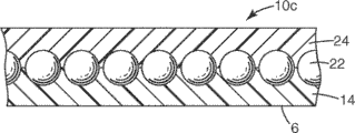
Fig. 5 illustrates another exemplary embodiment of the application type of lenticule sheet material 10c.In this embodiment; the lenticule sheet material is the sheet material 10c of " embedding lens " type; wherein microsphere lens 22 are embedded between transparency protected outer cover 24 (normally polymeric material) and the material layer 14 (also being the pearl adhesive layer usually, such as polymeric material).Material layer 14 comprises for the first surface 6 that receives donor material, below will be described in more detail this.U.S. Patent No. 3,801 has been described this based sheet among 183 (Sevelin etc.) in more detail, and different is to remove reflection horizon and cementing agent, and will again form layer 14 so that the more uncomfortable shape of curvature of itself and microsphere.
The lenticule of sheet material 10 preferably has the image that forms refracting element, to form image (will describe in more detail following); Usually be shaped as sphere by formation or the aspheric surface feature realizes this point.Other Available Material that graded index (GRIN) is provided not is to need inevitably curved surface to come refracted ray.Lenticule can have any symmetry, for example post symmetry or Sphere symmetry, and precondition is that refractive surface can form real image.Lenticule itself can be the lenticule of discrete form, for example circular plano-convex lenslet, circular biconvex lenslet, Fresnel lenslet, diffraction lenslet, clavate, microsphere, pearl or cylindrical lenslet.Can form the combination that lenticular material comprises glass, polymkeric substance, ore, crystal, semiconductor and these materials and other material.Also can use non-discrete lenticular lens elements.Therefore, also can use the lenticule that is formed by duplication process or imprint process (wherein the shape of sheet surface is changed, and has the profile that copies of imaging characteristic with formation).
Lenticule preferably has the uniform refractive index in from 1.4 to 3.0 scope of visible and infrared wavelength, and more preferably is in from 1.4 to 2.5 scope, although not necessarily.No matter each lenticule is discrete or copies also no matter lenticule by which kind of material is made, lenticular refractive power is preferably to incide on the first surface 6 that light on the optical element will focus on material layer 14 or in its vicinity.In certain embodiments, lenticule preferably the correct position on this layer form the real image dwindle.The structure of lenticule sheet material provides essential focused condition, so that focus in the modification and/or donor layer of separation with inciding energy approximation on the lenticule sheet material front surface, described modification and/or donor layer are preferably radiation-sensitive, and the below will be described in more detail this.
Although can use the lenticule of other size, lenticular diameter is preferably in 15 microns to 275 microns scope.For seeming the composograph relatively short with the isolated distance of microlens layer, use diameter can obtain good composograph resolution at the lenticule of above-mentioned scope lower limit, and for seeming the composograph relatively large with the isolated distance of microlens layer, use larger lenticule can obtain good composograph resolution.Other lenticule (for example lenslet size plano-convex, sphere or the non-spherical microlens suitable with specify being used for lenticular size) can be expected the similar optical results of generation.The cylindrical lens that the lenslet size is suitable with specify being used for lenticular size can be expected and produced similar optical results, although may need different or alternative image optics assembly.
As mentioned above, can with lenticule sheet material 10 in lenticule be adjacent to arrange material layer 14 among Fig. 3-5.The suitable material of the material layer 14 in the sheet material 10 comprises silicones, polyester, polyurethane, polycarbonate, polypropylene or any polymkeric substance that other can be made into sheet material or can be supported by substrate 8.In one exemplary embodiment, sheet material 10 can comprise microlens layer and the material layer of being made by different materials.For example, microlens layer can comprise acrylate, and material layer can comprise polyester.In other embodiments, sheet material 10 can comprise microlens layer and the material layer that is manufactured from the same material.For example, the lenticule of sheet material 10 and material layer can be formed by silicones, polyester, polyurethane, polycarbonate, polypropylene or any polymkeric substance that other can make sheet material, and can be by machine printed, copy or molded method forms.
In the first general embodiment of user interface as herein described, remove or ablation, phase place change or in the result of the coating polyreaction of the adjacent setting of a side of one or more microlens layers, can generate the image that appears in one's mind on the lenticule sheet material as change of component, material.Except details provided herein, also can be referring to U.S. Patent No. 6,288,842 (people such as Florczak), the disclosure of this patent is incorporated this paper by reference into.
In addition, for the second general embodiment of user interface as herein described, be used for forming the method for appearing image in one's mind at the lenticule sheet material and comprise that also the lenticule sheet material adds material.Except details provided herein, also referring to the U.S. Patent application No.2007/0081254 that announces people such as () Endle, the disclosure of this patent is incorporated herein by reference.
A. generate the composograph that appears in one's mind above sheet material
Referring to Fig. 6, incident radiation 100 (being light in this example) is guided and collimates by optical element 102, and optical element is with light 100b guiding divergent lens 105a.Light 100c disperses to lenticule sheet material 10 from divergent lens.
The light ray energy that is mapped to lenticule sheet material 10 roughly focuses on the interface between material layer 14 and the donor substrate (not shown) by each lenticule 4.This radiation that is focused causes radiosensitive shaped material in modification and/or the donor substrate and/or at least a portion generation modification and/or the conversion of colorant, form image 46 with the surface 6 at material layer 14, the size of image, shape and outward appearance depend on the reciprocation between light, lenticule and radiation-sensitive modification and/or the donor substrate.
Layout shown in Figure 7 will provide the sheet material with composograph, the observer seems that composograph appears above sheet material (as described below) in one's mind, because if divergent rays 100c passes lens and extends back, then can intersect at the focus 108a place of divergent lens.In other words, if the track of " image light " of supposition be by in the lenticule each from material layer, and return by divergent lens, they will be crossing at the 108a place of a part that presents composograph.
B. observe the composograph that appears in one's mind above sheet material
Can utilize from the observer homonymy (reflected light) or from the sheet material with observer's opposite side (transmitted light) or not only both had been mapped to the sheet material that visible light on the sheet material has composograph with observer's opposite side (transmitted light) from observer's homonymy (reflected light) but also from the sheet material.Fig. 7 is that observer A with the naked eye sees the synoptic diagram that appears the composograph above sheet material in one's mind when watching under reflected light.Naked eyes can be remedied to twenty-twenty vision, but can not otherwise be aided with (for example) magnifier or special viewer.The imaging sheet material may be collimated or during the irradiation of the reflected light of diffusion, light reflects from the imaging sheet material in the modes of being determined by the modification in each image 46 of light irradiation and/or donor material 42.According to definition, the image that is formed by modification and/or donor material 42 seems to be different from the non-imaging moiety of the material layer 14 that does not have modification and/or donor material 42, and therefore perceives image.
For example, the part of light L1 (for example, particular range of wavelengths) can be modified and/or donor material 42 reflects to the observer, its summation can form the color composite image that seems to appear in one's mind above sheet material, and the part of this image presents at the 108a place.In a word, as seen the specific part of electromagnetic spectrum can reflect from imaging moiety 46 reflections or from laminated substrate (for example passport (not shown)), and be imaged part 46 absorption or scatterings, this means that the part of color composite image will be apparent at the 108a place.Yet modification and/or donor material 42 may not can be reflected back the observer with reflection ray L2 well or not, and perhaps it may absorb the light that reflects and transmit by modification and/or donor material 42 subsequently from laminated surface in a large number.Therefore, the observer can detect the disappearance of 108a place light, and its summation can form one and appear the black composograph that presents in one's mind above sheet material, and its part is presented on the 108a place.In a word, light can partly reflect or from the laminates high reflection except imaging moiety 46 in the sheet material back, that is to say that relatively dark composograph will present at the 108a place from whole sheet material.
Also might will reflect or partially absorb incident light by image forming material 42, and will absorption optical with the blindstory compound (not shown) of imaging moiety 46 adjacent layouts, so that being provided, required contrast effect forms composograph.All the other of composograph under these situations and the sheet material with laminates (not shown) are compared and are seemed brighter, and it is relatively dark that other parts then seem.Can select as required the multiple combination of these possibility situations.
Some imaging sheet material also can pass through viewed in transmitted light, as shown in Figure 8.For example, if the imaging moiety of the modification on the material layer 14 and/or donor material 42 is translucent and absorbs a part in the visible spectrum, but not imaging moiety is transparent or translucent, but the height transmission, then some light L4 will be modified and/or donor material 42 optionally absorbs or reflects, not by lenticule towards guiding focus 108a.Other light L3 will be by at least part of transmission of non-imaging area.Composograph will be apparent at the focus place, in this example, compare with all the other of sheet material, and it is darker that composograph will seem, and be colored.In another exemplary embodiment, if the imaging moiety of the modification on the material layer 14 and/or donor material 42 is transparent or translucent, but height transmission, and non-imaging moiety be translucent and absorption or reflect visible light spectrum in a part, then some light L4 will be by the lenticule focus 108a that leads.Other light L3 will can be by non-imaging area transmission.Composograph will be apparent at the focus place, in this example, compare with all the other of sheet material, and it is brighter that composograph will seem, and be colored.
C. generate the composograph that appears in one's mind below sheet material
Also can form and seem on sheet material the composograph that suspends with observer's opposite side.Can replace the divergent lens 105a shown in Fig. 6 to generate with convergent lens and appear this image that appears in one's mind that below sheet material, appears in one's mind in one's mind.Referring to Fig. 9, projectile energy 100 (being light in this example) is guided and collimates by collimating apparatus 102, and collimating apparatus makes light 100b guiding convergent lens 105b.Light 100d out incides on the lenticule sheet material 10 between the focus 108b of convergent lens and convergent lens from convergent lens.
The energy that is mapped to the light of lenticule sheet material 10 roughly focuses in the interface area between material layer 14 and radiation-sensitive modification and/or the donor substrate (not shown) approximately by each lenticule 4.This radiation that is focused makes a part radiosensitive shaped material generation modification and/or the conversion in modification and/or the donor substrate, to form the image 46 that is made of modification and/or donor material 42, the size of image, shape and outward appearance depend on the reciprocation between light, lenticule sheet material and modification and/or the donor substrate.Layout shown in Figure 9 can provide the sheet material 10 with composograph, and the observer can see that composograph appears below sheet material (as described below) in one's mind, extends because if converging ray 100d passes sheet material, then can intersect at the focus 108b place of convergent lens.In other words, if begin to be passed in each lenticule and pass the track that image on the material layer that is formed by the modification that is associated with each lenticule and/or donor material 42 is drawn imaginary " image light " from convergent lens 105b, then these light will meet at the 108b place, present a part of composograph at this.
D. observe the composograph that appears in one's mind below sheet material
Also can under reflected light, transmitted light or reflected light and transmitted light, observe and have the sheet material that seems to appear in one's mind the composograph below sheet material.Figure 10 is the synoptic diagram that seems to appear in one's mind the composograph below sheet material under reflected light when watching.For example, can be by the part visible spectrum of the modification on the material layer 14 and/or donor material 42 absorption optical L5 or by its part visible spectrum to observer's reflected light L5.Therefore, the observer can detect the colored light that seems to be derived from 108b, and its summation can be created on the color composite image that the below of sheet material is appeared in one's mind, and its part presents at the 108b place.In a word, light can mainly be reflected from imaging moiety 46, this means that color composite image will be clearly at the 108b place.Alternatively, incident light can be by the reflection of the laminates of material layer back, and the part of light is modified subsequently and/or donor material 42 absorbs or scattering, and transmits to the observer.Therefore, the observer can detect and look like the colored light that is derived from 108b, and its summation will generate color composite image.In a word, light can and be imaged part 46 by the reflection of the laminates of material layer back and absorb, and this means that color composite image will be clearly at the 108b place.
Laminates that also might the material layer back can absorb incident light, and modification and/or donor material 42 will reflect respectively or partially absorb incident light, obtains composograph so that required contrast effect to be provided.Composograph under these situations is compared with all the other of sheet material and is seemed brighter, and it is relatively dark that other parts then seem.Can select as required the multiple combination of these possibility situations.
As shown in figure 11, also can watch by transmitted light L7 the sheet material of some imaging.For example, when the imaging moiety normal reflection on the material layer 14 of modification and/or donor material 42 or absorption color and do not have modification and/or the non-imaging moiety of donor material 42 when being transparent, then modification and/or donor material 42 will reflect or absorb the specific part of visible spectrum, and transmitted light will pass remaining not imaging moiety.These be absorbed or the light L8 (being called " image light " herein) that reflects along causing forming composograph with direction extension with the incident light opposite direction, the part of this image presents at the 108b place.Composograph will be clearly at the focus place, in this example, compare with the remainder of sheet material, and it is darker that composograph will seem, and be colored.
Alternatively,, the imaging moiety of the modification on the material layer 14 and/or donor material 42 has the height transmittance if being transparent or translucent, and the non-imaging moiety of material layer 14 is reflexive or at least part of absorptions, transmitted light in image-region will provide " image light " so, seem the composograph brighter than the remainder of sheet material with formation.
Composograph can look like (the meaning that they have length and width) of two dimension, can seem to be positioned at sheet material below, sheet material plane or sheet material top, perhaps looks like three-dimensional (meaning that they have length, width and height).As required, three-dimensional composograph can only seem below the sheet material above or below sheet material, in the sheet material plane and any combination above the sheet material.Term " in the sheet material plane " only refers to the plane of sheet material when sheet material keeps flat in general.That is, use this phrase place at this paper, concerning the sheet material of non-flat forms, also the composograph that seems at least partially in the plane of sheet material can be arranged.
Three-dimensional composograph can not be presented on each focus place, but presents as the composograph with continuous or discontinuous focus, and wherein focus extends to the point of opposite side from a side (or passing sheet material) of sheet material.This preferably realizes by following method: in order mobile relative to each other sheet material or radiation source (rather than by a plurality of different lens are provided) so that the material of a plurality of focuses place adjacent material layer improve and/or change, with synthetic image 46 on the surface 6 of material layer 14.The space combination picture that obtains comprises many each points substantially.This image can have spatial dimension in any one with respect to the sheet material plane in three Cartesian coordinatess.
In another kind of effect, composograph is moved in the zone of lenticule sheet material, composograph disappears in this zone.The job operation of this class image is processed to be similar to the mode of appearing the image example in one's mind, wherein sets up opaque mask before the microlens material, stops imaging light for the part of microlens material with the part.When observing this class image, image can be moved in the zone, contact mask reduces or eliminates imaging light in this zone.As if in this zone, image is " disappearance ".
In another kind of type of effect, composograph can the variable color with the variation at visual angle.Can adopt this class image of a kind of structure in the various ways, for example, in the first modification or the first donor at least one, the angle part of modularization image-forming radiation cone.Then, the same virtual image is by reimaging, makes that at least one has different colorants in the second modification or the second donor, thus the part of modular cone not before the modularization only.
The image that forms by process as herein described also can be configured to have the viewing angle of being limited to.In other words, only have from specific direction or from departing from the less angle of this direction and observe and just can see this image.
Optionally, user interface as herein described also comprises part transmission-type reflectance coating, and it is known in this area.Described film is the part or all of wavelength of reflect visible light spectrum partly.For example, if the reflectivity of all wavelengths is basic identical, then film will show the metal appearance of chromium or silver.Alternatively, if the degree of reflect yellow and ruddiness is stronger than reflect blue, then film will show the metal appearance of gold or copper well.Be adjusted to the reflectivity that is higher than other wavelength by the reflectivity with some wavelength, may show other color.For example, can realize this adjusting by the design film and/or by changing multi-coated interference film (for example, by adding dyestuff or pigment to the film of reflection all wavelengths and/or at film).
The exemplary embodiment of part transmission-type reflectance coating is very thin (namely, thickness is less than 100 nanometers, more typically less than 50 nanometers) metal (for example, chromium or aluminium) film and multi-coated interference film (referring to the textbook of for example being write by Macleod (Macleod 2001)).The exemplary embodiment of multi-coated interference film is plurality of layers of double refraction polymer film (referring to for example U.S. Patent No. 5,882,774 people such as () Jonza, the disclosure of this patent is incorporated herein by reference).The embodiment of these films is sold with " DBEF " trade mark by 3M company (St.Paul, MN).
Painted (for example, dyeing or band pigment) film is well known in the art and is commercially available.For example, available coloring film is that the trade mark of the 3M company of about 60 kinds of different colours is the film of " SCOTCHCAL 3630 ".In certain embodiments, colored reflectance coating also can use with coloring film, and the latter is put in observer's side, to realize required color control (for example, the gamut on the removal of images when producing the gamut background).
This paper employed " color shifting film " refers to comprise at least the film with the alternating layer of second layer type, wherein said ground floor type (for example comprises the strain hardening polymkeric substance, polyester), wherein said film has at least one transmission band and the zone of reflections in the visibility region of spectrum, the transmission band has at least 70% average transmittance, and at least one variation under the vertical incidence angle in wherein said transmission band and the zone of reflections is less than about per square inch 25nm.Optionally, film comprises the alternating polymer layer of at least the first and second layers of type, wherein film has at least one transmission band in the visibility region of spectrum and at least one zone of reflections, and wherein each of the belt edge of at least one in transmission band and the zone of reflections being changed in two orthogonal axles in the membrane plane under the vertical incidence angle is no more than 8nm at least two inches distance.Optionally, at least one in transmission band and the zone of reflections has being changed at 10cm at least under the vertical incidence angle
2Surf zone in be no more than the bandwidth of 2nm.Optionally, film just in time has a transmission band in the spectrum visibility region.Optionally, film just in time has a zone of reflections in the spectrum visibility region.
Can by for example (as) U.S. Patent No. 6,531,230 (people such as Weber) makes color shifting film describedly, the disclosure of this patent is incorporated herein by reference; In described patent, can also find the additional detail about this film.The embodiment of color shifting film is that 3M company (St.Paul, MN) is sold take " SCOTCHCAL 3630 " as trade mark.
" light control film " used herein refers to comprise the film of the overlay with first and second first type surfaces, and described the first first type surface has a plurality of grooves, makes the absorbed inside light of described groove.At for example U.S. Patent No. 4,621,898 (Cohen), No.5,204,160 (Rouser) and No.6 have described applicable light control film among 398,270 people such as () Chiu, and the disclosure of these patents is incorporated herein by reference.Optionally, the exemplary embodiment of light control film also comprises the cylindrical lens between the adjacent slot, and optionally, by at the inner light absorbent or inner with extinction printing ink treatment trough of filling of groove, makes groove absorbed inside light.
Film has the first type surface that is covered by bonding agent usually.Usually will find on a surface of film applicable bonding agent well known in the art (for example, contact adhesive), and allow film to be attached to another surface that described bonding agent is continuous or part according to related embodiment.
Some embodiment of light control film comprise: the first light-transmissive film, and it comprises more than first photo-absorption region that extends in its surface; The second light-transmissive film with the adjacent setting of the first light-transmissive film, it comprises more than second photo-absorption region that extends in its surface, wherein more than first photo-absorption region and more than second photo-absorption region are relatively located, so that the observer observes image by light controlling device in angular field of view, and prevention is observed image by light controlling device outside angular field of view.Optionally, more than first photo-absorption region comprises a plurality of grooves.Optionally, more than first and second photo-absorption region includes a plurality of grooves.
The hairline film provides the polymer film of wire drawing metal appearance.Described outward appearance not only can see, and comprises generally texture and wire drawing mark with the reality of wire drawing metal coupling.Described film also allows light therefrom to see through, so that the user can see the demonstration of film back, or sees the demonstration of film back by user interface.This class film can derive from for example Kaisei Kogyo company limited of Tokyo (for example, model is HSNO.1 (50 microns) film).
Applicable light emitting diode (LED) is known in the art and can be commercially available, comprises having the LED that 20 ° to the 30 ° light in the scope extract the LED of cone and have the lambertian optical transmission mode.LED can be used for various Rated running powers, comprises that scope is every LED less than 0.1 watt to 5 watts power (for example, Rated running power is up to 0.1,0.25,0.5,0.75,1,1.25,1.5,1.75 or even up to 2 watts).LED can be used for the color of scope from ultraviolet (about 410nm) to dark red (about 700nm).The Essential colour of LED is blue, green, red and amber, but also can obtain by the mixed base true qualities other color, such as white.
In certain embodiments, usually expectation, light emitting diode has consistent lumen output when being supplied to energy.In certain embodiments, the total use power of luminescence component as herein described up to 1 watt, 0.75 watt, perhaps even 0.5 watt, wherein in order to save power, usually more expectation be lower wattage, especially when with interface during for motor vehicles.If user interface is exposed to the strong surround lighting (for example, the sunshine direct projection) that may make the demonstration erosion, may needs higher power stage.
The applicable switch of user interface is known in the art and can be commercially available.After having read disclosure this moment, those skilled in the art can select to be applicable to the switch of particular user interface.
Optionally, for user interface as herein described, the first type surface of the sheet material relative with sensor has in protective finish, coating, antifogging coating or the antireflecting coating easy to clean at least one at least part of first type surface.
Optionally, the first type surface of the sheet material relative with sensor comprises the protective finish on it.Protective finish is known in the art, and is used to reduce scraping and the damage of substrate.Exemplary protective finish can comprise particle (for example, nano particle), with further increase wearing quality.Exemplary protective finish material is to be " 3M 906 ", " 3M SCOTCHGARD from the commercially available trade mark of 3M company (St.Paul, MN)
TMGRAPHIC AND SURFACE PROTECTION FILM 8991 " hard coat material, it is the polyester film of thick 0.1mm, has hard conating and has lasting contact adhesive for bonded substrate in exposure.
Optionally, the sheet material first type surface relative with sensor comprises coating easy to clean thereon.Coating easy to clean is known in the art, is used for getting rid of oil stain and spot, prevents from polluting and/or pollutant being absorbed into substrate.Exemplary coating material easy to clean comprises the material that contains fluorocarbon or highly cross-linked coating.Exemplary easy to clean/the anti-coating material of scribbling can be commercially available from Dow Corning (Midland, MI), its trade mark is " DOW CORNING 2601 ".
Optionally, the sheet material first type surface relative with sensor comprises antifogging coating thereon.Antifogging coating is known in the art, be used for to reduce or prevent from forming will scattered light water droplet, and alternatively, water is scattered in film, so can scattered beam.Exemplary antifogging coating material comprises the nano particle in the super hydrophile adhesive mass.Exemplary commercially available antifogging coating material comprises and can derive from Film Specialties Incorporated (Hillsborough, the trade mark of NJ are the coating material of " VISGARD " and " VISTEX ".
Optionally, the sheet material first type surface relative with sensor comprises antireflecting coating thereon.Antireflecting coating is known in the art, is used for causing from the destructive interference of the light wave of surface reflection, to eliminate reflection.Exemplary antireflection be configured in use low-refraction (UV curing) in the top fluoropolymer (for example, refractive index is about 1.4) crosslinking chemical and high index of refraction (for example, refractive index is about 1.7) hard conating (for example, being made by the compound of zirconium metal oxide cross-linked).
After having read disclosure this moment, those skilled in the art can use prior art design and assemble suitable optical assembly structure.
The embodiment of user interface as herein described is available, for example, as motor vehicle assembly (for example, instrument panel assemblies), electric appliance component (for example, dish-washing machine assembly, furnace module, baking oven assembly, micro-wave oven assembly, washing machine component and fabric dyeing machine assembly), Medical Devices, elevator push-button, laboratory equipment (for example, balance) and consumption electronic product (for example, amusement equipment or mobile phone), ATM (Automatic Teller Machine) etc.
Following example further illustrates advantage of the present invention and embodiment, but the concrete material of mentioning in these examples and quantity thereof and other conditions and details all should not be interpreted as inappropriate restriction of the present invention.Except as otherwise noted, otherwise all umbers and percentage number average by weight.
Example 1
The user interface of structure shown in Figure 12 and 13.Construct optically clear adhesive film, reflectivity multi-layer optical film, coloring film, have the film (wire drawing facing to the user) of the hairline outward appearance of wire drawing and the compound substance of imaging lenticule sheet material by following described mode, its modes of emplacement so that imaging reflective sheet side towards sensor 301 and LED 306.
The circuit diagram 250 that is used for user interface 299 has normal power supplies 251 (can be available from the Omron Corporation of kyoto, Japan, trade mark is " OMRON S8PS-30024C "), sensor amplifier 253 (can be available from the Keyence Corporation of Osaka, Japan, its trade mark is " KEYENCE FS-V21X "), the commutation diode 257 that is used for the shunting leakage current (can be available from the Nihon Inter Electronics Corporation of Kanagawa, Japan, its trade mark is " 10E1 ") and (can be available from the Ishizuka Electronics Corporation of Tokyo for the electric current adjusting diode 259 of control maximum current intensity, its trade mark is " CRDE103 "), programmable logic controller (PLC) 256 (can be available from Omron company limited, trade mark is " OMRON 20C2DR-D-V2 "), White LED 306a and green LED 306b (can be available from the Nichia Corporation of Japanese Tokushima, its trade mark is " NICHIA NSPW310BS " (White LED) and " NICHIA NSPG310B " (green LED)) and sensor 309 (can be available from Keyence Corporation, trade mark is " KEYENCE FU-22X ").Also can in parallelly use extra sensor amplifier (as 253), diode (as 257), versicolor LED (as 306a and 306b), sensor (as 301) and image (as 304), the extra White LED (as 306a) of use (all not shown) of also can connecting is to be used for extra virtual image button.
Use traditional laminated roller that the first optically clear adhesive film (sold by 3M company (St.Paul, MN), production code member is 8171) 315 is applied to the first first type surface of acrylic resin board (long 150mm, thick 3mm, wide 200mm) 310.Use traditional laminated roller that reflection multilayer blooming (trade mark of being sold by 3M company is the film of " Dual Brightness Enhancing Film Q " (" DBEF Q ")) the first first type surface of 305 is applied to the first type surface of the first optically clear adhesive film 315.Use traditional laminated roller that the second optically clear adhesive film (being sold by 3M company (St.Paul, MN)) 313 is applied to the second first type surface of reflection multilayer blooming.
Use traditional laminated roller that the first first type surface of coloring film 307 is applied on the first type surface of the second optically clear adhesive film 313.By the curable painted ink coats of conventional black UV is made coloring film 307 to 50 microns traditional polyester films.
Learn optical transparency binder film (3M company (St.Paul, MN) sells) 311 with the 3rd and be applied to the second first type surface of coloring film.The thick 50 microns film (can be available from Tokyo Kaisei Kogyo incorporated company, model is HSNO.1) 309 that uses traditional laminated roller will have wire drawing hairline outward appearance is applied to the first type surface of the 3rd optically clear adhesive film 311.Use traditional laminated roller the 4th optically clear adhesive film 317 to be applied to the second first type surface of acrylic resin board 310.
The lenticule sheet material (is sold by 3M company, trade mark is " SCOTCHLIGHT REFLECTIVE SHEETING 680-85 ") be such as U.S. Patent No. 6,288, the laser instrument of imaging described in the example 1 of 842 (people such as Florczak), the disclosure of this patent is incorporated herein by reference, different is (can be available from Bright Solutions (Cura Carpignano by laser instrument, Italy), trade mark is " WEDGE LASER "), the optical module that forms of beam expanding telescope and non-spherical lens.Concrete image is button, and (lateral dimension is 6mm * 22mm).Cut out aperture 302 (1.8mm), until the center of imaging button.Then, use traditional laminated roller that imaging reflective sheet 303 is applied to the 4th optically clear adhesive film 317.
By powering to user interface, the White LED 306 of display back is opened in initial setting up, presents the image that appears in one's mind that writes in the lenticule sheet material, and especially the white of button 304 is appeared image in one's mind.For this user interface, infrared sensor 301 can be according to the difference of passing the light quantity that aperture 302 returns, and detects near the variation that exists the user to point the image 304 to cause owing to appearing in one's mind.Change the first time that is detected by sensor 301 and will close White LED 306a and open green 306b, thereby the outward appearance that will appear image in one's mind becomes green from white.Change the second time that is detected by sensor 301 and will close green LED 306b and open White LED 306a, thereby the outward appearance that will appear image in one's mind becomes white from green.Ensuing each variation will make appear in one's mind image between green and white appearance alternately.
Example 2
The user interface 399 of structure as shown in Figure 14 and 15.Form the compound of the imaging lenticule sheet material that puts together towards one side, transparent resin layer 408 and the sensor chip 409 of acrylic resin board 407 and green LED 405 and red LED 406 with imaging reflective sheet 403 by following mode.This compound is to be configured to the user interface that Detection capacitance changes, for example by finger being put near the capacitance variations that produces the sensor region according to image 404 positions on the lenticule sheet material 403.
The power supply that the circuit diagram 350 of user interface 399 utilizes the conventional battery 410 from 9 volts to provide is provided, and described battery is also powered to sensor circuit by 5 volts voltage stabilizer 411 to green LED 405 and red LED 406 power supplies.Sensor circuit 420 comprises conductive sensor sheet 409, complementary metal oxide semiconductor (CMOS) (CMOS) the controller 412 ((Chandler of MicrochipTechnology company limited, AZ), trade mark is " PIC12F629212 ") and mos field effect transistor (MOSFET) 414 (can be available from Fairchild (South Portland, MA), trade mark is " 2N7002 ").
Around (20 square millimeters of transparent acrylic resin plates 407, thick 2mm) periphery is installed the green LED 405 of right angle emission and red LED 406 by surperficial mounting means, and (power of each is 0.1 watt, can be available from (the Palantine of Lumex incorporated company, IL), trade mark is respectively " SML-LXR851SIC-TR " and " SML-LXR851SUGC-TR ").Adhere to LED405,406 by the transparent organic silicon resin 408 that covers the routine on the sensor chip 409 with fitting shape.
Lenticule sheet material (sheet material of being sold with trade mark " SCOTCHLIGHT REFLECTIVE SHEETING 680-85 " by 3M company) is the laser instrument such as imaging as described in the above example 1, different is, image is that (lateral dimension is 17mm * 17mm) for different button.Utilize the adhesive-backed of lenticule sheet material (" SCOTCHLIGHT REFLECTIVE SHEETING 680-85 "), imaging lenticule sheet material is attached to the surface of acrylic resin board.The imaging features thing of lenticule back allows to pass imaging lenticule sheet material 403 and form image 404 from LED 405,406 light, and described image seems to appear in one's mind in the surface of user interface 399 or sinks to the lower face of user interface 399.
By to user interface power supply, the green LED 405 that lenticule sheet material 403 shows back is opened in initial setting up, present write in the lenticule sheet material 403 appear image 404 in one's mind.Capacitance type sensor circuit 350 can be according to the variation of electric capacity on the sensor chip 409, detects near the variation that exists the user to point the image 404 to cause owing to appearing in one's mind.Change the first time that detects and will open red LED 406, the outward appearance that therefore will appear image 404 in one's mind becomes bright orange from green.Change the second time that detects and will close red LED 406, the outward appearance that therefore will appear image 404 in one's mind becomes green from bright orange.Ensuing each variation will make the outward appearance of appearing image 404 in one's mind replace between green and bright orange.
Example 3
Such as ground structuring user's interface as described in the example 2, different is, the imaging that has a radiation-sensitive layer 510 (505,507 and 509 overall) at the first type surface 512 of the substantitally planar of lenticule sheet material 503 copies lenticule sheet material 501 and is attached to acrylic resin board 407.Referring to Figure 16, radiation-sensitive layer 510 (following described) with layer 505,507 and 509 is that tuning multilayer optical is stacking, as U.S. Patent No. 7,336, among 422 people such as () Dunn report like that, the disclosure of this patent is incorporated herein by reference.This compound is to be configured to the user interface that Detection capacitance changes, and for example finger is put near the capacitance variations that produces the sensor region according to image 404 positions on the lenticule sheet material 403.
Radiation-sensitive layer 510 is to stack (that is, layer 505,507,509) by the multilayer optical that vacuum moulding machine prepares, and wherein said layer is applied to the face 512 of the substantitally planar of the lenticule sheet material 503 that copies.By vacuum sputtering the metal ground floor of chromium (thickness is about 5nm) 505 is applied to first type surface 506 (referring to U.S. Patent No. 5,877, the example of 895 (people such as Shaw), the disclosure of this patent is incorporated herein by reference).By vacuum evaporation the second layer 507 (thickness is about 400nm) is applied to ground floor 505, and then use the concentrated and polymerization tripropylene glycol diacrylate of 2% light trigger (2-hydroxy-2-methyl-phenyl-propane-1-ketone) (referring to U.S. Patent No. 5,877, the example of 895 (people such as Shaw), the disclosure of this patent is incorporated herein by reference).Use the 3rd layer 509 (the about 80nm) that aluminum metal makes (referring to U.S. Patent No. 5,877, the example of 895 (people such as Shaw), the disclosure of this patent is incorporated herein by reference) by vacuum sputtering at the second layer 507.
As described in example 1, be written in as described in Figure 16 the lenticule sheet material with the image that appears in one's mind of same process with another button feature thing.Compound in the example 3 uses imaging to copy the imaging lenticule sheet material (403) that the lenticule sheet material replaces example 2.Use translucent white double-sided adhesive band that imaging lenticule sheet material is attached to sensor chip 409.
As the mode among Fig. 7, before to the sensor circuit power supply, can observe with Ambient and copy the characteristics of image thing of lenticule sheet material back, its outward appearance is the image that appears in one's mind of silver color.As the mode among Fig. 8, to after the sensor circuit power supply and opening green LED, can copy with the viewed in transmitted light from green LED the characteristics of image thing of lenticule sheet material back, its outward appearance is the green image that appears in one's mind.When sensor detected variation on the sensor chip (for example, finger is positioned at the position of appearing image in one's mind), sensor circuit detected capacitance variations and opens red LED.The light that sends from the combination of green LED and red LED will become bright orange to the outward appearance of appearing image in one's mind from green.Detect to change for the second time and will close red LED 406, the outward appearance that therefore will appear image in one's mind becomes green from bright orange.Each variation subsequently will make the outward appearance of appearing image in one's mind replace between green and bright orange.Then, with the sensor circuit outage, the characteristics of image thing that copies lenticule sheet material back reverts to the picture appearance of appearing in one's mind of silver color.
Example 4
The user interface for preparing example 4 by example 3 describedly, different is, the imaging that replaces having radiation-sensitive layer 510 with the imaging lenticule sheet material described in the example 1 of U.S. Patent application No.2007/0081254 people such as () Endle copies lenticule sheet material 503, the disclosure of this patent is incorporated herein by reference, different is, (can be available from Bright Solutions (Cura Carpignano by laser instrument, Italy), trade mark is " WEDGE LASER "), the optical module that forms of beam expanding telescope and non-spherical lens.Appearing image in one's mind is cyan, and uses translucent white double-sided adhesive band that imaging lenticule sheet material is attached to sensor chip 409.
As the mode among Fig. 7, before to the sensor circuit power supply, can observe with Ambient and copy the characteristics of image thing of lenticule sheet material back, its outward appearance is that the cyan on the diffusion white background is appeared image in one's mind.As the mode among Fig. 8, to after sensor circuit power supply and opening green LED, can copy the cyan image feature of lenticule sheet material back observing from the green background of the light of green LED.When sensor detects variation on the sensor chip when (for example, finger position appears the position of image in one's mind), sensor circuit will detect the variation of electric capacity and open red LED.To become bright orange to the outward appearance of appearing image background in one's mind from green from the light of the combined transmit of green LED and red LED.Detect to change for the second time and will close red LED 406, thereby the outward appearance of appearing image background in one's mind becomes green from bright orange.Each variation subsequently will make the background outward appearance of appearing image in one's mind replace between green and bright orange.Then, with sensor circuit outage, and copy the cyan that the outward appearance of the characteristics of image thing of lenticule sheet material back is reduced on the diffusion white background and appear image in one's mind.
Example 5
The user interface that described in example 3, prepares example 5, different is to replace sensor 301, aperture 302, imaging reflective sheet 303 and button 304 with the structure shown in Figure 17 (wherein having sensor 601, imaging reflective sheet 603 and button 604 (not having corresponding aperture)).In this example, the sensing region of the sensor 601 of preparation overlaps with button 604.For this user interface, infrared sensor 601 can detect the variation that is caused by near user's (for example, user's finger is positioned at and appears in one's mind the image 604) according to the light quantity that is back to sensor 601.
Example 6 (imaginary example)
As preparing the user interface of example 6 as described in the example 3, different is, use the structure shown in Figure 18 (wherein showing infrared transmission sensor element 701a and receiving sensor element 701b (can be available from for example Keyence Corporation, trade mark is " KEYENCE FU-32 "), imaging reflective sheet 703 and button 704 (not having corresponding aperture)) to replace sensor 301, aperture 302, imaging reflective sheet 303 and button 304.Transmission sensor element 701a can be mounted to receiving sensor element 701b and aim at, so that image 7604 is between the two.For this user interface, infrared transmission sensor element 701a and receiving sensor element 701b can according to the variation that is transmitted to the light quantity of receiving sensor element 701b from transmission sensor element 701a, detect owing to user's finger is present in and appear near the variation that causes the image 704 in one's mind.
Exemplary user interfaces embodiment
1. user interface comprises:
Sensor;
Sheet material, it comprises:
At least one microlens layer, it has first surface and second;
Material layer, the adjacent setting of first surface of itself and described microlens layer;
At least part of complete image, in the material that it is formed on each lenticule in a plurality of described lenticules is associated, wherein said image and described material form contrast; And
Composograph, it is formed by each image, with the naked eye sees, at least one during described composograph appears in one's mind above or below described sheet material,
Wherein, described sensor and described sheet material are arranged to, so that carry out starting described sensor when mutual when user and the described composograph that appears in one's mind.
2. such as the user interface among the embodiment 1, wherein said material is radiosensitive shaped material.
3. such as the user interface in embodiment 1 and 2, wherein said material is metal radiation responsive type material.
4. such as the user interface among the embodiment 3, wherein said metal radiation responsive type material is selected from alloy and the combination thereof of aluminium, silver, copper, gold, titanium, zinc, tin, chromium, vanadium, tantalum, these metals.
5. such as the user interface among the embodiment 1, wherein said material is non-metal radiation responsive type material.
6. such as the user interface among the embodiment 5, wherein said nonmetal radiosensitive shaped material is selected from zinc sulphide, zinc selenide, silicon dioxide, indium tin oxide, zinc paste, magnesium fluoride, silicon and combination thereof.
7. such as the user interface among the embodiment 1, wherein said material is the compound of radiation-sensitive metal oxide.
8. such as the user interface among the embodiment 7, the compound-material of wherein said radiation-sensitive metal oxide is selected from alumina cpd, iron oxide compound, cupric oxide compound, tin oxide compound and chromium oxide compounds.
9. such as the user interface among the embodiment 1, wherein said material is the radiosensitive shaped material of thermochromism.
10. such as the user interface among the embodiment 9, the radiosensitive shaped material of wherein said thermochromism is selected from copper carbonate, contains the copper carbonate of the copper nitrate of thiocarbamide, sulfur-bearing, hydration sulfuric acid, boron nitride, aluminium nitride, nitrogenize bismuth and combination thereof, and described sulphur comprises the compound of mercaptan, thioether, sulfoxide and sulfone.
11. such as the user interface among the embodiment 1, wherein said material is the radiosensitive shaped materials of multilayer film.
12. as before user interface among the embodiment any, also comprise the wall that is arranged between described material layer and the described lenticule.
13. as before user interface among the embodiment any, wherein said lenticule is selected from plano-convex lenslet, circular biconvex lenslet, bar, microsphere, pearl or cylindrical lenslet and their combination.
14. as before user interface among the embodiment any, wherein said composograph is to be visible in the whole visual angles less than 100 degree.
15. a user interface comprises:
Sensor;
Sheet material, described sheet material comprises:
Microlens array;
Material layer, described material layer is adjacent with described microlens array;
In first material modified or the first donor material that contacts with described material layer at least one, in wherein said first material modified or the first donor material at least one forming the complete image of various piece with each described material layer that is associated in a plurality of described lenticules, wherein said sheet material presents the composograph that is formed by described each image, with the naked eye see, during described composograph seems to appear in one's mind above or below described sheet material at least one
Wherein, described sensor and described sheet material are arranged to, so that carry out starting described sensor when mutual when user and the described composograph that appears in one's mind.
16. such as the user interface among the embodiment 15, wherein at least part of described composograph is at least a in fluorescence or the phosphorescence, and naked eyes seem to appear in one's mind above described sheet material.
17. such as the user interface among the embodiment 15, wherein at least part of described composograph is at least a in fluorescence or the phosphorescence, and naked eyes seem to appear in one's mind below described sheet material.
18. such as the user interface among the embodiment 15, wherein at least part of described composograph is at least a in fluorescence or the phosphorescence, and naked eyes seem to appear in one's mind the above and below at described sheet material.
19. such as the user interface among any embodiment among the embodiment 15 to 18, at least one in wherein said the first modification or the first donor material comprises colorant.
20. such as the user interface among the embodiment 19, wherein at least part of described composograph present with described the first modification or the first donor material at least one in the close color of described colorant.
21. such as the user interface among any embodiment among the embodiment 15 to 20, at least one in wherein said the first modification or the first donor material comprises radiosensitive shaped material.
22. such as the user interface among any embodiment among the embodiment 15 to 20, at least one in wherein said the first modification or the first donor material comprises metal radiation responsive type material.
23. such as the user interface among any embodiment among the embodiment 15 to 20, at least one in wherein said the first modification or the first donor material comprises nonmetal radiosensitive shaped material.
24. such as the user interface among any embodiment among the embodiment 15 to 23, wherein in the whole visual angle less than 150 degree, described composograph is visible.
25. such as the user interface among any embodiment among the embodiment 15 to 24, wherein with respect to the visual angle less than 150 degree, the color of described composograph changes.
26. such as the user interface among any embodiment among the embodiment 15 to 25, wherein said composograph is two dimensional image.
27. such as the user interface among any embodiment among the embodiment 15 to 25, wherein said composograph is 3-D view.
28. such as the user interface among any embodiment among the embodiment 15 to 27, also comprise second modification adjacent with described material layer or in the second donor material at least one, at least one in wherein said the second modification or the second donor material described sheet material form with a plurality of lenticules in the complete image of each various piece that is associated.
29. such as the user interface among the embodiment 28, at least one in wherein said the second modification or the second donor material comprises colorant, described colorant is different from the colorant in described the first modification or the first donor material at least one.
30. such as the user interface among the embodiment 29, wherein said at least part of composograph present with described the first modification or the first donor material at least one in colorant and the close color of the colorant in described the second modification or the second donor material at least one.
31. such as the user interface among the embodiment 29, wherein said at least part of composograph present with described the first modification or the first donor material at least one in colorant and the close color of the potpourri of the colorant in described the second modification or the second donor material at least one.
32. such as the user interface among the embodiment 29, in wherein said the first modification or the first donor material at least one comprises colorant and forms the first composograph, and at least one in wherein said the second modification or the second donor material forms the second composograph, and it is at least a in fluorescence or the phosphorescence.
33. such as the user interface among any embodiment among the embodiment 15 to 32, also comprise for the adhesive phase that described sheet material is applied to substrate.
34. sheet material as described in example 33 above, wherein said sheet material is adhered in the substrate.
35. user interface is as described in example 15 above wherein with the naked eye seen, described composograph is also at least part of plane that is presented on described sheet material.
36. such as the user interface among any embodiment among the embodiment 1 to 35, wherein said composograph presents under reflected light, to appear in one's mind above sheet material.
37. such as the user interface among any embodiment among the embodiment 1 to 35, wherein said composograph presents under reflected light, to appear in one's mind below sheet material.
38. such as the user interface among any embodiment among the embodiment 1 to 35, wherein said composograph presents under reflected light, to appear the above and below at described sheet material in one's mind.
39. such as the user interface among any embodiment among the embodiment 1 to 35, wherein said composograph presents in transmitted light, to appear in one's mind above described sheet material.
40. such as the user interface among any embodiment among the embodiment 1 to 35, wherein said composograph presents in transmitted light, to appear in one's mind below described sheet material.
41. such as the user interface among any embodiment among the embodiment 1 to 35, wherein said composograph presents in transmitted light, to appear the above and below at described sheet material in one's mind.
42., it seems with the naked eye wherein that described composograph is at least part of to be presented in the plane of described sheet material such as the user interface among any embodiment among the embodiment 1 to 35.
43. such as the user interface among any embodiment among the embodiment 1 to 35, wherein said sheet material is to expose lens sheet.
44. such as the user interface among any embodiment among the embodiment 1 to 35, wherein said sheet material is to embed lens sheet.
45. such as the user interface among any embodiment among the embodiment 1 to 35, wherein when the position of observing changed with respect to sheet material, described composograph seemed to move with respect to described sheet material.
46. such as the user interface among any embodiment among the embodiment 1 to 35, wherein when observing the visual angle change of sheet material, described composograph disappears and reappears.
47. such as the user interface among any embodiment among the embodiment 1 to 35, wherein said sheet material comprises a more than composograph.
48. such as the user interface among any embodiment among the embodiment 1 to 35, wherein said sensor is infrared sensor, and has opening in the wherein said sheet material, is used for seeing through sheet material by described infrared ray sensor and detects.
49. such as the user interface among any embodiment among the embodiment 1 to 35, wherein said sensor is capacitance type sensor.
50. such as the user interface among any embodiment among the embodiment 1 to 49, also comprise part transmission-type reflectance coating, described sensor, sheet material and film set gradually by described order.
51. the user interface as among any embodiment among the embodiment 1 to 49 also comprises:
Coloring film; And
Part transmission-type reflectance coating,
Wherein said sensor, described sheet material, described coloring film and described part transmission-type reflectance coating set gradually by described order.
52. the user interface as among any embodiment among the embodiment 1 to 49 also comprises:
Color shifting film; And
Part transmission-type reflectance coating,
Wherein said sensor, described sheet material, described color shifting film and described part transmission-type reflectance coating set gradually by described order.
53. the user interface as among any embodiment among the embodiment 1 to 49 also comprises:
Coloring film;
Part transmission-type reflectance coating; And
Light control film;
Wherein, described sensor, described sheet material, described coloring film, described part transmission-type reflectance coating and described light control film set gradually by described order.
54. the user interface as among any embodiment among the embodiment 1 to 49 also comprises:
Color shifting film;
Part transmission-type reflectance coating; And;
Light control film,
Wherein said sensor, described sheet material, described color shifting film, described part transmission-type reflectance coating and described light control film set gradually by described order.
55. such as the user interface among any embodiment among the embodiment 1 to 54, also comprise for the switch that will device starts into on-mode.
56. such as the user interface among any embodiment among the embodiment 1 to 54, also comprise for the switch that will device starts into the pass pattern.
57. such as the user interface among any embodiment among the embodiment 1 to 54, also comprise for device is started into the switch of opening and close pattern.
58. such as the user interface among any embodiment among the embodiment 1 to 57, also comprise light source, wherein said light source, described sensor and described sheet material set gradually by described order.
59. such as the user interface among the embodiment 58, wherein said light source comprises light emitting diode.
60. such as the user interface among any embodiment among the embodiment 1 to 59, wherein said sheet material has the first type surface relative with described sensor, comprises protective coating at least part of described first type surface.
61. such as the user interface among any embodiment among the embodiment 1 to 60, wherein said sheet material has the first type surface relative with described sensor, comprises coating easy to clean at least part of described first type surface.
62. such as the user interface among any embodiment among the embodiment 1 to 61, wherein said sheet material has the first type surface relative with described sensor, comprises antifogging coating at least part of described first type surface.
63. such as the user interface among any embodiment among the embodiment 1 to 62, wherein said sheet material has the first type surface relative with described sensor, has antireflecting coating at least part of described first type surface.
64. such as the user interface among any embodiment among the embodiment 1 to 63, described user interface is motor vehicle assembly.
65. such as the user interface among any embodiment among the embodiment 1 to 64, described user interface is the automobile instrument panel assembly.
66. such as the user interface among any embodiment among the embodiment 1 to 63, described user interface is electric appliance component.
67. such as the user interface among any embodiment among the embodiment 1 to 63, described user interface is the dish-washing machine assembly.
68. such as the user interface among any embodiment among the embodiment 1 to 63, described user interface is furnace module.
69. such as the user interface among any embodiment among the embodiment 1 to 63, described user interface is the baking oven assembly.
70. such as the user interface among any embodiment among the embodiment 1 to 63, described user interface is the micro-wave oven assembly.
71. such as the user interface among any embodiment among the embodiment 1 to 63, described user interface is washing machine component.
72. such as the user interface among any embodiment among the embodiment 1 to 63, described user interface is the fabric dyeing machine assembly.
73. such as the user interface among any embodiment among the embodiment 1 to 63, described user interface is the consumer electronics assembly.
The various modification of disclosed embodiment of this invention and combination all are apparent to one skilled in the art, and the scope of the present invention that appended claims limits is intended to comprise these modification.
Claims (15)
1. user interface, it comprises:
Sensor;
Sheet material comprises:
At least one microlens layer, described microlens layer have first surface and second;
Material layer is with the adjacent setting of described first surface of described microlens layer;
At least part of complete image that forms in described material is associated with in a plurality of described lenticules each, and wherein said image and described material form contrast; And
By the composograph that each image forms, with the naked eye see, at least one during described composograph seems to appear in one's mind above or below described sheet material,
Wherein, described sensor and described sheet material are arranged to, so that carry out starting described sensor when mutual when user and the described composograph that appears in one's mind.
2. user interface according to claim 1, wherein said material is radiosensitive shaped material.
3. user interface according to claim 1 also comprises wall, and described wall is arranged between described material layer and the described lenticule.
4. according to each the described user interface in the claim before, wherein in the whole visual angles less than 100 degree, described composograph is visible.
5. user interface, it comprises:
Sensor;
Sheet material comprises:
Microlens array;
Material layer is adjacent with described microlens array;
The first modification that contacts with described material layer or in the first donor material at least one, in wherein said the first modification or the first donor material at least one described material layer form with a plurality of described lenticules in the complete image of each various piece that is associated, wherein said sheet material presents the composograph that is formed by each image, with the naked eye see, during described composograph appears in one's mind above or below described sheet material at least one
Wherein, described sensor and described sheet material are arranged to, so that carry out starting described sensor when mutual when user and the described composograph that appears in one's mind.
6. user interface according to claim 5, wherein at least part of described composograph is at least a in fluorescence or the phosphorescence, and with the naked eye seem to appear in one's mind above the described sheet material, described sheet material below or appear above and below at described sheet material in one's mind.
7. user interface according to claim 5, at least one in wherein said the first modification or the first donor material comprises radiosensitive shaped material.
8. user interface according to claim 5, wherein with respect to the visual angles less than 150 degree, the color of described composograph changes.
9. user interface according to claim 5, also comprise second modification adjacent with described material layer or in the second donor material at least one, at least one in wherein said the second modification or the second donor material described sheet material form with a plurality of described lenticules in the complete image of each various piece that is associated.
10. each described user interface in 3 and 5 to 9 according to claim 1, wherein said sensor is infrared sensor, and has opening in the wherein said sheet material, is used for seeing through described sheet material by described infrared sensor and detects.
11. each described user interface in 3 and 5 to 9 also comprises part transmission-type reflectance coating according to claim 1, wherein said sensor, described sheet material and described film set gradually by described order.
12. each described user interface in 3 and 5 to 9 according to claim 1 also comprises:
Coloring film or color shifting film; And
Part transmission-type reflectance coating;
Wherein, described sensor, described sheet material, described coloring film or color shifting film and described part transmission-type reflectance coating set gradually by described order.
13. each described user interface in 3 and 5 to 9 according to claim 1 also comprises:
Coloring film or color shifting film
Part transmission-type reflectance coating; And
Light control film,
Wherein said sensor, described sheet material, described coloring film or color shifting film, described part transmission-type reflectance coating and described light control film set gradually by described order.
14. each described user interface in 3 and 5 to 9 also comprises light source according to claim 1, wherein said light source, described sensor and described sheet material set gradually by described order.
15. each described user interface in 3 and 5 to 9 according to claim 1; wherein said sheet material has the first type surface relative with described sensor, comprises protective coating, coating, antifogging coating or antireflecting coating easy to clean at least part of described first type surface.
Applications Claiming Priority (3)
| Application Number | Priority Date | Filing Date | Title |
|---|---|---|---|
| US15882709P | 2009-03-10 | 2009-03-10 | |
| US61/158,827 | 2009-03-10 | ||
| PCT/US2010/026621 WO2010104827A1 (en) | 2009-03-10 | 2010-03-09 | User interface with a composite image that floats |
Publications (1)
| Publication Number | Publication Date |
|---|---|
| CN202661719U true CN202661719U (en) | 2013-01-09 |
Family
ID=42125008
Family Applications (1)
| Application Number | Title | Priority Date | Filing Date |
|---|---|---|---|
| CN2010900008761U Expired - Fee Related CN202661719U (en) | 2009-03-10 | 2010-03-09 | User interface having projected synthetic image |
Country Status (5)
| Country | Link |
|---|---|
| US (1) | US9268146B2 (en) |
| JP (1) | JP2012520508A (en) |
| CN (1) | CN202661719U (en) |
| DE (1) | DE112010001150T5 (en) |
| WO (1) | WO2010104827A1 (en) |
Cited By (1)
| Publication number | Priority date | Publication date | Assignee | Title |
|---|---|---|---|---|
| CN114546180A (en) * | 2021-10-07 | 2022-05-27 | 达运精密工业股份有限公司 | Floating image generating device and floating image touch device |
Families Citing this family (6)
| Publication number | Priority date | Publication date | Assignee | Title |
|---|---|---|---|---|
| EP2363055A1 (en) | 2010-03-01 | 2011-09-07 | Electrolux Home Products Corporation N.V. | Projector and household appliance comprising such a projector |
| US8665523B2 (en) | 2011-09-12 | 2014-03-04 | 3M Innovative Properties Company | Multilayer 3D floating images in a single substrate |
| CN103513707A (en) * | 2012-06-26 | 2014-01-15 | 富泰华工业(深圳)有限公司 | Electronic device with mirror function |
| KR102376226B1 (en) * | 2013-05-20 | 2022-03-17 | 가부시키가이샤 한도오따이 에네루기 켄큐쇼 | Semiconductor device |
| ES2780973T3 (en) * | 2017-05-24 | 2020-08-27 | Flex Automotive Gmbh | Device, system and procedure for the representation of a floating light symbol |
| EP3556702A1 (en) | 2018-03-13 | 2019-10-23 | Otis Elevator Company | Augmented reality car operating panel |
Family Cites Families (36)
| Publication number | Priority date | Publication date | Assignee | Title |
|---|---|---|---|---|
| US3801183A (en) | 1973-06-01 | 1974-04-02 | Minnesota Mining & Mfg | Retro-reflective film |
| US4621898A (en) | 1983-03-17 | 1986-11-11 | Allied Corporation | Directional optical filter |
| US5204160A (en) | 1988-08-08 | 1993-04-20 | Minnesota Mining And Manufacturing Company | Light-collimating film |
| CA2062608A1 (en) * | 1991-04-18 | 1992-10-19 | Steven W. Tanamachi | Two-part sensor with transformer power coupling and optical signal coupling |
| CA2160245C (en) * | 1993-04-28 | 2005-09-20 | R. Douglas Mcpheters | Holographic operator interface |
| DE69432283T2 (en) * | 1993-12-01 | 2004-01-22 | Sharp K.K. | Display for three-dimensional images |
| US5882774A (en) | 1993-12-21 | 1999-03-16 | Minnesota Mining And Manufacturing Company | Optical film |
| US5828488A (en) | 1993-12-21 | 1998-10-27 | Minnesota Mining And Manufacturing Co. | Reflective polarizer display |
| JPH08153940A (en) | 1994-11-25 | 1996-06-11 | Kanegafuchi Chem Ind Co Ltd | Flexible circuit board |
| US5877895A (en) | 1995-03-20 | 1999-03-02 | Catalina Coatings, Inc. | Multicolor interference coating |
| US6214034B1 (en) * | 1996-09-04 | 2001-04-10 | Radiancy, Inc. | Method of selective photothermolysis |
| US6531230B1 (en) | 1998-01-13 | 2003-03-11 | 3M Innovative Properties Company | Color shifting film |
| JP3536144B2 (en) | 1999-05-06 | 2004-06-07 | 東拓工業株式会社 | Corrugated pipe fittings |
| US6288842B1 (en) * | 2000-02-22 | 2001-09-11 | 3M Innovative Properties | Sheeting with composite image that floats |
| US7336422B2 (en) | 2000-02-22 | 2008-02-26 | 3M Innovative Properties Company | Sheeting with composite image that floats |
| GB0017008D0 (en) * | 2000-07-12 | 2000-08-30 | Street Graham S B | Structured light source |
| US6398370B1 (en) | 2000-11-15 | 2002-06-04 | 3M Innovative Properties Company | Light control device |
| US6478432B1 (en) * | 2001-07-13 | 2002-11-12 | Chad D. Dyner | Dynamically generated interactive real imaging device |
| AU2004258513B2 (en) | 2003-07-03 | 2009-12-24 | Holotouch, Inc. | Holographic human-machine interfaces |
| US7342705B2 (en) * | 2004-02-03 | 2008-03-11 | Idc, Llc | Spatial light modulator with integrated optical compensation structure |
| EA012512B1 (en) * | 2004-04-30 | 2009-10-30 | Де Ля Рю Интернэшнл Лимитед | A security device and method of manufacturing thereof |
| US7616332B2 (en) | 2004-12-02 | 2009-11-10 | 3M Innovative Properties Company | System for reading and authenticating a composite image in a sheeting |
| US20070014020A1 (en) | 2005-07-13 | 2007-01-18 | Eastman Kodak Company | Low birefringent light redirecting film |
| US8243125B2 (en) | 2005-07-25 | 2012-08-14 | Pioneer Corporation | Image display device |
| JP4651672B2 (en) | 2005-08-05 | 2011-03-16 | パイオニア株式会社 | Image display device |
| US7981499B2 (en) | 2005-10-11 | 2011-07-19 | 3M Innovative Properties Company | Methods of forming sheeting with a composite image that floats and sheeting with a composite image that floats |
| JP2007194341A (en) | 2006-01-18 | 2007-08-02 | Kyocera Chemical Corp | Flexible printed wiring board and manufacturing method thereof |
| US7609452B2 (en) * | 2006-06-12 | 2009-10-27 | Guardian Industries Corp. | 3D gauge face for vehicle dashboard |
| US20080027199A1 (en) | 2006-07-28 | 2008-01-31 | 3M Innovative Properties Company | Shape memory polymer articles with a microstructured surface |
| US7800825B2 (en) | 2006-12-04 | 2010-09-21 | 3M Innovative Properties Company | User interface including composite images that float |
| JP4845705B2 (en) | 2006-12-19 | 2011-12-28 | 日東電工株式会社 | Printed wiring board, manufacturing method thereof, and electronic device |
| FI2165224T3 (en) | 2007-07-11 | 2024-01-11 | Thales Dis France Sas | Sheeting with composite image that floats |
| US20090034083A1 (en) * | 2007-07-30 | 2009-02-05 | Micron Technology, Inc. | Method of forming a microlens array and imaging device and system containing such a microlens array |
| EP2223174A4 (en) | 2007-11-27 | 2014-05-28 | 3M Innovative Properties Co | Methods for forming sheeting with a composite image that floats and a master tooling |
| US7995278B2 (en) | 2008-10-23 | 2011-08-09 | 3M Innovative Properties Company | Methods of forming sheeting with composite images that float and sheeting with composite images that float |
| US8149351B2 (en) | 2008-12-08 | 2012-04-03 | 3M Innovative Properties Company | Passive and hybrid daylight-coupled backlights for sunlight viewable displays |
-
2010
- 2010-03-09 CN CN2010900008761U patent/CN202661719U/en not_active Expired - Fee Related
- 2010-03-09 US US13/255,532 patent/US9268146B2/en not_active Expired - Fee Related
- 2010-03-09 DE DE112010001150T patent/DE112010001150T5/en not_active Withdrawn
- 2010-03-09 WO PCT/US2010/026621 patent/WO2010104827A1/en not_active Ceased
- 2010-03-09 JP JP2011554112A patent/JP2012520508A/en active Pending
Cited By (2)
| Publication number | Priority date | Publication date | Assignee | Title |
|---|---|---|---|---|
| CN114546180A (en) * | 2021-10-07 | 2022-05-27 | 达运精密工业股份有限公司 | Floating image generating device and floating image touch device |
| CN114546180B (en) * | 2021-10-07 | 2024-04-26 | 达运精密工业股份有限公司 | Floating image generating device and floating image touch device |
Also Published As
| Publication number | Publication date |
|---|---|
| DE112010001150T5 (en) | 2012-05-16 |
| WO2010104827A1 (en) | 2010-09-16 |
| JP2012520508A (en) | 2012-09-06 |
| US9268146B2 (en) | 2016-02-23 |
| US20120002292A1 (en) | 2012-01-05 |
Similar Documents
| Publication | Publication Date | Title |
|---|---|---|
| CN202661719U (en) | User interface having projected synthetic image | |
| KR101827468B1 (en) | Graphic image display for operation with backlight and/or ambient light | |
| US8094376B2 (en) | Multi-layer body with micro-lens arrangement | |
| EP2008129B1 (en) | Sheeting with composite image that floats | |
| CN109073952A (en) | Hybrid reflective-emissive image display | |
| TW201235692A (en) | Microlens laminate capable of providing floating image | |
| KR20160003092A (en) | Multi-layered solar cell device | |
| CN109919103A (en) | Biological characteristic detects mould group and backlight module and electronic device | |
| CN213519967U (en) | Display device and electronic apparatus | |
| CN213519977U (en) | Display device, detection module, image module and electronic equipment | |
| CN109902653A (en) | Biological characteristic detects mould group and backlight module and electronic device | |
| CN213519965U (en) | Display device, detection module, image module and electronic equipment | |
| CN213184289U (en) | Display device, detection module and electronic equipment | |
| JP7744402B2 (en) | display device | |
| CN213519969U (en) | Display device, detection module and electronic equipment | |
| CN213519976U (en) | Display device, detection module and electronic equipment | |
| CN213519958U (en) | Display device, detection module and electronic equipment | |
| CN213519962U (en) | Display device, detection module, image module and electronic equipment | |
| CN213519961U (en) | Display device and electronic apparatus | |
| CN215008235U (en) | Display device, detection module and electronic equipment | |
| CN213519959U (en) | Display device, detection module, image module and electronic equipment | |
| CN213519975U (en) | Display device, detection module and electronic equipment | |
| CN213519968U (en) | Display device, detection module and electronic equipment | |
| CN213519960U (en) | Display device, image module and electronic equipment | |
| US8894244B2 (en) | Transmission type optical element, lighting arrangement, and method for manufacturing |
Legal Events
| Date | Code | Title | Description |
|---|---|---|---|
| C14 | Grant of patent or utility model | ||
| GR01 | Patent grant | ||
| CF01 | Termination of patent right due to non-payment of annual fee |
Granted publication date: 20130109 Termination date: 20180309 |
|
| CF01 | Termination of patent right due to non-payment of annual fee |