CN202424807U - Mobile phone back clip with charging function - Google Patents
Mobile phone back clip with charging function Download PDFInfo
- Publication number
- CN202424807U CN202424807U CN2012202190435U CN201220219043U CN202424807U CN 202424807 U CN202424807 U CN 202424807U CN 2012202190435 U CN2012202190435 U CN 2012202190435U CN 201220219043 U CN201220219043 U CN 201220219043U CN 202424807 U CN202424807 U CN 202424807U
- Authority
- CN
- China
- Prior art keywords
- mobile phone
- charging
- bottom frame
- back clip
- phone back
- Prior art date
- Legal status (The legal status is an assumption and is not a legal conclusion. Google has not performed a legal analysis and makes no representation as to the accuracy of the status listed.)
- Expired - Fee Related
Links
Images


Classifications
-
- Y—GENERAL TAGGING OF NEW TECHNOLOGICAL DEVELOPMENTS; GENERAL TAGGING OF CROSS-SECTIONAL TECHNOLOGIES SPANNING OVER SEVERAL SECTIONS OF THE IPC; TECHNICAL SUBJECTS COVERED BY FORMER USPC CROSS-REFERENCE ART COLLECTIONS [XRACs] AND DIGESTS
- Y02—TECHNOLOGIES OR APPLICATIONS FOR MITIGATION OR ADAPTATION AGAINST CLIMATE CHANGE
- Y02E—REDUCTION OF GREENHOUSE GAS [GHG] EMISSIONS, RELATED TO ENERGY GENERATION, TRANSMISSION OR DISTRIBUTION
- Y02E60/00—Enabling technologies; Technologies with a potential or indirect contribution to GHG emissions mitigation
- Y02E60/10—Energy storage using batteries
Landscapes
- Telephone Set Structure (AREA)
Abstract
一种带充电功能的手机背夹,所述背夹包括:本体及上盖。在所述本体中内置有锂聚合物可充电电池;在所述本体的底边框的内侧配合所述可充电电池设置有基座连接器;在所述本体的底边框的外侧设置有充电按钮及充电指示灯;在所述本体的底边框的一端设置有充电开关,在另一端设置有用于充电的USB数据线接口;本实用新型便于使用者在户外对手机进行充电,提高了手机的使用时间。
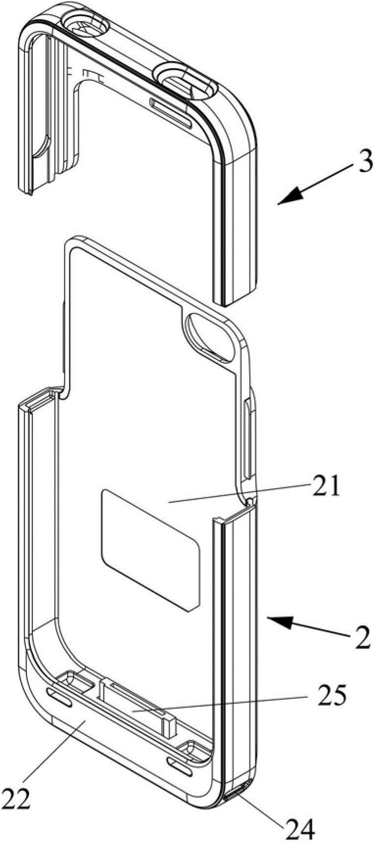
A mobile phone back clip with charging function, the back clip includes: a body and an upper cover. A lithium polymer rechargeable battery is built in the body; a base connector is provided on the inner side of the bottom frame of the body to cooperate with the rechargeable battery; a charging button and a charging button are arranged on the outside of the bottom frame of the body. Charging indicator light; one end of the bottom frame of the body is provided with a charging switch, and the other end is provided with a USB data line interface for charging; the utility model is convenient for users to charge the mobile phone outdoors and improves the use time of the mobile phone .
Description
Claims (4)
Priority Applications (1)
| Application Number | Priority Date | Filing Date | Title |
|---|---|---|---|
| CN2012202190435U CN202424807U (en) | 2012-05-16 | 2012-05-16 | Mobile phone back clip with charging function |
Applications Claiming Priority (1)
| Application Number | Priority Date | Filing Date | Title |
|---|---|---|---|
| CN2012202190435U CN202424807U (en) | 2012-05-16 | 2012-05-16 | Mobile phone back clip with charging function |
Publications (1)
| Publication Number | Publication Date |
|---|---|
| CN202424807U true CN202424807U (en) | 2012-09-05 |
Family
ID=46749528
Family Applications (1)
| Application Number | Title | Priority Date | Filing Date |
|---|---|---|---|
| CN2012202190435U Expired - Fee Related CN202424807U (en) | 2012-05-16 | 2012-05-16 | Mobile phone back clip with charging function |
Country Status (1)
| Country | Link |
|---|---|
| CN (1) | CN202424807U (en) |
Cited By (12)
| Publication number | Priority date | Publication date | Assignee | Title |
|---|---|---|---|---|
| WO2014131237A1 (en) * | 2013-02-28 | 2014-09-04 | Jiang Hongjun | Side-slipping/side-standing rotatable back-clamp battery structure |
| CN105187570A (en) * | 2015-03-12 | 2015-12-23 | 广州登宇电子科技有限公司 | Portable and chargeable mobile phone sleeve |
| USD781277S1 (en) | 2015-01-27 | 2017-03-14 | TJ Cameron | Mobile phone case |
| US9628707B2 (en) | 2014-12-23 | 2017-04-18 | PogoTec, Inc. | Wireless camera systems and methods |
| US9635222B2 (en) | 2014-08-03 | 2017-04-25 | PogoTec, Inc. | Wearable camera systems and apparatus for aligning an eyewear camera |
| US9823494B2 (en) | 2014-08-03 | 2017-11-21 | PogoTec, Inc. | Wearable camera systems and apparatus and method for attaching camera systems or other electronic devices to wearable articles |
| US10241351B2 (en) | 2015-06-10 | 2019-03-26 | PogoTec, Inc. | Eyewear with magnetic track for electronic wearable device |
| US10341787B2 (en) | 2015-10-29 | 2019-07-02 | PogoTec, Inc. | Hearing aid adapted for wireless power reception |
| US10481417B2 (en) | 2015-06-10 | 2019-11-19 | PogoTec, Inc. | Magnetic attachment mechanism for electronic wearable device |
| US10863060B2 (en) | 2016-11-08 | 2020-12-08 | PogoTec, Inc. | Smart case for electronic wearable device |
| US11300857B2 (en) | 2018-11-13 | 2022-04-12 | Opkix, Inc. | Wearable mounts for portable camera |
| US11558538B2 (en) | 2016-03-18 | 2023-01-17 | Opkix, Inc. | Portable camera system |
-
2012
- 2012-05-16 CN CN2012202190435U patent/CN202424807U/en not_active Expired - Fee Related
Cited By (18)
| Publication number | Priority date | Publication date | Assignee | Title |
|---|---|---|---|---|
| WO2014131237A1 (en) * | 2013-02-28 | 2014-09-04 | Jiang Hongjun | Side-slipping/side-standing rotatable back-clamp battery structure |
| US10620459B2 (en) | 2014-08-03 | 2020-04-14 | PogoTec, Inc. | Wearable camera systems and apparatus and method for attaching camera systems or other electronic devices to wearable articles |
| US9823494B2 (en) | 2014-08-03 | 2017-11-21 | PogoTec, Inc. | Wearable camera systems and apparatus and method for attaching camera systems or other electronic devices to wearable articles |
| US10185163B2 (en) | 2014-08-03 | 2019-01-22 | PogoTec, Inc. | Wearable camera systems and apparatus and method for attaching camera systems or other electronic devices to wearable articles |
| US9635222B2 (en) | 2014-08-03 | 2017-04-25 | PogoTec, Inc. | Wearable camera systems and apparatus for aligning an eyewear camera |
| US10348965B2 (en) | 2014-12-23 | 2019-07-09 | PogoTec, Inc. | Wearable camera system |
| US9930257B2 (en) | 2014-12-23 | 2018-03-27 | PogoTec, Inc. | Wearable camera system |
| US9628707B2 (en) | 2014-12-23 | 2017-04-18 | PogoTec, Inc. | Wireless camera systems and methods |
| US10887516B2 (en) | 2014-12-23 | 2021-01-05 | PogoTec, Inc. | Wearable camera system |
| USD781277S1 (en) | 2015-01-27 | 2017-03-14 | TJ Cameron | Mobile phone case |
| CN105187570A (en) * | 2015-03-12 | 2015-12-23 | 广州登宇电子科技有限公司 | Portable and chargeable mobile phone sleeve |
| US10241351B2 (en) | 2015-06-10 | 2019-03-26 | PogoTec, Inc. | Eyewear with magnetic track for electronic wearable device |
| US10481417B2 (en) | 2015-06-10 | 2019-11-19 | PogoTec, Inc. | Magnetic attachment mechanism for electronic wearable device |
| US10341787B2 (en) | 2015-10-29 | 2019-07-02 | PogoTec, Inc. | Hearing aid adapted for wireless power reception |
| US11166112B2 (en) | 2015-10-29 | 2021-11-02 | PogoTec, Inc. | Hearing aid adapted for wireless power reception |
| US11558538B2 (en) | 2016-03-18 | 2023-01-17 | Opkix, Inc. | Portable camera system |
| US10863060B2 (en) | 2016-11-08 | 2020-12-08 | PogoTec, Inc. | Smart case for electronic wearable device |
| US11300857B2 (en) | 2018-11-13 | 2022-04-12 | Opkix, Inc. | Wearable mounts for portable camera |
Similar Documents
| Publication | Publication Date | Title |
|---|---|---|
| CN202424807U (en) | Mobile phone back clip with charging function | |
| CN202635911U (en) | Split type mobile phone protective sleeve | |
| CN202407553U (en) | Mobile phone charging protective sleeve | |
| CN202424276U (en) | Mobile cell phone power supply with external keys | |
| CN202636015U (en) | Split type mobile phone back clamp | |
| CN202651825U (en) | A portable charger | |
| CN103916500A (en) | Portable IPHONE4 Stand with Power Bank | |
| CN202407554U (en) | Mobile phone protecting cover provided with bar code reader | |
| CN201887806U (en) | Charging protective sleeve for iPhone | |
| CN201226514Y (en) | Portable mobile power supply for mobile phone | |
| CN202121636U (en) | Handset housing with charging battery | |
| CN204633421U (en) | Portable power source | |
| CN102932507A (en) | Rechargeable mobile phone protection shell | |
| CN204992676U (en) | Portable phone box that charges | |
| CN204993527U (en) | Cell phone stand with function of charging | |
| CN205624954U (en) | Multi -functional moving arm area | |
| CN211702128U (en) | Solar mobile phone shell | |
| CN202154176U (en) | Waist bag | |
| CN204932831U (en) | Portable dancing device | |
| CN212187782U (en) | Plush toy with portable power source function | |
| CN205389223U (en) | Cell -phone frame with alarm function | |
| CN204316149U (en) | A kind of back splint battery to charging of mobile devices and protection | |
| CN204271686U (en) | A kind of Wrist belt-type charger | |
| CN204304493U (en) | A kind of portable charger for handset | |
| CN204809916U (en) | Hand formula cell -phone charger |
Legal Events
| Date | Code | Title | Description |
|---|---|---|---|
| C14 | Grant of patent or utility model | ||
| GR01 | Patent grant | ||
| CF01 | Termination of patent right due to non-payment of annual fee | ||
| CF01 | Termination of patent right due to non-payment of annual fee |
Granted publication date: 20120905 Termination date: 20160516 |