CN202133955U - a sensory ring - Google Patents
a sensory ring Download PDFInfo
- Publication number
- CN202133955U CN202133955U CN201120218066U CN201120218066U CN202133955U CN 202133955 U CN202133955 U CN 202133955U CN 201120218066 U CN201120218066 U CN 201120218066U CN 201120218066 U CN201120218066 U CN 201120218066U CN 202133955 U CN202133955 U CN 202133955U
- Authority
- CN
- China
- Prior art keywords
- finger ring
- module
- body sense
- ring
- processing module
- Prior art date
- Legal status (The legal status is an assumption and is not a legal conclusion. Google has not performed a legal analysis and makes no representation as to the accuracy of the status listed.)
- Expired - Lifetime
Links
- 230000001953 sensory effect Effects 0.000 title 1
- 230000006698 induction Effects 0.000 claims description 11
- 230000001133 acceleration Effects 0.000 claims description 4
- 230000010365 information processing Effects 0.000 abstract description 6
- 230000003238 somatosensory effect Effects 0.000 abstract 8
- 238000010586 diagram Methods 0.000 description 4
- 230000007812 deficiency Effects 0.000 description 1
- 230000004048 modification Effects 0.000 description 1
- 238000012986 modification Methods 0.000 description 1
- 238000012797 qualification Methods 0.000 description 1
Images


Landscapes
- Telephone Function (AREA)
- Mobile Radio Communication Systems (AREA)
Abstract
一种体感指环,包括指环本体、体感装置,以及用于安装所述体感装置的内部空间,其中所述体感装置进一步还包括:体感采集模块、信息处理模块和无线收发模块,所述体感采集模块,连接所述信息处理模块,用于采集指环的运动轨迹;所述信息处理模块,分别连接所述体感采集模块和所述无线收发模块,用于将指环的运动轨迹换算成空中轨迹,并将其传送给所述无线收发模块;所述无线收发模块,连接所述信息处理模块,用于将所述的指环空中轨迹发送给移动终端。本实用新型的体感指环,在不用拿出移动终端作任何操作的情况下,用户就可以利用指环的空中轨迹操作移动终端。
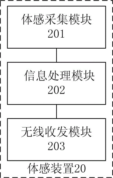
A somatosensory ring, comprising a ring body, a somatosensory device, and an internal space for installing the somatosensory device, wherein the somatosensory device further includes: a somatosensory collection module, an information processing module, and a wireless transceiver module, and the somatosensory collection module , connected to the information processing module, for collecting the motion trajectory of the ring; the information processing module, respectively connected to the somatosensory collection module and the wireless transceiver module, for converting the motion trajectory of the ring into an air trajectory, and It is sent to the wireless transceiver module; the wireless transceiver module is connected to the information processing module and is used to send the air trajectory of the ring to the mobile terminal. With the somatosensory finger ring of the utility model, the user can operate the mobile terminal by using the track in the air of the ring without taking out the mobile terminal for any operation.
Description
Claims (4)
Priority Applications (1)
| Application Number | Priority Date | Filing Date | Title |
|---|---|---|---|
| CN201120218066U CN202133955U (en) | 2011-06-25 | 2011-06-25 | a sensory ring |
Applications Claiming Priority (1)
| Application Number | Priority Date | Filing Date | Title |
|---|---|---|---|
| CN201120218066U CN202133955U (en) | 2011-06-25 | 2011-06-25 | a sensory ring |
Publications (1)
| Publication Number | Publication Date |
|---|---|
| CN202133955U true CN202133955U (en) | 2012-02-01 |
Family
ID=45522718
Family Applications (1)
| Application Number | Title | Priority Date | Filing Date |
|---|---|---|---|
| CN201120218066U Expired - Lifetime CN202133955U (en) | 2011-06-25 | 2011-06-25 | a sensory ring |
Country Status (1)
| Country | Link |
|---|---|
| CN (1) | CN202133955U (en) |
Cited By (6)
| Publication number | Priority date | Publication date | Assignee | Title |
|---|---|---|---|---|
| CN104038800A (en) * | 2014-05-21 | 2014-09-10 | 常璨 | Finger ring for smart television input and input method of finger ring |
| CN104200555A (en) * | 2014-09-12 | 2014-12-10 | 四川农业大学 | Method and device for finger ring gesture door opening |
| CN104935721A (en) * | 2014-03-20 | 2015-09-23 | 宇龙计算机通信科技(深圳)有限公司 | A method and device for interacting with an intelligent terminal |
| CN106293138A (en) * | 2016-08-12 | 2017-01-04 | 包爱民 | A kind of body sensing ring mouse |
| TWI684117B (en) * | 2018-03-23 | 2020-02-01 | 大陸商雲穀(固安)科技有限公司 | Gesture post remote control operation method and gesture post remote control device |
| US12013725B2 (en) | 2013-11-29 | 2024-06-18 | Ouraring, Inc. | Wearable computing device |
-
2011
- 2011-06-25 CN CN201120218066U patent/CN202133955U/en not_active Expired - Lifetime
Cited By (44)
| Publication number | Priority date | Publication date | Assignee | Title |
|---|---|---|---|---|
| US12429910B2 (en) | 2013-11-29 | 2025-09-30 | Ouraring Inc. | Wearable computing device |
| US12449846B2 (en) | 2013-11-29 | 2025-10-21 | Ouraring Inc. | Wearable computing device |
| US12530050B2 (en) | 2013-11-29 | 2026-01-20 | Ouraring Inc. | Wearable computing device |
| US12498756B2 (en) | 2013-11-29 | 2025-12-16 | Ouraring Inc. | Wearable computing device |
| US12493321B2 (en) | 2013-11-29 | 2025-12-09 | Ouraring Inc. | Wearable computing device |
| US12468342B2 (en) | 2013-11-29 | 2025-11-11 | Ouraring Inc. | Wearable computing device |
| US12461561B2 (en) | 2013-11-29 | 2025-11-04 | Ouraring Inc. | Wearable computing device |
| US12013725B2 (en) | 2013-11-29 | 2024-06-18 | Ouraring, Inc. | Wearable computing device |
| US12210381B2 (en) | 2013-11-29 | 2025-01-28 | Ouraring, Inc. | Wearable computing device |
| US12222759B2 (en) | 2013-11-29 | 2025-02-11 | Ouraring, Inc. | Wearable computing device |
| US12222758B2 (en) | 2013-11-29 | 2025-02-11 | Ouraring, Inc. | Wearable computing device |
| US12228968B2 (en) | 2013-11-29 | 2025-02-18 | Ouraring, Inc. | Wearable computing device |
| US12235679B2 (en) | 2013-11-29 | 2025-02-25 | Ouraring, Inc. | Wearable computing device |
| US12332689B1 (en) | 2013-11-29 | 2025-06-17 | Ouraring Inc. | Wearable computing device |
| US12332688B2 (en) | 2013-11-29 | 2025-06-17 | Ouraring, Inc. | Wearable computing device |
| US12346160B2 (en) | 2013-11-29 | 2025-07-01 | Ouraring, Inc. | Wearable computing device |
| US12393229B2 (en) | 2013-11-29 | 2025-08-19 | Ouraring Inc. | Wearable computing device |
| US12393228B2 (en) | 2013-11-29 | 2025-08-19 | Ouraring Inc. | Wearable computing device |
| US12393227B2 (en) | 2013-11-29 | 2025-08-19 | Ouraring, Inc. | Wearable computing device |
| US12399531B2 (en) | 2013-11-29 | 2025-08-26 | Ouraring Inc. | Wearable computing device |
| US12461560B2 (en) | 2013-11-29 | 2025-11-04 | Ouraring Inc. | Wearable computing device |
| US12449843B2 (en) | 2013-11-29 | 2025-10-21 | Ouraring Inc. | Wearable computing device |
| US12422889B2 (en) | 2013-11-29 | 2025-09-23 | Ouraring Inc. | Wearable computing device |
| US12429909B2 (en) | 2013-11-29 | 2025-09-30 | Ouraring Inc. | Wearable computing device |
| US12429911B2 (en) | 2013-11-29 | 2025-09-30 | Ouraring Inc. | Wearable computing device |
| US12429908B2 (en) | 2013-11-29 | 2025-09-30 | Ouraring Inc. | Wearable computing device |
| US12436566B2 (en) | 2013-11-29 | 2025-10-07 | Ouraring Inc. | Wearable computing device |
| US12443228B2 (en) | 2013-11-29 | 2025-10-14 | Ouraring Inc. | Wearable computing device |
| US12443231B2 (en) | 2013-11-29 | 2025-10-14 | Ouraring Inc. | Wearable computing device |
| US12443229B2 (en) | 2013-11-29 | 2025-10-14 | Ouraring Inc. | Wearable computing device |
| US12443230B2 (en) | 2013-11-29 | 2025-10-14 | Ouraring Inc. | Wearable computing device |
| US12399530B2 (en) | 2013-11-29 | 2025-08-26 | Ouraring Inc. | Wearable computing device |
| US12449844B2 (en) | 2013-11-29 | 2025-10-21 | Ouraring Inc. | Wearable computing device |
| US12449848B2 (en) | 2013-11-29 | 2025-10-21 | Ouraring Inc. | Wearable computing device |
| US12449847B2 (en) | 2013-11-29 | 2025-10-21 | Ouraring Inc. | Wearable computing device |
| US12449845B2 (en) | 2013-11-29 | 2025-10-21 | Ouraring Inc. | Wearable computing device |
| US12449849B2 (en) | 2013-11-29 | 2025-10-21 | Ouraring Inc. | Wearable computing device |
| CN104935721B (en) * | 2014-03-20 | 2018-02-13 | 宇龙计算机通信科技(深圳)有限公司 | A kind of method and device interactive with intelligent terminal |
| CN104935721A (en) * | 2014-03-20 | 2015-09-23 | 宇龙计算机通信科技(深圳)有限公司 | A method and device for interacting with an intelligent terminal |
| CN104038800A (en) * | 2014-05-21 | 2014-09-10 | 常璨 | Finger ring for smart television input and input method of finger ring |
| CN104200555A (en) * | 2014-09-12 | 2014-12-10 | 四川农业大学 | Method and device for finger ring gesture door opening |
| CN106293138A (en) * | 2016-08-12 | 2017-01-04 | 包爱民 | A kind of body sensing ring mouse |
| US10880463B2 (en) | 2018-03-23 | 2020-12-29 | Yungu (Gu'an) Technology Co., Ltd. | Remote control operation method for gesture post and gesture post remote control device |
| TWI684117B (en) * | 2018-03-23 | 2020-02-01 | 大陸商雲穀(固安)科技有限公司 | Gesture post remote control operation method and gesture post remote control device |
Similar Documents
| Publication | Publication Date | Title |
|---|---|---|
| CN202133955U (en) | a sensory ring | |
| CN110286865A (en) | A kind of display methods and electronic equipment of touch screen | |
| CN109891860A (en) | The method of the connection terminal of electronic equipment and electronic equipment identification external equipment | |
| KR20170136258A (en) | Foldable electronic device | |
| KR20150105064A (en) | Cover member, electronic device and method for wireless charging | |
| CN103263094A (en) | Intelligent induction glove system | |
| CN103558750B (en) | The method of intelligent watch and transmission electronic business card | |
| CN105933204B (en) | Method and apparatus for sending synchronization message from first device to second device | |
| CN204206211U (en) | A portable 3G/4G wireless router | |
| CN110020386B (en) | Application page sharing method, mobile terminal and computer readable storage medium | |
| CN105871425B (en) | The method and apparatus that first equipment receives synchronization message from the second equipment | |
| CN110267125A (en) | Intelligent meter reading method and related products | |
| KR20160031196A (en) | Method for controlling display in electronic device and the electronic device | |
| CN109193975A (en) | A kind of wireless charging device and terminal | |
| US9830001B2 (en) | Method, device and system for collecting writing pattern using ban | |
| CN110165756A (en) | A kind of wireless charging method and terminal device | |
| CN110191477A (en) | A kind of web search control method, terminal and computer readable storage medium | |
| CN109445660A (en) | A kind of wearable device control method, mobile terminal and wearable device | |
| CN210015334U (en) | Wearable device | |
| CN108829337A (en) | Apparatus control method, device and computer readable storage medium | |
| JP6779707B2 (en) | Electronics, control methods, and control programs | |
| CN103968849A (en) | A vehicle navigation method using an intelligent mobile phone sensor | |
| CN206450230U (en) | A kind of pedestrian track estimation device | |
| CN206077638U (en) | A kind of electronic communication equipment | |
| JP3189431U (en) | Projection keyboard for portable communication devices |
Legal Events
| Date | Code | Title | Description |
|---|---|---|---|
| C14 | Grant of patent or utility model | ||
| GR01 | Patent grant | ||
| ASS | Succession or assignment of patent right |
Owner name: BEIJING BORQS SOFTWARE TECHNOLOGY CO., LTD. Effective date: 20120320 Owner name: BORQS COMMUNICATION TECHNOLOGY (BEIJING) CO., LTD. Free format text: FORMER OWNER: BEIJING BORQS SOFTWARE TECHNOLOGY CO., LTD. Effective date: 20120320 |
|
| C41 | Transfer of patent application or patent right or utility model | ||
| TR01 | Transfer of patent right |
Effective date of registration: 20120320 Address after: 100102 D building, building 9, South Central Road, Chaoyang District, Wangjing, Beijing, Wangjing Co-patentee after: Beijing Borqs Software Technology Co., Ltd. Patentee after: Borqs Beijing Ltd. Address before: 100102 D building, building 9, South Central Road, Chaoyang District, Wangjing, Beijing, Wangjing Patentee before: Beijing Borqs Software Technology Co., Ltd. |
|
| CX01 | Expiry of patent term | ||
| CX01 | Expiry of patent term |
Granted publication date: 20120201 |