CN201946736U - A microwave communication parabolic antenna hanger - Google Patents
A microwave communication parabolic antenna hanger Download PDFInfo
- Publication number
- CN201946736U CN201946736U CN2010206368921U CN201020636892U CN201946736U CN 201946736 U CN201946736 U CN 201946736U CN 2010206368921 U CN2010206368921 U CN 2010206368921U CN 201020636892 U CN201020636892 U CN 201020636892U CN 201946736 U CN201946736 U CN 201946736U
- Authority
- CN
- China
- Prior art keywords
- frame
- fine
- horizontal
- parabolic antenna
- tuning screw
- Prior art date
- Legal status (The legal status is an assumption and is not a legal conclusion. Google has not performed a legal analysis and makes no representation as to the accuracy of the status listed.)
- Expired - Lifetime
Links
- 238000004891 communication Methods 0.000 title claims abstract description 19
- 229910000831 Steel Inorganic materials 0.000 claims description 6
- 239000010959 steel Substances 0.000 claims description 6
- 230000003014 reinforcing effect Effects 0.000 claims description 4
- 238000010586 diagram Methods 0.000 description 12
- 238000000034 method Methods 0.000 description 7
- 238000009434 installation Methods 0.000 description 3
- 239000002184 metal Substances 0.000 description 3
- 230000005540 biological transmission Effects 0.000 description 2
- 238000013461 design Methods 0.000 description 2
- 230000035945 sensitivity Effects 0.000 description 2
- CWYNVVGOOAEACU-UHFFFAOYSA-N Fe2+ Chemical compound [Fe+2] CWYNVVGOOAEACU-UHFFFAOYSA-N 0.000 description 1
- 230000009286 beneficial effect Effects 0.000 description 1
- 230000000694 effects Effects 0.000 description 1
- 239000000463 material Substances 0.000 description 1
- 239000007769 metal material Substances 0.000 description 1
- 238000010295 mobile communication Methods 0.000 description 1
- 238000012986 modification Methods 0.000 description 1
- 230000004048 modification Effects 0.000 description 1
- 238000012805 post-processing Methods 0.000 description 1
- 238000000844 transformation Methods 0.000 description 1
- 230000009466 transformation Effects 0.000 description 1
Images


Landscapes
- Aerials With Secondary Devices (AREA)
Abstract
Description
技术领域technical field
本实用新型涉及微波天线的配套设备领域,尤其是涉及一种微波通信抛物面天线挂架。The utility model relates to the field of matching equipment for microwave antennas, in particular to a microwave communication parabolic antenna hanger.
背景技术Background technique
微波通信是目前国际上常用的无线通信手段之一,它被广泛用于数据传输、广播电视传送、移动通信基站信号联落等领域。随着通信频段的不断提高,天线口径越来越小。传统中的天线挂架被应用于小型口径天线上,其主要材料为黑色金属,但是传统中的挂架存有以下缺点:一是由于设计方式的关系,使得传统的挂架在进行天线调测时,灵敏度不够高,这样不利于上站人员工作;二是传统天线挂架的稳定性不够好,常常存在安全隐患;三是黑色金属材料比重较大,挂架本身很重,与轻巧的天线不相匹配,且使用黑色金属后处理出来的挂架表面粗糙不光滑,与漂亮的天线外观不协调。Microwave communication is one of the commonly used wireless communication means in the world at present. It is widely used in data transmission, radio and television transmission, mobile communication base station signal connection and other fields. With the continuous improvement of the communication frequency band, the antenna diameter is getting smaller and smaller. The traditional antenna hanger is applied to the small-caliber antenna, and its main material is black metal, but the traditional hanger has the following disadvantages: First, due to the relationship between the design method, the traditional hanger is used for antenna commissioning. The sensitivity is not high enough, which is not conducive to the work of the station personnel; the second is that the stability of the traditional antenna hanger is not good enough, and there are often potential safety hazards; the third is that the ferrous metal material has a large proportion, and the hanger itself is very heavy. Mismatched, and the surface of the hanger made of black metal post-processing is rough and not smooth, which does not match the beautiful appearance of the antenna.
发明内容Contents of the invention
针对上述问题,本实用新型的目的在于通过提供一种调节灵敏度高、自重较轻且外观美观的天线挂架。In view of the above problems, the purpose of this utility model is to provide an antenna hanger with high adjustment sensitivity, light weight and beautiful appearance.
本实用新型为解决其技术问题所采用的技术方案是:The technical scheme that the utility model adopts for solving its technical problem is:
一种微波通信抛物面天线挂架,其特征在于包括:夹码架、水平架、俯仰架、固定夹码、水平微调螺杆和垂直微调螺杆,所述夹码架与固定夹码相连,两者之间形成一夹紧空间,所述夹码架与水平架相连,并通过水平微调螺杆实现水平微调,所述水平架与俯仰架相连,并通过垂直微调螺杆实现垂直微调。A microwave communication parabolic antenna hanger is characterized in that it includes: a clamping frame, a horizontal frame, a pitch frame, a fixed clamping frame, a horizontal fine-tuning screw and a vertical fine-tuning screw, the clamping frame is connected with the fixed clamping frame, and the A clamping space is formed between them, the clamping frame is connected with the horizontal frame, and the horizontal fine adjustment is realized through the horizontal fine adjustment screw rod, and the horizontal frame is connected with the pitch frame, and the vertical fine adjustment is realized through the vertical fine adjustment screw rod.
作为上述方案的进一步改进,所述夹码架和俯仰架的侧壁上均设有月牙孔和螺栓过孔,并通过螺栓与所述水平架相连接。As a further improvement of the above solution, crescent holes and bolt passing holes are provided on the side walls of the clamping frame and the pitching frame, and are connected to the horizontal frame by bolts.
进一步,所述挂架通过水平微调螺杆实现水平-15°~+15°微调,通过垂直微调螺杆实现垂直-25°~+25°微调。Further, the hanger realizes horizontal -15°~+15° fine adjustment through the horizontal fine adjustment screw, and vertical -25°~+25° fine adjustment through the vertical fine adjustment screw.
进一步,所述夹码架为一V型半封闭盒体,其V面设计有防滑齿,边沿上设有供微调螺杆穿过的过孔。Further, the clamping frame is a V-shaped semi-closed box, the V surface is designed with anti-slip teeth, and the edge is provided with a through hole for the fine-tuning screw to pass through.
进一步,所述水平架为呈山形状的半封闭盒体,其边沿上设有供微调螺杆穿过的过孔。Furthermore, the horizontal frame is a semi-enclosed box in the shape of a mountain, and a through hole for the fine-tuning screw to pass is provided on its edge.
进一步,所述俯仰架为L型结构,其中一个面上设有螺栓过孔,通过螺栓与外部抛物面天线相连接,另一个面的边沿上设有供微调螺杆穿过的过孔。Further, the pitching frame is an L-shaped structure, one of which is provided with bolt holes for connecting with the external parabolic antenna, and the edge of the other surface is provided with holes for fine-tuning screws to pass through.
进一步,所述俯仰架的底面设有相互垂直交错的加强筋。Further, the bottom surface of the pitching frame is provided with reinforcing ribs that intersect vertically with each other.
进一步,所述水平微调螺杆和垂直微调螺杆的连接头为圆球形结构Further, the connecting head of the horizontal fine-tuning screw and the vertical fine-tuning screw is a spherical structure
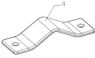
进一步,所述固定夹码为V型结构的条状体。Further, the fixed clip is a strip with a V-shaped structure.
此外,所述夹码架与固定夹码通过固定螺栓进行连接,两者形成的空间内可容纳直径50mm~120mm的钢管或角钢。In addition, the clip frame and the fixed clip are connected by fixing bolts, and the space formed by the two can accommodate steel pipes or angle steels with a diameter of 50 mm to 120 mm.
本实用新型的有益效果是:第一,易于调节,微调效果尤为突出,本实用新型通过水平微调螺杆和垂直微调螺杆对天线挂架进行微调,以满足不同条件下的需要,具有很好的使用价值;第二,本实用新型的各个组成部件上,分别设有V型结构、加强筋以及防滑齿,使得产品稳定性增加,安全性能好;此外,自重轻、外观美观,本实用新型摒弃了传统使用黑色金属的方式,以组合结构和轻质零部件代替,使得产品本身自重减轻,外观美观。The beneficial effects of the utility model are: first, it is easy to adjust, and the fine-tuning effect is particularly outstanding. The utility model fine-tunes the antenna hanger through the horizontal fine-tuning screw and the vertical fine-tuning screw to meet the needs under different conditions, and has a good use value; second, each component of the utility model is provided with a V-shaped structure, reinforcing ribs and anti-skid teeth, so that the product stability is increased and the safety performance is good; in addition, the utility model has light weight and beautiful appearance. The traditional method of using black metal is replaced by combined structure and lightweight components, which reduces the weight of the product itself and has a beautiful appearance.
附图说明Description of drawings
下面结合附图和具体实施例对本实用新型做进一步说明:Below in conjunction with accompanying drawing and specific embodiment the utility model is described further:
图1是本实用新型组合结构示意图;Fig. 1 is a schematic diagram of the combined structure of the utility model;
图2是本实用新型夹码架结构示意图;Fig. 2 is a structural schematic diagram of the clipping frame of the present utility model;
图3是本实用新型水平架结构示意图;Fig. 3 is a structural schematic diagram of the utility model horizontal frame;
图4是本实用新型俯仰架结构示意图;Fig. 4 is a structural schematic diagram of the pitch frame of the utility model;
图5是本实用新型水平微调螺杆结构示意图;Fig. 5 is a schematic diagram of the horizontal fine-tuning screw structure of the utility model;
图6是本实用新型固定夹码结构示意图;Fig. 6 is a schematic diagram of the structure of the fixed clip of the utility model;
图7是本实用新型夹码架与水平架连接结构示意图;Fig. 7 is a schematic diagram of the connection structure between the clamping frame and the horizontal frame of the utility model;
图8是本实用新型水平架与俯仰架结构示意图;Fig. 8 is a structural schematic diagram of the horizontal frame and the pitching frame of the utility model;
图9是本实用新型水平微调螺杆连接示意图;Fig. 9 is a schematic diagram of the horizontal fine-tuning screw connection of the utility model;
图10是本实用新型垂直微调螺杆连接示意图;Fig. 10 is a schematic diagram of the connection of the vertical fine-tuning screw of the utility model;
图11是本实用新型在0.3m或0.6m微波抛物面天线上的应用结构示意图。Fig. 11 is a schematic diagram of the application structure of the utility model on a 0.3m or 0.6m microwave parabolic antenna.
具体实施方式Detailed ways
参照图1-图8,一种微波通信抛物面天线挂架,其特征在于包括:夹码架1、水平架2、俯仰架3、固定夹码4、水平微调螺杆5和垂直微调螺杆6,所述夹码架1与固定夹码4相连,两者之间形成一夹紧空间,所述夹码架1与水平架2相连,并通过水平微调螺杆5实现水平微调,所述水平架2与俯仰架3相连,并通过垂直微调螺杆6实现垂直微调。Referring to Fig. 1-Fig. 8, a parabolic antenna hanger for microwave communication is characterized in that it comprises:
作为本实用新型优选的实施方案,所述夹码架1和俯仰架3的侧壁上均设有月牙孔7和螺栓过孔8,并通过螺栓与所述水平架2相连接。As a preferred embodiment of the present invention,
所述挂架通过水平微调螺杆5实现水平-15°~+15°微调,通过垂直微调螺杆6实现垂直-25°~+25°微调。The hanger is fine-tuned horizontally from -15° to +15° through the horizontal fine-tuning
所述夹码架1为一V型半封闭盒体,其V面设计有防滑齿11,边沿上设有供微调螺杆穿过的过孔9。The
所述水平架2为呈山形状的半封闭盒体,其边沿上设有供微调螺杆穿过的过孔9。The
所述俯仰架3为L型结构,其中一个面上设有螺栓过孔,通过螺栓与外部抛物面天线相连接,另一个面的边沿上设有供微调螺杆穿过的过孔9。The
所述俯仰架3的底面设有相互垂直交错的加强筋31。The bottom surface of the
所述水平微调螺杆5和垂直微调螺杆6的连接头10为圆球形结构。The connecting
所述固定夹码4为V型结构的条状体。The
所述夹码架1与固定夹码4通过固定螺栓进行连接,两者形成的空间内可容纳直径50mm~120mm的钢管或角钢。The
如图1-图10所示,夹码架1与水平架2的连接固定方式,是由两个固定螺栓通过夹码架1前后两侧面的一对螺栓过孔8和一对30°月牙孔7与水平架2前后两侧面的两对螺栓过孔8相互连接固定的。水平架2的一面还设有螺纹孔,连接时螺栓过孔8和螺纹孔相对应,30°月牙孔与螺纹孔相对应。同时可通过水平微调螺杆5进行水平调节定位。As shown in Figures 1-10, the connection and fixation method between the
水平微调螺杆5的安装方法是先把定位螺母602放入夹码架1一侧凸起的螺母固定结构603中,然后把水平微调螺杆5旋转穿过夹码架1一侧凸起的螺栓过孔9和定位螺母602,再把水平微调螺杆5头部的球头部分10装入水平架2一侧凸起的水平微调螺杆5卡槽结构600中,并用紧固螺丝601挡在水平微调螺杆5头部的球头一侧进行锁紧。The installation method of the horizontal fine-
水平架1与俯仰架3的连接固定方式,是由四个固定螺栓通过俯仰架3其中一面上的一个螺栓过孔和三个50°月牙孔与水平架顶面的四个螺纹连接孔,相互连接固定的,同时可通过垂直微调螺杆6进行俯仰调节定位。The connection and fixing method between the
垂直微调螺杆6的安装方法是先把定位螺母802放入水平架2顶部凸起的螺母固定结构803中,然后把垂直微调螺杆6旋转穿过水平架2顶部凸起的螺栓过孔9和定位螺母802,再把垂直微调螺杆6头部的球头部分10装入俯仰架3顶部凸起的垂直微调螺杆6卡槽结构800中,并用紧固螺丝801挡在垂直微调螺杆6头部的球头10的一侧进行锁紧。The installation method of the vertical fine-
上述中提到的螺栓过孔9实际上就是螺栓过孔,这里将它与螺栓过孔相区别,主要是因为在进行水平微调和垂直微调时,所述铰轴9起到旋转轴的作用,比如在进行水平微调时,夹码架1会以螺栓过孔8中穿过的螺栓为中心进行旋转,相应地,调整角度由月牙孔两端的开孔大小范围来决定。The bolt through
对于整体挂架的最终安装固定,是由四个固定螺栓穿过夹码架底部的四个螺栓过孔,用夹码以及螺母将其锁紧固定在抱杆上面。For the final installation and fixation of the overall hanger, four fixing bolts pass through the four bolt holes at the bottom of the clip frame, and are locked and fixed on the pole with clips and nuts.
图11是将本实用新型所述的挂架与抛物面反射面共同组合而成的微波通信抛物面天线的整体结构示意图。Fig. 11 is a schematic diagram of the overall structure of a microwave communication parabolic antenna formed by combining the pylon and the parabolic reflecting surface of the present invention.
综上所述,本实用新型设计合理巧妙、性能可靠、组装方便,因此应用前景广阔。To sum up, the utility model has reasonable and ingenious design, reliable performance, and convenient assembly, so it has broad application prospects.
以上对本实用新型的较佳实施进行了具体说明,当然,本实用新型还可以采用与上述实施方式不同的形式,熟悉本领域的技术人员在不违背本发明精神的前提下所作的等同的变换或相应的改动,都应该属于本实用新型的保护范围内。The preferred implementation of the present utility model has been specifically described above. Of course, the present utility model can also adopt forms different from the above-mentioned embodiments, and those skilled in the art can make equivalent transformations or modifications without violating the spirit of the present invention. Corresponding changes should all belong to the protection scope of the present utility model.
Claims (10)
Priority Applications (1)
| Application Number | Priority Date | Filing Date | Title |
|---|---|---|---|
| CN2010206368921U CN201946736U (en) | 2010-11-22 | 2010-11-22 | A microwave communication parabolic antenna hanger |
Applications Claiming Priority (1)
| Application Number | Priority Date | Filing Date | Title |
|---|---|---|---|
| CN2010206368921U CN201946736U (en) | 2010-11-22 | 2010-11-22 | A microwave communication parabolic antenna hanger |
Publications (1)
| Publication Number | Publication Date |
|---|---|
| CN201946736U true CN201946736U (en) | 2011-08-24 |
Family
ID=44474072
Family Applications (1)
| Application Number | Title | Priority Date | Filing Date |
|---|---|---|---|
| CN2010206368921U Expired - Lifetime CN201946736U (en) | 2010-11-22 | 2010-11-22 | A microwave communication parabolic antenna hanger |
Country Status (1)
| Country | Link |
|---|---|
| CN (1) | CN201946736U (en) |
Cited By (6)
| Publication number | Priority date | Publication date | Assignee | Title |
|---|---|---|---|---|
| CN102439787A (en) * | 2011-09-20 | 2012-05-02 | 华为技术有限公司 | Regulating device of microwave antenna |
| WO2016169271A1 (en) * | 2015-04-21 | 2016-10-27 | 中兴通讯股份有限公司 | Mounting device |
| TWI562452B (en) * | 2014-09-09 | 2016-12-11 | Hon Hai Prec Ind Co Ltd | Hanging bracket |
| CN108023157A (en) * | 2017-12-14 | 2018-05-11 | 广东盛路通信科技股份有限公司 | Parabola antenna communication equipment hanger |
| CN109301438A (en) * | 2018-10-22 | 2019-02-01 | 湖南航天环宇通信科技股份有限公司 | The fine-tuning connecting rod of length and antenna module |
| CN110945715A (en) * | 2017-06-21 | 2020-03-31 | 上海诺基亚贝尔股份有限公司 | Fastening device and related method |
-
2010
- 2010-11-22 CN CN2010206368921U patent/CN201946736U/en not_active Expired - Lifetime
Cited By (12)
| Publication number | Priority date | Publication date | Assignee | Title |
|---|---|---|---|---|
| CN102439787A (en) * | 2011-09-20 | 2012-05-02 | 华为技术有限公司 | Regulating device of microwave antenna |
| WO2012149752A1 (en) * | 2011-09-20 | 2012-11-08 | 华为技术有限公司 | Regulating device for microwave antenna |
| CN102439787B (en) * | 2011-09-20 | 2014-06-04 | 华为技术有限公司 | Regulating device of microwave antenna |
| TWI562452B (en) * | 2014-09-09 | 2016-12-11 | Hon Hai Prec Ind Co Ltd | Hanging bracket |
| WO2016169271A1 (en) * | 2015-04-21 | 2016-10-27 | 中兴通讯股份有限公司 | Mounting device |
| CN110945715A (en) * | 2017-06-21 | 2020-03-31 | 上海诺基亚贝尔股份有限公司 | Fastening device and related method |
| CN110945715B (en) * | 2017-06-21 | 2022-03-01 | 上海诺基亚贝尔股份有限公司 | Fastening device and related method |
| US11631929B2 (en) | 2017-06-21 | 2023-04-18 | Nokia Shanghai Bell Co. Ltd. | Fastening device and associated method |
| CN108023157A (en) * | 2017-12-14 | 2018-05-11 | 广东盛路通信科技股份有限公司 | Parabola antenna communication equipment hanger |
| CN108023157B (en) * | 2017-12-14 | 2023-12-01 | 广东盛路通信科技股份有限公司 | Parabolic antenna communication equipment hanger |
| CN109301438A (en) * | 2018-10-22 | 2019-02-01 | 湖南航天环宇通信科技股份有限公司 | The fine-tuning connecting rod of length and antenna module |
| CN109301438B (en) * | 2018-10-22 | 2023-10-27 | 湖南航天环宇通信科技股份有限公司 | Connecting rod with length capable of being finely adjusted |
Similar Documents
| Publication | Publication Date | Title |
|---|---|---|
| CN201946736U (en) | A microwave communication parabolic antenna hanger | |
| CN204819470U (en) | Regular rack of crane end beam | |
| CN206468028U (en) | A kind of construction anti-falling bracket | |
| CN202672821U (en) | Device for mounting wireless optical communication equipment on single-pipe tower | |
| CN202441193U (en) | General adjustable column of shield door of subway platform | |
| CN208445574U (en) | A kind of portable radio communication device | |
| CN209461911U (en) | A kind of overhead distribution livewire work bracket | |
| CN201261958Y (en) | Cross-arm for cement telephone pole | |
| CN206697592U (en) | Communicate steel tower and its antenna holder | |
| CN221041515U (en) | Medium wave broadcast signal receiving antenna array | |
| CN206191213U (en) | Outdoor RRU installing support | |
| CN219345163U (en) | Double-jack manual plate structure | |
| CN206805925U (en) | A kind of cable identification board support | |
| CN203911232U (en) | Device for fixing grounding bar and N bar of low-voltage power distribution cabinet | |
| CN210838059U (en) | Angle steel tower antenna boom | |
| CN221424770U (en) | Angle-adjustable mounting bracket for street lamp | |
| CN204103865U (en) | A kind of aerial signal amplifying device of wireless routing | |
| CN204843636U (en) | Mounting fixture of plug -type plate body class spare part | |
| CN208039100U (en) | New road science of bridge building safety device | |
| CN206237085U (en) | A kind of composite material cable rack for installing anchor ear | |
| CN220979926U (en) | Cabinet type fan box | |
| CN104681237A (en) | Anti-burglary power transformer mounting bracket | |
| CN208423126U (en) | A kind of positioning antenna assembly | |
| CN204391274U (en) | A kind of terrestrial DTV reception antenna | |
| CN217958067U (en) | A tree support device for municipal greening |
Legal Events
| Date | Code | Title | Description |
|---|---|---|---|
| C14 | Grant of patent or utility model | ||
| GR01 | Patent grant | ||
| CX01 | Expiry of patent term |
Granted publication date: 20110824 |
|
| CX01 | Expiry of patent term |