CN201928419U - Earphone and mobile communication terminal provided with same - Google Patents
Earphone and mobile communication terminal provided with same Download PDFInfo
- Publication number
- CN201928419U CN201928419U CN2011200248901U CN201120024890U CN201928419U CN 201928419 U CN201928419 U CN 201928419U CN 2011200248901 U CN2011200248901 U CN 2011200248901U CN 201120024890 U CN201120024890 U CN 201120024890U CN 201928419 U CN201928419 U CN 201928419U
- Authority
- CN
- China
- Prior art keywords
- earphone
- terminal
- microphone
- channel
- wire
- Prior art date
- Legal status (The legal status is an assumption and is not a legal conclusion. Google has not performed a legal analysis and makes no representation as to the accuracy of the status listed.)
- Expired - Fee Related
Links
Images


Landscapes
- Telephone Function (AREA)
Abstract
Description
技术领域technical field
本实用新型属于耳机技术领域,具体地说,是涉及一种针对具有对讲功能的手机而专门设计的线控耳机以及配置有所述耳机的移动通信终端。The utility model belongs to the technical field of earphones, and in particular relates to a wire-controlled earphone specially designed for a mobile phone with an intercom function and a mobile communication terminal equipped with the earphone.
背景技术Background technique
目前,在应用于移动通信终端的线控耳机中,大多数只能实现接听电话、挂断电话、控制音乐播放、收听调频广播等功能。而随着通信产业的迅速发展以及EVD0技术的日趋成熟,具有Qchat对讲功能的手机应运而生并逐渐受到消费者的青睐。QChat是高通公司推出的基于CDMA 1xEVD0网络的PTT通信技术,也是目前业界公认公网集群中性能最好的技术之一。PTT(Push To Talk),意为“即按即说”,或者俗称“一键通”,具有呼叫建立迅速,方便团队协同使用等优点。基于该项通信技术可以使手机实现目前对讲机的功能。At present, among wire-controlled earphones applied to mobile communication terminals, most of them can only implement functions such as answering calls, hanging up calls, controlling music playback, and listening to FM radio. With the rapid development of the communication industry and the maturity of EVD0 technology, mobile phones with Qchat intercom function have emerged as the times require and are gradually favored by consumers. QChat is a PTT communication technology based on CDMA 1xEVD0 network launched by Qualcomm, and it is also recognized by the industry as one of the technologies with the best performance in public network clusters. PTT (Push To Talk), which means "Push To Talk", or commonly known as "Push To Talk", has the advantages of quick call establishment and convenient team collaboration. Based on this communication technology, the mobile phone can realize the function of the current walkie-talkie.
针对这种新兴的Qchat对讲手机,如何设计一款与之适配的Qchat耳机,在具备传统线控耳机功能的基础上,实现对讲功能,是目前移动通信终端制造业亟待解决的一项主要问题。For this emerging Qchat intercom mobile phone, how to design a Qchat headset adapted to it, and realize the intercom function on the basis of the traditional wire-controlled headset function, is an urgent problem to be solved in the mobile communication terminal manufacturing industry. main problem.
实用新型内容Utility model content
本实用新型的目的在于提供一种耳机,以适用现有的具有Qchat对讲功能的移动通信终端。The purpose of the utility model is to provide a kind of earphone, to be applicable to the existing mobile communication terminal with Qchat intercom function.
为解决上述技术问题,本实用新型采用以下技术方案予以实现:In order to solve the above-mentioned technical problems, the utility model adopts the following technical solutions to achieve:
一种耳机,包括通过导线连接在一起的耳机插头、耳机控制器、麦克风及耳挂;所述耳机插头分成四段,包括地线、麦克风控制线、左声道线和右声道线;所述麦克风的正、负极分别与麦克风控制线和地线对应连接,左、右声道耳挂分别对应连接在左声道线与地线之间以及右声道线与地线之间;在麦克风的正、负极之间还并联有电阻和按键开关的串联支路。An earphone, comprising an earphone plug, an earphone controller, a microphone and an ear hook connected together by wires; the earphone plug is divided into four sections, including a ground wire, a microphone control wire, a left audio channel wire and a right audio channel wire; The positive and negative poles of the microphones are respectively connected to the microphone control line and the ground line, and the left and right channel ear hooks are respectively connected between the left channel line and the ground line and between the right channel line and the ground line; A series branch of a resistor and a key switch is also connected in parallel between the positive and negative electrodes.
优选的,所述电阻为误差范围在1%的精密电阻。Preferably, the resistor is a precision resistor with an error range of 1%.
进一步的,所述按键开关和麦克风均设置在所述的耳机控制器上。Further, the key switch and the microphone are both arranged on the earphone controller.
又进一步的,在所述麦克风的正、负极之间还并联有滤波电容。Still further, a filter capacitor is connected in parallel between the positive and negative poles of the microphone.
再进一步的,所述耳机插头从靠近导线端的一侧开始,依次划分出所述的地线、麦克风控制线、左声道线和右声道线四段。Furthermore, starting from the side close to the wire end, the earphone plug is successively divided into four sections: the ground wire, the microphone control wire, the left audio channel wire and the right audio channel wire.
基于上述结构的耳机,本实用新型又提供了一种配置有所述耳机的移动通信终端,包括终端本体和耳机两部分,在所述终端本体上设置有用于插接所述耳机的耳机插座,所述耳机插座与终端本体上的主板电路相连接;在所述耳机中包括通过导线连接在一起的耳机插头、耳机控制器、麦克风及耳挂;所述耳机插头分成四段,包括地线、麦克风控制线、左声道线和右声道线;所述麦克风的正、负极分别与麦克风控制线和地线对应连接,左、右声道耳挂分别对应连接在左声道线与地线之间以及右声道线与地线之间;在麦克风的正、负极之间还并联有电阻和按键开关的串联支路。Based on the earphone with the above structure, the utility model further provides a mobile communication terminal equipped with the earphone, which includes two parts: a terminal body and an earphone, and an earphone socket for plugging in the earphone is arranged on the terminal body. The earphone socket is connected to the main board circuit on the terminal body; the earphone includes an earphone plug, an earphone controller, a microphone and an ear hook connected together by wires; the earphone plug is divided into four sections, including ground wire, Microphone control line, left channel line and right channel line; the positive and negative poles of the microphone are respectively connected to the microphone control line and the ground line, and the left and right channel ear hooks are respectively connected to the left channel line and the ground line Between the right channel line and the ground line; between the positive and negative poles of the microphone, a series branch of a resistor and a key switch is connected in parallel.
进一步的,在所述耳机插座中设置有在耳机插头插入后分别与耳机插头上的左声道线、右声道线和麦克风控制线对应接触的左声道端子、右声道端子和麦克风端子,所述左声道端子、右声道端子和麦克风端子均与终端主板上的音频电路相连接,以实现左右声道音频信号通过耳机的耳挂输出,以及将通过耳机麦克风接收到的音频信号回传至终端本体进行处理;其中,在所述麦克风端子上还连接有电压上拉支路,且所述麦克风端子与主板上的主芯片相连接,主芯片通过检测电压变化判断用户通过耳机执行的操作。Further, the earphone socket is provided with a left audio terminal, a right audio terminal and a microphone terminal correspondingly contacting with the left audio channel line, the right audio channel line and the microphone control line on the earphone plug after the earphone plug is inserted. , the left channel terminal, the right channel terminal and the microphone terminal are all connected to the audio circuit on the terminal motherboard, so as to realize the output of the left and right channel audio signals through the ear hook of the earphone, and the audio signal received through the earphone microphone It is transmitted back to the terminal body for processing; wherein, a voltage pull-up branch is also connected to the microphone terminal, and the microphone terminal is connected to the main chip on the main board, and the main chip judges that the user performs the operation through the earphone by detecting the voltage change. operation.
优选的,所述麦克风端子与主板上主芯片的模数转换接口相连接,以识别电压幅值的变化。Preferably, the microphone terminal is connected to the analog-to-digital conversion interface of the main chip on the motherboard, so as to identify the change of the voltage amplitude.
进一步的,为了检测耳机是否插入到耳机插座中,本实用新型在所述耳机插座中还设置有耳机插入状态检测端子,所述耳机插入状态检测端子连接电压上拉支路,并与主板上的主芯片相连接;在耳机插头未插入到耳机插座中时,所述耳机插入状态检测端子与左声道端子或右声道端子连通,且所述左声道端子或右声道端子通过下拉电阻接地,而在耳机插头插入到耳机插座中后,所述耳机插入状态检测端子与左声道端子或右声道端子断开。Further, in order to detect whether the earphone is inserted into the earphone socket, the utility model is also provided with an earphone insertion state detection terminal in the earphone socket, and the earphone insertion state detection terminal is connected to a voltage pull-up branch, and is connected to the main board The main chip is connected; when the earphone plug is not inserted into the earphone socket, the earphone insertion state detection terminal is connected with the left or right channel terminal, and the left or right channel terminal passes through the pull-down resistor grounded, and after the earphone plug is inserted into the earphone socket, the earphone insertion state detection terminal is disconnected from the left sound channel terminal or the right sound channel terminal.
再进一步的,在所述耳机插座中还设置有用于与终端中的调频天线相连接的天线端子,所述天线端子在耳机插头插入到耳机插座中后,与耳机插头的地线相接触。Still further, the earphone socket is further provided with an antenna terminal for connecting with the FM antenna in the terminal, and the antenna terminal is in contact with the ground wire of the earphone plug after the earphone plug is inserted into the earphone socket.
与现有技术相比,本实用新型的优点和积极效果是:本实用新型通过对耳机电路以及与其配合使用的移动通信终端中的耳机插座电路进行全新设计,不仅实现了传统线控耳机的音乐播放、接挂电话、音量调节等功能,而且还可以通过耳机操作Qchat手机执行对讲通话功能,从而为目前的Qchat对讲手机提供了一款理想的对讲耳机。Compared with the prior art, the advantages and positive effects of the utility model are: the utility model not only realizes the music of the traditional wire-controlled headset through a new design of the headset circuit and the headset socket circuit in the mobile communication terminal used in conjunction with it. Playing, answering and hanging up calls, volume adjustment and other functions, and can also operate the Qchat mobile phone through the earphone to perform the intercom call function, thus providing an ideal intercom headset for the current Qchat intercom mobile phone.
结合附图阅读本实用新型实施方式的详细描述后,本实用新型的其他特点和优点将变得更加清楚。After reading the detailed description of the embodiments of the utility model in conjunction with the accompanying drawings, other features and advantages of the utility model will become clearer.
附图说明Description of drawings
图1是本实用新型所提出的耳机的插头结构示意图;Fig. 1 is the plug structural representation of the earphone proposed by the utility model;
图2是本实用新型所提出的耳机的电路部分的一种实施例的电路原理图;Fig. 2 is a circuit schematic diagram of an embodiment of the circuit part of the earphone proposed by the utility model;
图3是耳机电路的工作原理图;Fig. 3 is a working principle diagram of the earphone circuit;
图4是与所述耳机配合使用的移动通信终端部分的一种实施例的电路原理图。Fig. 4 is a schematic circuit diagram of an embodiment of a mobile communication terminal part used in conjunction with the headset.
具体实施方式Detailed ways
下面结合附图对本实用新型的具体实施方式进行详细地描述。Specific embodiments of the present utility model are described in detail below in conjunction with the accompanying drawings.
本实施例以手机作为与耳机配合使用的移动通信终端为例,来具体对耳机和移动通信终端的电路设计方案进行说明。In this embodiment, taking a mobile phone as an example of a mobile communication terminal used in conjunction with an earphone, the circuit design schemes of the earphone and the mobile communication terminal are specifically described.
本实施例的耳机设计成线控式耳机,包括通过导线连接在一起的耳机插头、耳机控制器、麦克风和耳挂。其中,耳机插头可以分成四段,如图1所示,从靠近导线端的一侧开始,可以依次定义为地点GND、麦克风控制线MIC+、右声道线SPK/R和左声道线SPK/L。耳挂部分优选包括左声道耳挂SPKL和右声道耳挂SPKR两部分,即两个小型的扬声器。其中,左声道耳挂SPKL连接在耳机插头的左声道线SPK/L与地线GND之间;右声道耳挂SPKR连接在耳机插头的右声道线SPK/R与地线GND之间,参见图2所示。在耳机插头插入到手机上后,利用左、右声道耳挂SPKL、SPKR可以对手机输出的音频信号进行功率放大并输出。The earphone of this embodiment is designed as a wire-controlled earphone, including an earphone plug, an earphone controller, a microphone and an ear hook connected together by wires. Among them, the earphone plug can be divided into four sections, as shown in Figure 1, starting from the side close to the wire end, it can be defined as the location GND, the microphone control line MIC+, the right channel line SPK/R and the left channel line SPK/L . The ear-hook part preferably includes two parts, the left-channel ear-hook SPKL and the right-channel ear-hook SPKR, that is, two small speakers. Among them, the left channel ear hook SPKL is connected between the left channel wire SPK/L of the earphone plug and the ground wire GND; the right channel ear hook SPKR is connected between the right channel wire SPK/R of the earphone plug and the ground wire GND , see Figure 2. After the earphone plug is inserted into the mobile phone, the audio signal output by the mobile phone can be amplified and output by using the left and right channel ear hooks SPKL and SPKR.
在耳机控制器中设置有耳机控制电路,麦克风MIC优选设置在所述耳机控制器上,将其正极连接耳机插头的麦克风控制线MIC+,负极连接耳机插头的地线GND,参见图2所示。对于Qchat对讲手机来说,为了使用户能够在与其配合使用的耳机上完成对手机常规功能和对讲功能的切换控制,本实施例在耳机控制电路中设计了一个由电阻R和按键开关SW组成的串联支路,并联在麦克风MIC的正、负极之间,如图2所示。由于按键开关SW闭合前后,耳机插头的麦克风控制线MIC+与地线GND之间的阻值会发生变化,利用这种阻值变化再加上按键开关SW按压闭合的时间长短,即可准确地判断出用户的两种操作模式,比如快速闭合按键开关SW可以指代用户要求手机执行常规功能;长时间的闭合按键开关SW可以指代用户要求手机执行对讲功能,具体对应关系可以在手机软件中进行预先设定。当然,本实施例并不仅限于以上举例。An earphone control circuit is arranged in the earphone controller, and the microphone MIC is preferably arranged on the earphone controller, and its positive pole is connected to the microphone control line MIC+ of the earphone plug, and its negative pole is connected to the ground wire GND of the earphone plug, as shown in FIG. 2 . For the Qchat intercom mobile phone, in order to enable the user to complete the switching control of the mobile phone's conventional functions and the intercom function on the earphone used in conjunction with it, this embodiment designs a circuit consisting of a resistor R and a key switch SW in the earphone control circuit. The series branch formed is connected in parallel between the positive and negative poles of the microphone MIC, as shown in Figure 2. Since the resistance value between the microphone control line MIC+ of the headphone plug and the ground wire GND will change before and after the key switch SW is closed, it can be accurately judged by using this resistance value change and the time the key switch SW is pressed and closed. There are two operating modes of the user. For example, the quick closing of the key switch SW can refer to the user requesting the mobile phone to perform regular functions; the long-time closing of the key switch SW can refer to the user requesting the mobile phone to perform the intercom function. The specific corresponding relationship can be found in the mobile phone software. Make presets. Of course, this embodiment is not limited to the above examples.
基于这一设计思路,本实施例可以具体采用如图3所示的耳机工作原理。在麦克风MIC的正极上连接电压上拉支路,比如通过上拉电阻R1连接直流电源VDD,所述上拉电阻R1在回路中可以起到限流作用。假设麦克风MIC的内阻为r,当按键开关SW处于断开状态时,耳机插头上麦克风控制线MIC+上的电压为当按键开关SW闭合后,由于电阻R与麦克风MIC的内阻r并联,因此,此时麦克风控制线MIC+上的电压变为
为了提高检测精度,本实施例优选采用精度为1%的精密电阻作为所述的电阻R进行电路设计。所述按键开关SW优选设置在耳机控制器上,以方便用户操作。In order to improve detection accuracy, in this embodiment, a precision resistor with an accuracy of 1% is preferably used as the resistor R for circuit design. The key switch SW is preferably set on the earphone controller, so as to facilitate the user's operation.
为了抑制噪声,在所述麦克风MIC的正、负极之间还可以进一步并联滤波电容C,如图2、图3所示,以提高音频效果。In order to suppress noise, a filter capacitor C can be further connected in parallel between the positive and negative poles of the microphone MIC, as shown in Figure 2 and Figure 3, to improve the audio effect.
基于图3所示的耳机工作原理,本实施例优选将所述电阻R1和直流电压VDD串联组成的电压上拉支路布设在手机本体的主板上,如图4所示,具体连接在手机本体上耳机插座J1的麦克风端子2上。所述麦克风端子2同时作为工作模式检测管脚EAR_DET2连接手机主板上的主芯片,优选连接到主芯片的模数转换接口ADC上,主芯片根据转换生成的电压值判断执行何种工作模式,比如常规功能或者Qchat手机特有的对讲通话功能。所述麦克风端子2同时通过串联的隔直电容C1连接手机主板上麦克风接口的正极MIC_P,将通过耳机上的麦克风MIC接收到的语音信号传输至手机主板上的音频电路进行处理。并联在麦克风端子2与系统地之间的滤波电容C3、C4可以对传输到手机本体中的音频信号进行滤波处理,以提高语音传输的质量。手机主板上的麦克风接口的负极MIC_N通过串联的隔直电容C2接地。Based on the working principle of the earphone shown in Figure 3, in this embodiment, the voltage pull-up branch composed of the resistor R1 and the DC voltage VDD in series is preferably arranged on the main board of the mobile phone body, as shown in Figure 4, specifically connected to the mobile phone body On the
本实施例对耳机插座J 1中的各管脚进行如下定义:1脚为天线端子,连接手机本体中的系统地,在耳机插入时,不仅可以实现手机本体电路与耳机电路的共地,而且还可以使耳机中通过地线所形成的调频天线FM_ANT接地,在手机本体开启收听广播功能时,接收广播电台的FM调频信号;2脚为麦克风端子;3脚为左声道端子HPH_L,一方面连接手机主板上音频电路的左声道音频输出通道,另一方面通过下拉电阻R3接地,并在耳机插入时,与耳机插头的左声道线SPK/L相接触;4脚为右声道端子HPH_R,连接手机主板上音频电路的右声道音频输出通道,并在耳机插入时,与耳机插头的右声道线SPK/R相接触;5脚为耳机插入状态检测端子,连接手机中的主芯片,比如连接主芯片的其中一路GPIO口,主芯片根据该路GPIO口的高低电平状态即可判断出耳机是否插入到所述的耳机插座J1中。具体来讲,在所述检测端子5上连接有由上拉电阻R2和直流电源VCC串联组成的电压上拉支路,所述检测端子5在耳机未插入时,与耳机插座J1中的左声道端子HPH_L相接触,使其电位通过下拉电阻R3下拉到接近于0V,此时主芯片判断耳机未插入。而当耳机插入到耳机插座J1中后,所述检测端子5被耳机插头顶开,使其与左声道端子HPH_L分离,此时,所述检测端子5的电位由于上拉电阻R2和直流电源VCC的存在而上拉到高电平,主芯片通过其GPIO口检测到这一电压变化后,判定耳机插入到耳机插座J1中,进而在手机屏幕上显示耳机图标,提示用户有耳机插入,若当前手机正在播放音频信号,则将该音频信号通过耳机输出。In this embodiment, each pin in the earphone socket J1 is defined as follows:
当然,也可以将所述耳机插入状态检测端子5设计成与耳机插座J1中的右声道端子HPH_R相接触的形式,此时需要将下拉电阻R3连接到右声道端子HPH_R上,同样可以实现上述的耳机插入状态检测功能,本实施例对此不进行具体限制。Of course, the earphone insertion
下面通过一个具体的实例来详细阐述本实施例所提出的耳机电路的工作原理。The working principle of the earphone circuit proposed in this embodiment will be described in detail below through a specific example.
假设耳机电路中的精密电阻R的阻值为6.8KΩ,麦克风MIC的内阻r阻值为5.5KΩ,直流电压VDD为2.1V,上拉电阻R1的阻值为2.2KΩ。当耳机插入到耳机插座J1中时,耳机插入状态检测端子5上的电压变成高电平,反馈到主芯片的GPIO口,通知主芯片有耳机插入,执行中断,并在手机屏幕上显示耳机图标。与此同时,工作模式检测管脚EAR_DET2上的电压也会发生相应的变化,此时得到麦克风控制线MIC+上的电压为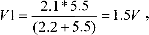

本实施例的耳机设计方案根据电气特征值设定相应门限来检测耳机的正常插入状态以及按键开关SW的按压状态,从而实现了耳机插入识别、音乐播放、对讲通话等功能,完全可以满足目前Qchat对讲手机的各项耳机控制功能。The earphone design scheme of this embodiment sets the corresponding threshold according to the electrical characteristic value to detect the normal insertion state of the earphone and the pressing state of the key switch SW, thereby realizing functions such as earphone insertion identification, music playback, and intercom conversation, which can fully meet the current requirements. Various earphone control functions of Qchat intercom mobile phone.
当然,本实施例所提出的耳机设计方案同样也适用于除手机以外的其它终端产品,本实施例对此不进行具体限制。Of course, the earphone design scheme proposed in this embodiment is also applicable to other terminal products except mobile phones, and this embodiment does not specifically limit it.
应当指出的是,以上所述仅是本实用新型的一种优选实施方式,对于本技术领域的普通技术人员来说,在不脱离本实用新型原理的前提下,还可以做出若干改进和润饰,这些改进和润饰也应视为本实用新型的保护范围。It should be noted that the above description is only a preferred embodiment of the utility model, and those skilled in the art can make some improvements and modifications without departing from the principle of the utility model , These improvements and modifications should also be regarded as the protection scope of the present utility model.
Claims (10)
Priority Applications (1)
| Application Number | Priority Date | Filing Date | Title |
|---|---|---|---|
| CN2011200248901U CN201928419U (en) | 2011-01-21 | 2011-01-21 | Earphone and mobile communication terminal provided with same |
Applications Claiming Priority (1)
| Application Number | Priority Date | Filing Date | Title |
|---|---|---|---|
| CN2011200248901U CN201928419U (en) | 2011-01-21 | 2011-01-21 | Earphone and mobile communication terminal provided with same |
Publications (1)
| Publication Number | Publication Date |
|---|---|
| CN201928419U true CN201928419U (en) | 2011-08-10 |
Family
ID=44432252
Family Applications (1)
| Application Number | Title | Priority Date | Filing Date |
|---|---|---|---|
| CN2011200248901U Expired - Fee Related CN201928419U (en) | 2011-01-21 | 2011-01-21 | Earphone and mobile communication terminal provided with same |
Country Status (1)
| Country | Link |
|---|---|
| CN (1) | CN201928419U (en) |
Cited By (43)
| Publication number | Priority date | Publication date | Assignee | Title |
|---|---|---|---|---|
| CN102448007A (en) * | 2011-12-21 | 2012-05-09 | 上海博泰悦臻电子设备制造有限公司 | Microphone diagnosis circuit |
| CN103167367A (en) * | 2011-12-19 | 2013-06-19 | 腾讯科技(深圳)有限公司 | Earphone and voice message drive-by-wire method and system |
| WO2013123856A1 (en) * | 2012-02-22 | 2013-08-29 | 腾讯科技(深圳)有限公司 | Earphone wire control device, earphone, and voice recording system and method |
| CN103414060A (en) * | 2013-07-22 | 2013-11-27 | 张华� | Earphone socket |
| CN103731560A (en) * | 2014-01-13 | 2014-04-16 | 联想(北京)有限公司 | Electronic device and control method thereof |
| CN104038863A (en) * | 2013-03-04 | 2014-09-10 | 上海城市地理信息系统发展有限公司 | Method and apparatus for simulating earphone button to transmit data |
| CN104519445A (en) * | 2014-12-10 | 2015-04-15 | 天地融科技股份有限公司 | Phonetic code product and phonetic code communication channel circuit |
| CN104780477A (en) * | 2015-03-20 | 2015-07-15 | 福建一丁芯智能技术有限公司 | Earphone insert pin convenient for mobile phone talkback operation |
| CN105187631A (en) * | 2015-07-31 | 2015-12-23 | 是联(北京)科技有限公司 | Intelligent terminal key device based on earphone interface and control method of intelligent terminal key device |
| CN105657598A (en) * | 2016-03-29 | 2016-06-08 | 广东欧珀移动通信有限公司 | Earphone control device suitable for user terminal |
| WO2016101269A1 (en) * | 2014-12-26 | 2016-06-30 | 华为技术有限公司 | Terminal device |
| CN105933810A (en) * | 2016-04-29 | 2016-09-07 | 乐视控股(北京)有限公司 | Earphone mode switching method and apparatus, electronic device, and earphones |
| CN105979438A (en) * | 2016-05-30 | 2016-09-28 | 歌尔股份有限公司 | Wind noise-prevention microphone single body and earphone |
| CN106165214A (en) * | 2014-03-25 | 2016-11-23 | Ifpl集团有限公司 | headphone jack |
| CN106162433A (en) * | 2015-04-10 | 2016-11-23 | 杭州纳雄科技有限公司 | A kind of head circuit and control method thereof |
| CN106231477A (en) * | 2016-09-28 | 2016-12-14 | 青岛海信移动通信技术股份有限公司 | Process method and the terminal of the operation of Qchat earphone |
| CN106817644A (en) * | 2017-02-21 | 2017-06-09 | 上海青橙实业有限公司 | A kind of mobile terminal and head circuit |
| TWI617172B (en) * | 2014-09-02 | 2018-03-01 | 蘋果公司 | Method of operating an electronic device, non-transitory computer readable storage medium, and electronic device |
| US9977579B2 (en) | 2014-09-02 | 2018-05-22 | Apple Inc. | Reduced-size interfaces for managing alerts |
| US9998888B1 (en) | 2015-08-14 | 2018-06-12 | Apple Inc. | Easy location sharing |
| CN108574900A (en) * | 2018-05-30 | 2018-09-25 | 成都零壹众科技有限公司 | Public network intercom passive PTT headset based on ordinary mobile phones |
| CN108924684A (en) * | 2018-06-20 | 2018-11-30 | 北京纽曼凤凰科技有限公司 | A kind of earphone and its application method |
| US10272294B2 (en) | 2016-06-11 | 2019-04-30 | Apple Inc. | Activity and workout updates |
| US10375519B2 (en) | 2011-05-23 | 2019-08-06 | Apple Inc. | Identifying and locating users on a mobile network |
| US10375526B2 (en) | 2013-01-29 | 2019-08-06 | Apple Inc. | Sharing location information among devices |
| US10382378B2 (en) | 2014-05-31 | 2019-08-13 | Apple Inc. | Live location sharing |
| US10409483B2 (en) | 2015-03-07 | 2019-09-10 | Apple Inc. | Activity based thresholds for providing haptic feedback |
| CN110225450A (en) * | 2019-06-04 | 2019-09-10 | 福建泉盛电子有限公司 | A kind of communication means and communication system of intercom and mobile phone |
| US10416844B2 (en) | 2014-05-31 | 2019-09-17 | Apple Inc. | Message user interfaces for capture and transmittal of media and location content |
| US10496259B2 (en) | 2014-08-02 | 2019-12-03 | Apple Inc. | Context-specific user interfaces |
| US10613608B2 (en) | 2014-08-06 | 2020-04-07 | Apple Inc. | Reduced-size user interfaces for battery management |
| US10715380B2 (en) | 2011-05-23 | 2020-07-14 | Apple Inc. | Setting a reminder that is triggered by a target user device |
| US10872318B2 (en) | 2014-06-27 | 2020-12-22 | Apple Inc. | Reduced size user interface |
| US10996917B2 (en) | 2019-05-31 | 2021-05-04 | Apple Inc. | User interfaces for audio media control |
| US11080004B2 (en) | 2019-05-31 | 2021-08-03 | Apple Inc. | Methods and user interfaces for sharing audio |
| US11604571B2 (en) | 2014-07-21 | 2023-03-14 | Apple Inc. | Remote user interface |
| US11620103B2 (en) | 2019-05-31 | 2023-04-04 | Apple Inc. | User interfaces for audio media control |
| US11847378B2 (en) | 2021-06-06 | 2023-12-19 | Apple Inc. | User interfaces for audio routing |
| US11947784B2 (en) | 2016-06-11 | 2024-04-02 | Apple Inc. | User interface for initiating a telephone call |
| US12107985B2 (en) | 2017-05-16 | 2024-10-01 | Apple Inc. | Methods and interfaces for home media control |
| US12112037B2 (en) | 2020-09-25 | 2024-10-08 | Apple Inc. | Methods and interfaces for media control with dynamic feedback |
| US12244755B2 (en) | 2017-05-16 | 2025-03-04 | Apple Inc. | Methods and interfaces for configuring a device in accordance with an audio tone signal |
| US12423052B2 (en) | 2021-06-06 | 2025-09-23 | Apple Inc. | User interfaces for audio routing |
-
2011
- 2011-01-21 CN CN2011200248901U patent/CN201928419U/en not_active Expired - Fee Related
Cited By (99)
| Publication number | Priority date | Publication date | Assignee | Title |
|---|---|---|---|---|
| US10382895B2 (en) | 2011-05-23 | 2019-08-13 | Apple Inc. | Identifying and locating users on a mobile network |
| US10715380B2 (en) | 2011-05-23 | 2020-07-14 | Apple Inc. | Setting a reminder that is triggered by a target user device |
| US10863307B2 (en) | 2011-05-23 | 2020-12-08 | Apple Inc. | Identifying and locating users on a mobile network |
| US11665505B2 (en) | 2011-05-23 | 2023-05-30 | Apple Inc. | Identifying and locating users on a mobile network |
| US11700168B2 (en) | 2011-05-23 | 2023-07-11 | Apple Inc. | Setting a reminder that is triggered by a target user device |
| US10375519B2 (en) | 2011-05-23 | 2019-08-06 | Apple Inc. | Identifying and locating users on a mobile network |
| US12101687B2 (en) | 2011-05-23 | 2024-09-24 | Apple Inc. | Identifying and locating users on a mobile network |
| CN103167367B (en) * | 2011-12-19 | 2015-10-14 | 腾讯科技(深圳)有限公司 | A kind of earphone, voice message drive-by-wire method and system |
| CN103167367A (en) * | 2011-12-19 | 2013-06-19 | 腾讯科技(深圳)有限公司 | Earphone and voice message drive-by-wire method and system |
| CN102448007A (en) * | 2011-12-21 | 2012-05-09 | 上海博泰悦臻电子设备制造有限公司 | Microphone diagnosis circuit |
| WO2013123856A1 (en) * | 2012-02-22 | 2013-08-29 | 腾讯科技(深圳)有限公司 | Earphone wire control device, earphone, and voice recording system and method |
| CN103297885A (en) * | 2012-02-22 | 2013-09-11 | 腾讯科技(深圳)有限公司 | Earphone wire control device, earphone and voice recording system and method |
| US10375526B2 (en) | 2013-01-29 | 2019-08-06 | Apple Inc. | Sharing location information among devices |
| CN104038863A (en) * | 2013-03-04 | 2014-09-10 | 上海城市地理信息系统发展有限公司 | Method and apparatus for simulating earphone button to transmit data |
| CN103414060A (en) * | 2013-07-22 | 2013-11-27 | 张华� | Earphone socket |
| CN103731560A (en) * | 2014-01-13 | 2014-04-16 | 联想(北京)有限公司 | Electronic device and control method thereof |
| CN103731560B (en) * | 2014-01-13 | 2016-07-06 | 联想(北京)有限公司 | A kind of electronic equipment and control method thereof |
| CN106165214A (en) * | 2014-03-25 | 2016-11-23 | Ifpl集团有限公司 | headphone jack |
| US11513661B2 (en) | 2014-05-31 | 2022-11-29 | Apple Inc. | Message user interfaces for capture and transmittal of media and location content |
| US11943191B2 (en) | 2014-05-31 | 2024-03-26 | Apple Inc. | Live location sharing |
| US10732795B2 (en) | 2014-05-31 | 2020-08-04 | Apple Inc. | Message user interfaces for capture and transmittal of media and location content |
| US10592072B2 (en) | 2014-05-31 | 2020-03-17 | Apple Inc. | Message user interfaces for capture and transmittal of media and location content |
| US10564807B2 (en) | 2014-05-31 | 2020-02-18 | Apple Inc. | Message user interfaces for capture and transmittal of media and location content |
| US10416844B2 (en) | 2014-05-31 | 2019-09-17 | Apple Inc. | Message user interfaces for capture and transmittal of media and location content |
| US12395458B2 (en) | 2014-05-31 | 2025-08-19 | Apple Inc. | Live location sharing |
| US10382378B2 (en) | 2014-05-31 | 2019-08-13 | Apple Inc. | Live location sharing |
| US11775145B2 (en) | 2014-05-31 | 2023-10-03 | Apple Inc. | Message user interfaces for capture and transmittal of media and location content |
| US11720861B2 (en) | 2014-06-27 | 2023-08-08 | Apple Inc. | Reduced size user interface |
| US11250385B2 (en) | 2014-06-27 | 2022-02-15 | Apple Inc. | Reduced size user interface |
| US12361388B2 (en) | 2014-06-27 | 2025-07-15 | Apple Inc. | Reduced size user interface |
| US12299642B2 (en) | 2014-06-27 | 2025-05-13 | Apple Inc. | Reduced size user interface |
| US10872318B2 (en) | 2014-06-27 | 2020-12-22 | Apple Inc. | Reduced size user interface |
| US11604571B2 (en) | 2014-07-21 | 2023-03-14 | Apple Inc. | Remote user interface |
| US12093515B2 (en) | 2014-07-21 | 2024-09-17 | Apple Inc. | Remote user interface |
| US11740776B2 (en) | 2014-08-02 | 2023-08-29 | Apple Inc. | Context-specific user interfaces |
| US12430013B2 (en) | 2014-08-02 | 2025-09-30 | Apple Inc. | Context-specific user interfaces |
| US10496259B2 (en) | 2014-08-02 | 2019-12-03 | Apple Inc. | Context-specific user interfaces |
| US11561596B2 (en) | 2014-08-06 | 2023-01-24 | Apple Inc. | Reduced-size user interfaces for battery management |
| US10613608B2 (en) | 2014-08-06 | 2020-04-07 | Apple Inc. | Reduced-size user interfaces for battery management |
| US11256315B2 (en) | 2014-08-06 | 2022-02-22 | Apple Inc. | Reduced-size user interfaces for battery management |
| US10901482B2 (en) | 2014-08-06 | 2021-01-26 | Apple Inc. | Reduced-size user interfaces for battery management |
| TWI617172B (en) * | 2014-09-02 | 2018-03-01 | 蘋果公司 | Method of operating an electronic device, non-transitory computer readable storage medium, and electronic device |
| US11700326B2 (en) | 2014-09-02 | 2023-07-11 | Apple Inc. | Phone user interface |
| US9930157B2 (en) | 2014-09-02 | 2018-03-27 | Apple Inc. | Phone user interface |
| US9977579B2 (en) | 2014-09-02 | 2018-05-22 | Apple Inc. | Reduced-size interfaces for managing alerts |
| US11379071B2 (en) | 2014-09-02 | 2022-07-05 | Apple Inc. | Reduced-size interfaces for managing alerts |
| US10320963B2 (en) | 2014-09-02 | 2019-06-11 | Apple Inc. | Phone user interface |
| US10771606B2 (en) | 2014-09-02 | 2020-09-08 | Apple Inc. | Phone user interface |
| US11989364B2 (en) | 2014-09-02 | 2024-05-21 | Apple Inc. | Reduced-size interfaces for managing alerts |
| US10379714B2 (en) | 2014-09-02 | 2019-08-13 | Apple Inc. | Reduced-size interfaces for managing alerts |
| US10015298B2 (en) | 2014-09-02 | 2018-07-03 | Apple Inc. | Phone user interface |
| CN104519445A (en) * | 2014-12-10 | 2015-04-15 | 天地融科技股份有限公司 | Phonetic code product and phonetic code communication channel circuit |
| CN105934931A (en) * | 2014-12-26 | 2016-09-07 | 华为技术有限公司 | a terminal device |
| WO2016101269A1 (en) * | 2014-12-26 | 2016-06-30 | 华为技术有限公司 | Terminal device |
| CN105934931B (en) * | 2014-12-26 | 2019-07-19 | 华为技术有限公司 | a terminal device |
| US10409483B2 (en) | 2015-03-07 | 2019-09-10 | Apple Inc. | Activity based thresholds for providing haptic feedback |
| CN104780477A (en) * | 2015-03-20 | 2015-07-15 | 福建一丁芯智能技术有限公司 | Earphone insert pin convenient for mobile phone talkback operation |
| CN106162433A (en) * | 2015-04-10 | 2016-11-23 | 杭州纳雄科技有限公司 | A kind of head circuit and control method thereof |
| CN106162433B (en) * | 2015-04-10 | 2021-08-24 | 杭州纳雄科技有限公司 | Earphone circuit and control method thereof |
| CN105187631A (en) * | 2015-07-31 | 2015-12-23 | 是联(北京)科技有限公司 | Intelligent terminal key device based on earphone interface and control method of intelligent terminal key device |
| US11418929B2 (en) | 2015-08-14 | 2022-08-16 | Apple Inc. | Easy location sharing |
| US10341826B2 (en) | 2015-08-14 | 2019-07-02 | Apple Inc. | Easy location sharing |
| US9998888B1 (en) | 2015-08-14 | 2018-06-12 | Apple Inc. | Easy location sharing |
| US10003938B2 (en) | 2015-08-14 | 2018-06-19 | Apple Inc. | Easy location sharing |
| US12089121B2 (en) | 2015-08-14 | 2024-09-10 | Apple Inc. | Easy location sharing |
| CN105657598B (en) * | 2016-03-29 | 2018-03-27 | 广东欧珀移动通信有限公司 | A kind of earphone control device suitable for user terminal |
| CN105657598A (en) * | 2016-03-29 | 2016-06-08 | 广东欧珀移动通信有限公司 | Earphone control device suitable for user terminal |
| CN105933810A (en) * | 2016-04-29 | 2016-09-07 | 乐视控股(北京)有限公司 | Earphone mode switching method and apparatus, electronic device, and earphones |
| CN105979438A (en) * | 2016-05-30 | 2016-09-28 | 歌尔股份有限公司 | Wind noise-prevention microphone single body and earphone |
| US11918857B2 (en) | 2016-06-11 | 2024-03-05 | Apple Inc. | Activity and workout updates |
| US11660503B2 (en) | 2016-06-11 | 2023-05-30 | Apple Inc. | Activity and workout updates |
| US11148007B2 (en) | 2016-06-11 | 2021-10-19 | Apple Inc. | Activity and workout updates |
| US11947784B2 (en) | 2016-06-11 | 2024-04-02 | Apple Inc. | User interface for initiating a telephone call |
| US12274918B2 (en) | 2016-06-11 | 2025-04-15 | Apple Inc. | Activity and workout updates |
| US10272294B2 (en) | 2016-06-11 | 2019-04-30 | Apple Inc. | Activity and workout updates |
| US11161010B2 (en) | 2016-06-11 | 2021-11-02 | Apple Inc. | Activity and workout updates |
| CN106231477A (en) * | 2016-09-28 | 2016-12-14 | 青岛海信移动通信技术股份有限公司 | Process method and the terminal of the operation of Qchat earphone |
| CN106817644A (en) * | 2017-02-21 | 2017-06-09 | 上海青橙实业有限公司 | A kind of mobile terminal and head circuit |
| US12244755B2 (en) | 2017-05-16 | 2025-03-04 | Apple Inc. | Methods and interfaces for configuring a device in accordance with an audio tone signal |
| US12526361B2 (en) | 2017-05-16 | 2026-01-13 | Apple Inc. | Methods for outputting an audio output in accordance with a user being within a range of a device |
| US12107985B2 (en) | 2017-05-16 | 2024-10-01 | Apple Inc. | Methods and interfaces for home media control |
| CN108574900B (en) * | 2018-05-30 | 2024-01-30 | 成都零壹众科技有限公司 | Public network intercom passive PTT earphone based on common mobile phone |
| CN108574900A (en) * | 2018-05-30 | 2018-09-25 | 成都零壹众科技有限公司 | Public network intercom passive PTT headset based on ordinary mobile phones |
| CN108924684A (en) * | 2018-06-20 | 2018-11-30 | 北京纽曼凤凰科技有限公司 | A kind of earphone and its application method |
| US11010121B2 (en) | 2019-05-31 | 2021-05-18 | Apple Inc. | User interfaces for audio media control |
| US11620103B2 (en) | 2019-05-31 | 2023-04-04 | Apple Inc. | User interfaces for audio media control |
| US11853646B2 (en) | 2019-05-31 | 2023-12-26 | Apple Inc. | User interfaces for audio media control |
| US12504944B2 (en) | 2019-05-31 | 2025-12-23 | Apple Inc. | Methods and user interfaces for sharing audio |
| US11157234B2 (en) | 2019-05-31 | 2021-10-26 | Apple Inc. | Methods and user interfaces for sharing audio |
| US12223228B2 (en) | 2019-05-31 | 2025-02-11 | Apple Inc. | User interfaces for audio media control |
| US11755273B2 (en) | 2019-05-31 | 2023-09-12 | Apple Inc. | User interfaces for audio media control |
| US10996917B2 (en) | 2019-05-31 | 2021-05-04 | Apple Inc. | User interfaces for audio media control |
| US11714597B2 (en) | 2019-05-31 | 2023-08-01 | Apple Inc. | Methods and user interfaces for sharing audio |
| US11080004B2 (en) | 2019-05-31 | 2021-08-03 | Apple Inc. | Methods and user interfaces for sharing audio |
| CN110225450A (en) * | 2019-06-04 | 2019-09-10 | 福建泉盛电子有限公司 | A kind of communication means and communication system of intercom and mobile phone |
| CN110225450B (en) * | 2019-06-04 | 2022-09-27 | 福建泉盛电子有限公司 | Communication method and communication system for interphone and mobile phone |
| US12112037B2 (en) | 2020-09-25 | 2024-10-08 | Apple Inc. | Methods and interfaces for media control with dynamic feedback |
| US12423052B2 (en) | 2021-06-06 | 2025-09-23 | Apple Inc. | User interfaces for audio routing |
| US11847378B2 (en) | 2021-06-06 | 2023-12-19 | Apple Inc. | User interfaces for audio routing |
Similar Documents
| Publication | Publication Date | Title |
|---|---|---|
| CN201928419U (en) | Earphone and mobile communication terminal provided with same | |
| CN102404665B (en) | Earphone interface self-adaptation circuit | |
| CN103118191B (en) | Using control method and mobile terminal for iPhone wire control earphone | |
| CN201360281Y (en) | Four-wire interface multimedia wire control earphone and terminal supporting same | |
| CN101924835B (en) | Mobile telephone communication method and mobile telephone | |
| CN202602769U (en) | Conversation type electronic product with echo inhibition function | |
| CN102143262A (en) | Electronic device and method for switching audio input channel thereof | |
| CN101938546A (en) | Earphone microphone detection method based on mobile phone and mobile phone | |
| CN107770663B (en) | In-ear wireless earphone and realization method for automatic charging and switching on/off of in-ear wireless earphone | |
| CN107770662B (en) | Automatic charging and switching circuit | |
| CN102035911A (en) | Device and method for accessing earphone of mobile phone | |
| CN206077633U (en) | A kind of In-Ear wireless headset | |
| CN104254040B (en) | Mobile communication terminal Audio conversion system | |
| CN202750144U (en) | Walkie-talkie mobile phone | |
| CN102395072B (en) | A kind of headset plug and earphone thereof | |
| CN102710821B (en) | Hand microphone for interphone and interphone | |
| CN102256202B (en) | Mobile terminal and method for realizing compatibility of hearing aid by same | |
| CN101945172A (en) | Mobile phone-based earphone recognition calling method and mobile phone | |
| CN201781517U (en) | Mobile phone device | |
| CN207166701U (en) | A kind of head circuit | |
| WO2018018738A1 (en) | Multifunctional loudspeaker | |
| CN202713580U (en) | Earphone compatible interface circuit for terminal device | |
| CN216017133U (en) | Bluetooth headset charging box and earphone system | |
| CN201479354U (en) | Power amplifier muting circuit | |
| CN206865523U (en) | Mobile phone with bone-conduction speaker |
Legal Events
| Date | Code | Title | Description |
|---|---|---|---|
| C14 | Grant of patent or utility model | ||
| GR01 | Patent grant | ||
| C17 | Cessation of patent right | ||
| CF01 | Termination of patent right due to non-payment of annual fee |
Granted publication date: 20110810 Termination date: 20140121 |