CN201722124U - Full-automatic sauce filling machine - Google Patents
Full-automatic sauce filling machine Download PDFInfo
- Publication number
- CN201722124U CN201722124U CN2010202232937U CN201020223293U CN201722124U CN 201722124 U CN201722124 U CN 201722124U CN 2010202232937 U CN2010202232937 U CN 2010202232937U CN 201020223293 U CN201020223293 U CN 201020223293U CN 201722124 U CN201722124 U CN 201722124U
- Authority
- CN
- China
- Prior art keywords
- automatic control
- control device
- fill head
- filling
- full automaticity
- Prior art date
- Legal status (The legal status is an assumption and is not a legal conclusion. Google has not performed a legal analysis and makes no representation as to the accuracy of the status listed.)
- Expired - Lifetime
Links
Images


Landscapes
- Basic Packing Technique (AREA)
Abstract
The utility model discloses a full-automatic sauce filling machine, which comprises a machine case, a storage bucket and a filling mechanism, wherein the storage bucket is arranged in the machine case; the filling mechanism comprises at least a filling head; the filling head is communicated with the storage bucket through a combination valve body, and is arranged on a filling head bracket; the filling head bracket is connected with a filling head driving device arranged on the machine case; an electric cabinet is arranged on the machine case; an automatic control device is arranged in the electric cabinet; a conveying device is arranged below the filling head; and control components of the combination valve body, the filling head driving device and the conveying device are electrically connected with the automatic control device. The utility model utilizes a set of full-automatic filling system to realize the filling operation with uniform filling quantity and accurate metering through the control of the automatic control device, can adapt to bottle apparatus with different calibers, and meet the filling requirements of bottles with different shapes; and the filling quantity can be adjusted, and the filling efficiency is high.
Description
Technical field
The utility model relates to technical fields such as a kind of food, medicine, particularly a kind of automatic filling machine that is applicable to can sauce class material.
Background technology
Industries such as food, medicine often need be carried out can to sauce class material at present, often adopted manual method to come can in the past, the easy like this can amount that causes is inhomogeneous, sanitary condition can not get guaranteeing, and the inefficiency of whole can, labour intensity is big, and the human cost height can't be realized automatization level and effect fully.
The utility model content
Goal of the invention of the present utility model is, at the problem of above-mentioned existence, provides a kind of can efficient height, and the can amount is even, can adapt to the doleiform utensil of different bores, the can demand of difformity doleiform, the full automaticity sauce class bottle placer of can amount adjustable size.
The technical solution of the utility model is achieved in that a kind of full automaticity sauce class bottle placer, comprise cabinet, storage vat and filling mechanism, described storage vat is arranged in the cabinet, it is characterized in that: described filling mechanism comprises at least one fill head, described fill head is communicated with storage vat by combinaing valve body, described fill head is arranged on the fill head support, described fill head support is connected with fill head actuating device on being arranged on cabinet, described cabinet is provided with electric cabinet, in described electric cabinet, be provided with automatic control device, below described fill head, be provided with feedway, described combinaing valve body, the function unit of fill head actuating device and feedway is electrically connected with automatic control device.
Full automaticity sauce class bottle placer described in the utility model, its described combinaing valve body comprises multi-channel change-over valve and measuring pump, described multi-channel change-over valve comprises valve body and spool, described spool is arranged in the valve body, described valve body is provided with at least one group of switching channel that is interconnected by at least three communication ports, described spool is provided with and the cooresponding separate cavity of switching channel, described cavity be provided with every group of switching channel on the corresponding through hole of communication port, described spool is connected with rotating driving device, described measuring pump is communicated with a communication port in the switching channel, described fill head and the corresponding connection of another communication port in the switching channel, the function unit of described measuring pump and rotating driving device is electrically connected with automatic control device.
Full automaticity sauce class bottle placer described in the utility model, its described measuring pump comprises metering cylinder and connecting rod, described metering cylinder is communicated with a communication port in the switching channel, one end of described connecting rod is connected with the piston of setting in the metering cylinder, its other end is connected with retractable driving device by draw-bar seat, and the function unit of described retractable driving device is electrically connected with automatic control device.
Full automaticity sauce class bottle placer described in the utility model, its described fill head actuating device is connected with apparatus for adjusting position.
Full automaticity sauce class bottle placer described in the utility model, its described filling mechanism forms the can zone on its cooresponding feedway, input end and mouth in described can zone are respectively arranged with photoelectric sensor, and described photoelectric sensor is electrically connected with automatic control device.
Full automaticity sauce class bottle placer described in the utility model, its described cabinet is provided with inhibiting device, and described inhibiting device is arranged at the input end and the mouth in described can zone respectively.
Full automaticity sauce class bottle placer described in the utility model, its described inhibiting device comprises spacing cylinder and pin, and described pin is connected with spacing air cylinder driven, and the function unit of described spacing cylinder is electrically connected with automatic control device.
Full automaticity sauce class bottle placer described in the utility model, it is provided with puddler in described storage vat, and described puddler is connected with the stirring drive motor.
Full automaticity sauce class bottle placer described in the utility model, its described feedway is provided with anti-down bottle, and described anti-down bottle comprises retaining bottle adjusting bracket, and described shelves bottle adjusting bracket is provided with at least one horizon bar.
Full automaticity sauce class bottle placer described in the utility model, its described feedway comprises belt conveyor and reducing motor, and described belt conveyor is driven by reducing motor, and the function unit of described reducing motor is electrically connected with automatic control device.
The utility model utilizes the full automatic bulking system of a cover, can realize the operation of can by the control of automatic control device, and the can amount is even, metering accurately can adapt to the doleiform utensil of different bores, the can demand of difformity doleiform, can amount adjustable size, can efficient is very high.Adopt this full automaticity sauce class bottle placer, efficiently solve the problems that artificial fill operations mode exists, significantly reduced the expenditure of waste of manpower resource and cost.
Description of drawings
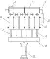
Fig. 1 is a structural representation of the present utility model.
Fig. 2 is the structural representation of the utility model cabinet inside.
Fig. 3 is the structural representation of the utility model combinaing valve body.
Fig. 4 is the structural representation of spool in the utility model combinaing valve body.
Fig. 5 is the structural representation of a kind of state of multi-channel transfer valve in the utility model combinaing valve body.
Fig. 6 is the structural representation of the another kind of state of multi-channel transfer valve in the utility model combinaing valve body.
Mark among the figure: 1 is cabinet, and 2 is storage vat, and 3 is fill head, 4 is combinaing valve body, and 5 is the fill head support, and 6 is electric cabinet, 7 is valve body, and 8 is spool, and 9 is switching channel, 10 is cavity, 11,11a, 11b, 11c is a through hole, and 12 is metering cylinder, 13 is connecting rod, and 14 is draw-bar seat, and 15 is apparatus for adjusting position, 16 are the can zone, and 17 is photoelectric sensor, and 18 is pin, 19 is puddler, and 20 for stirring drive motor, 21 grades of bottle adjusting brackets, 22 is horizon bar, and 23 is belt conveyor, and 24 is reducing motor, 25 is discharge nozzle, 26a, 26b, 26c is a communication port, and 27 is cylinder A, 28 is cylinder B, and 29 is cylinder C.
The specific embodiment
Below in conjunction with accompanying drawing, the utility model is done detailed explanation.
In order to make the purpose of this utility model, technical scheme and advantage clearer,, the utility model is further elaborated below in conjunction with drawings and Examples.Should be appreciated that specific embodiment described herein only in order to explanation the utility model, and be not used in qualification the utility model.
As illustrated in fig. 1 and 2, full automaticity sauce class bottle placer, comprise cabinet 1, storage vat 2 and filling mechanism, described storage vat 2 is arranged in the cabinet 1, and described filling mechanism comprises six fill head 3, and described fill head 3 is communicated with storage vat 2 by combinaing valve body 4, described fill head 3 is arranged on the fill head support 5, described fill head support 5 is connected with fill head actuating device on being arranged on cabinet 1, and described fill head actuating device is cylinder C29, and described cylinder C is connected with apparatus for adjusting position 15.
Described cabinet 1 is provided with electric cabinet 6, in described electric cabinet 6, be provided with automatic control device, be provided with feedway below described fill head 3, described feedway comprises belt conveyor 23 and reducing motor 24, and described belt conveyor 23 is driven by reducing motor 24.
Described filling mechanism forms can zone 16 on its cooresponding feedway, input end and mouth in described can zone 16 are respectively arranged with photoelectric sensor 17, and described photoelectric sensor 17 is regulated support by photoelectric sensor and is connected with cabinet 1; Described feedway is provided with inhibiting device, and described inhibiting device is arranged at the input end and the mouth in described can zone 16 respectively, and described inhibiting device comprises spacing cylinder and pin 18, and described pin 18 is connected with spacing air cylinder driven; On described feedway, also be provided with anti-down bottle, described anti-down bottle comprises shelves bottle adjusting bracket 21, described shelves bottle adjusting bracket 21 is provided with two horizon bars 22, and described horizon bar can guarantee that the operation of bottle is smooth and easy according to bottle type different adjustment height and width.
Wherein, be provided with puddler 19 in described storage vat 2, described puddler 19 is connected with stirring drive motor 20.
As shown in Figure 3, described combinaing valve body comprises multi-channel change-over valve and six measuring pumps, described multi-channel change-over valve comprises valve body 7 and spool 8, described spool 8 is arranged in the valve body 7, described valve body 7 is provided with six groups by three communication port 26a, 26b, the switching channel 9 that 26c is interconnected, as shown in Figure 4, described spool 8 is provided with and switching channel 9 cooresponding separate cavitys 10, described cavity 10 be provided with every group of switching channel 9 on communication port 26a, 26b, the corresponding through hole 11a of 26c, 11b, 11c, described spool 8 is connected with rotating driving device, described rotating driving device is cylinder A27, described six measuring pumps are communicated with communication port 26a in six groups of switching channels 9 respectively, described communication port 26b is communicated with storage vat 2, and described communication port 26c is communicated with six fill head 3 by discharge nozzle 25 respectively.
Described measuring pump comprises metering cylinder 12 and connecting rod 13, described metering cylinder 12 is communicated with communication port 26a in the switching channel 9, the upper end of described connecting rod 13 is connected with the piston of setting in the metering cylinder 12, and its lower end is connected with retractable driving device by draw-bar seat 14, and described retractable driving device is cylinder B28.
The function unit of wherein said photoelectric sensor 17, spacing cylinder, stirring drive motor 20, reducing motor 24, cylinder A27, cylinder B28 and cylinder C29 is electrically connected with automatic control device respectively.
Principle of work of the present utility model: doleiform utensil to be filled is put on the belt conveyor of feedway, start reducing motor by automatic control device, thereby drive the belt conveyor running, when first bottle is sent to can zone input end, the photoelectric sensor that is arranged at can zone input end receives a bottle signal that enters the can zone and begins counting, after quantity reaches six, photoelectric sensor sends signal to automatic control device, after automatic control device is received signal, the control reducing motor decommissions, simultaneously, automatic control device is controlled the action of spacing cylinder, and the pin that spacing air cylinder driven is attached thereto stretches out, and blocks further that the extra-regional bottle of can enters in the can zone on the belt conveyor, wait to enter six bottles in the can zone fully static after, under the control of automatic control device, begin to carry out the can operation.
As shown in Figure 5, this moment combinaing valve body the multi-channel change-over valve on the spool through hole 11a, 11b respectively with the corresponding connection of communication port 26a, 26b of valve body, thereby communication port 26a, 26b on the valve body are interconnected, at first automatic control device control cylinder B action, the piston that drives in the metering cylinder by the draw-bar seat drive link moves down, material in the storage vat is extracted in the metering cylinder, utilize metering cylinder that material is carried out accurate quantification, after reaching aequum, automatic control device control cylinder B stops action.
Then, automatic control device control cylinder A action, make spool conter clockwise half-twist under the driving of cylinder A, as shown in Figure 6, this moment through hole 11c, the 11a on the spool respectively with the corresponding connection of communication port 26a, 26c of valve body, thereby communication port 26a, 26c on the valve body are interconnected, and automatic control device control cylinder C action simultaneously extend into six fill head in the cooresponding with it bottle in its below by the fill head support; At last, cylinder B is action once more under the control of automatic control device, the piston that drives in the metering cylinder by the draw-bar seat drive link moves up, like this, material in six metering cylinders then extrudes from cooresponding six fill head by discharge nozzle simultaneously, after having pressed, and automatic control device control cylinder C action, fill head is shifted out from bottle, thereby finish can action can zone bottle.
After can finishes, automatic control device is controlled spacing cylinder action, pin is withdrawn, automatic control device is controlled the reducing motor running more then, belt conveyor turns round once more, bottle ahead running under the drive of belt conveyor of finishing of can in this moment can zone, the photoelectric sensor that is arranged at can zone mouth is counted it, and the photoelectric sensor of can zone input end is also being counted the bottle to be filled that newly enters simultaneously, after if the counting of two photoelectric sensors is six, automatic control device is controlled reducing motor once more and is shut down, and repeats top can action then; If the counting difference of two photoelectric sensors (counting of a photoelectric sensor reaches six, and another photoelectric sensor must count do not reach six), then automatic control device stops all actions and sends voice prompt, schematic operation person checks.
In storage vat, be provided with puddler, described puddler is connected with the stirring drive motor, described stirring drive motor starts under the control of automatic control device, guarantee in can, material in the storage vat can not make material remain uniform state because of deposited phenomenon appears in long storage time.
Wherein said fill head is regulated support by apparatus for adjusting position and photoelectric sensor respectively with photoelectric sensor and is connected with cabinet, adjustment by to apparatus for adjusting position and photoelectric sensor adjusting support can adapt to the doleiform utensil of different bores and the demand of difformity doleiform can.
The above only is preferred embodiment of the present utility model; not in order to restriction the utility model; all any modifications of within spirit of the present utility model and principle, being done, be equal to and replace and improvement etc., all should be included within the protection domain of the present utility model.
Claims (10)
1. full automaticity sauce class bottle placer, comprise cabinet (1), storage vat (2) and filling mechanism, described storage vat (2) is arranged in the cabinet (1), it is characterized in that: described filling mechanism comprises at least one fill head (3), described fill head (3) is communicated with storage vat (2) by combinaing valve body (4), described fill head (3) is arranged on the fill head support (5), described fill head support (5) is connected with fill head actuating device on being arranged on cabinet (1), described cabinet (1) is provided with electric cabinet (6), in described electric cabinet (6), be provided with automatic control device, be provided with feedway, described combinaing valve body (4) in described fill head (3) below, the function unit of fill head actuating device and feedway is electrically connected with automatic control device.
2. full automaticity sauce class bottle placer according to claim 1, it is characterized in that: described combinaing valve body comprises multi-channel change-over valve and measuring pump, described multi-channel change-over valve comprises valve body (7) and spool (8), described spool (8) is arranged in the valve body (7), described valve body (7) is provided with at least one group of switching channel that is interconnected by at least three communication ports (9), described spool (8) is provided with and the cooresponding separate cavity of switching channel (9) (10), described cavity (10) is provided with every group of switching channel (9) and goes up the corresponding through hole of communication port (11), described spool (8) is connected with rotating driving device, described measuring pump is communicated with a communication port in the switching channel (9), the corresponding connection of another communication port in described fill head (3) and the switching channel (9), the function unit of described measuring pump and rotating driving device is electrically connected with automatic control device.
3. full automaticity sauce class bottle placer according to claim 2, it is characterized in that: described measuring pump comprises metering cylinder (12) and connecting rod (13), described metering cylinder (12) is communicated with a communication port in the switching channel (9), one end of described connecting rod (13) is connected with the piston of setting in the metering cylinder (12), its other end is connected with retractable driving device by draw-bar seat (14), and the function unit of described retractable driving device is electrically connected with automatic control device.
4. according to claim 1 or 2 or 3 described full automaticity sauce class bottle placers, it is characterized in that: described fill head actuating device is connected with apparatus for adjusting position (15).
5. full automaticity sauce class bottle placer according to claim 4, it is characterized in that: described filling mechanism forms can zone (16) on its cooresponding feedway, input end and mouth in described can zone (16) are respectively arranged with photoelectric sensor (17), and described photoelectric sensor (17) is electrically connected with automatic control device.
6. full automaticity sauce class bottle placer according to claim 5, it is characterized in that: described cabinet (1) is provided with inhibiting device, and described inhibiting device is arranged at the input end and the mouth in described can zone (16) respectively.
7. full automaticity sauce class bottle placer according to claim 6, it is characterized in that: described inhibiting device comprises spacing cylinder and pin (18), described pin (18) is connected with spacing air cylinder driven, and the function unit of described spacing cylinder is electrically connected with automatic control device.
8. full automaticity sauce class bottle placer according to claim 7 is characterized in that: be provided with puddler (19) in described storage vat (2), described puddler (19) is connected with stirring drive motor (20).
9. full automaticity sauce class bottle placer according to claim 8, it is characterized in that: described feedway is provided with anti-down bottle, described anti-down bottle comprises retaining bottle adjusting bracket (21), and described retaining bottle adjusting bracket (21) is provided with at least one horizon bar (22).
10. full automaticity sauce class bottle placer according to claim 1, it is characterized in that: described feedway comprises belt conveyor (23) and reducing motor (24), described belt conveyor (23) is driven by reducing motor (24), and the function unit of described reducing motor (24) is electrically connected with automatic control device.
Priority Applications (1)
| Application Number | Priority Date | Filing Date | Title |
|---|---|---|---|
| CN2010202232937U CN201722124U (en) | 2010-06-11 | 2010-06-11 | Full-automatic sauce filling machine |
Applications Claiming Priority (1)
| Application Number | Priority Date | Filing Date | Title |
|---|---|---|---|
| CN2010202232937U CN201722124U (en) | 2010-06-11 | 2010-06-11 | Full-automatic sauce filling machine |
Publications (1)
| Publication Number | Publication Date |
|---|---|
| CN201722124U true CN201722124U (en) | 2011-01-26 |
Family
ID=43490434
Family Applications (1)
| Application Number | Title | Priority Date | Filing Date |
|---|---|---|---|
| CN2010202232937U Expired - Lifetime CN201722124U (en) | 2010-06-11 | 2010-06-11 | Full-automatic sauce filling machine |
Country Status (1)
| Country | Link |
|---|---|
| CN (1) | CN201722124U (en) |
Cited By (12)
| Publication number | Priority date | Publication date | Assignee | Title |
|---|---|---|---|---|
| CN103213925A (en) * | 2013-03-04 | 2013-07-24 | 张朝群 | Automatic filling machine |
| CN103241695A (en) * | 2013-05-17 | 2013-08-14 | 成都中牧生物药业有限公司 | Automated liquid medicine filling device |
| CN103771323A (en) * | 2012-10-23 | 2014-05-07 | 江苏柯本机电工具有限公司 | Jam filling and sealing machine |
| CN104003340A (en) * | 2013-09-12 | 2014-08-27 | 温州市沪华机械电器有限公司 | Pigment loading system |
| CN106966349A (en) * | 2016-01-14 | 2017-07-21 | 内蒙古蒙牛乳业(集团)股份有限公司 | packaging device |
| CN107487470A (en) * | 2017-06-30 | 2017-12-19 | 中山诺顿科研技术服务有限公司 | Sauce material liquid filling machine |
| CN108046194A (en) * | 2017-12-22 | 2018-05-18 | 东阿阿胶股份有限公司 | A kind of servo bottle placer for sticky material |
| CN108284972A (en) * | 2018-01-23 | 2018-07-17 | 青岛博瑞设备制造有限公司 | Egg flower soup bottle placer |
| CN108313395A (en) * | 2018-02-05 | 2018-07-24 | 北京东方卓成科技有限公司 | Multistation bowl falling machine |
| CN108439306A (en) * | 2018-05-07 | 2018-08-24 | 李雨泽 | A kind of automatic filling machine |
| CN109334274A (en) * | 2018-11-22 | 2019-02-15 | 上海精智实业股份有限公司 | A kind of automatic identification and marking equipment |
| CN115259059A (en) * | 2022-08-27 | 2022-11-01 | 河北利华药业有限公司 | Injection liquid filling machine |
-
2010
- 2010-06-11 CN CN2010202232937U patent/CN201722124U/en not_active Expired - Lifetime
Cited By (14)
| Publication number | Priority date | Publication date | Assignee | Title |
|---|---|---|---|---|
| CN103771323A (en) * | 2012-10-23 | 2014-05-07 | 江苏柯本机电工具有限公司 | Jam filling and sealing machine |
| CN103213925A (en) * | 2013-03-04 | 2013-07-24 | 张朝群 | Automatic filling machine |
| CN103213925B (en) * | 2013-03-04 | 2015-08-19 | 广州市美驰化妆品有限公司 | A kind of automatic filling machine |
| CN103241695A (en) * | 2013-05-17 | 2013-08-14 | 成都中牧生物药业有限公司 | Automated liquid medicine filling device |
| CN104003340A (en) * | 2013-09-12 | 2014-08-27 | 温州市沪华机械电器有限公司 | Pigment loading system |
| CN104003340B (en) * | 2013-09-12 | 2016-01-27 | 温州市沪华机械电器有限公司 | Pigment bulking system |
| CN106966349A (en) * | 2016-01-14 | 2017-07-21 | 内蒙古蒙牛乳业(集团)股份有限公司 | packaging device |
| CN107487470A (en) * | 2017-06-30 | 2017-12-19 | 中山诺顿科研技术服务有限公司 | Sauce material liquid filling machine |
| CN108046194A (en) * | 2017-12-22 | 2018-05-18 | 东阿阿胶股份有限公司 | A kind of servo bottle placer for sticky material |
| CN108284972A (en) * | 2018-01-23 | 2018-07-17 | 青岛博瑞设备制造有限公司 | Egg flower soup bottle placer |
| CN108313395A (en) * | 2018-02-05 | 2018-07-24 | 北京东方卓成科技有限公司 | Multistation bowl falling machine |
| CN108439306A (en) * | 2018-05-07 | 2018-08-24 | 李雨泽 | A kind of automatic filling machine |
| CN109334274A (en) * | 2018-11-22 | 2019-02-15 | 上海精智实业股份有限公司 | A kind of automatic identification and marking equipment |
| CN115259059A (en) * | 2022-08-27 | 2022-11-01 | 河北利华药业有限公司 | Injection liquid filling machine |
Similar Documents
| Publication | Publication Date | Title |
|---|---|---|
| CN201722124U (en) | Full-automatic sauce filling machine | |
| CN201722125U (en) | Full-automatic fluid infusion unit | |
| CN105173135B (en) | A kind of accurate automatic filling machine of thick chilli sauce | |
| CN207374718U (en) | A kind of sauce bottle placer | |
| CN101343027B (en) | Weighing type bulking system | |
| CN204297142U (en) | Automatic quantitative tea wrapping machine | |
| CN204606901U (en) | Conical flask loop buffer feedway | |
| CN108713726A (en) | With pot machine | |
| CN108557741A (en) | A kind of intelligence filling liquid production line | |
| CN202670147U (en) | Feeding mechanism of multiple row strip-shaped packing machine | |
| CN204689616U (en) | Bull linear filling machine | |
| CN103342330A (en) | System and method for automatically and quantitatively extracting concentrated juice | |
| CN202226092U (en) | Filling machine | |
| CN205060049U (en) | Accurate automatic filling machine of chilli sauce | |
| KR200451862Y1 (en) | Content multi-injection device with container detection means | |
| CN207536160U (en) | A kind of Lubricating oil filling machine | |
| CN201592980U (en) | Screw pump filling device driven by servo motor | |
| CN207957722U (en) | A kind of filling apparatus of full-automatic chemical reagent bottle placer | |
| CN207827834U (en) | A kind of thick liquid bottle placer | |
| CN219728603U (en) | Soup base filling machine | |
| CN207375727U (en) | A kind of dioxygen milk automatic filling device | |
| CN205603194U (en) | Efficient filling machine | |
| CN203048556U (en) | Airless automatic butter bomb filling machine | |
| CN208470153U (en) | A kind of double-colored material screw filler system | |
| CN210503497U (en) | Water based paint filling device |
Legal Events
| Date | Code | Title | Description |
|---|---|---|---|
| C14 | Grant of patent or utility model | ||
| GR01 | Patent grant | ||
| CX01 | Expiry of patent term |
Granted publication date: 20110126 |
|
| CX01 | Expiry of patent term |